|
Анализатор гематологический Abacus Junior 30 и 30 ND |
||||||
|
||||||
|
||||||
|
||||||
|
||||||
|
||||||
|
||||||
|
||||||
|
||||||
|
||||||
|
||||||
|
||||||
|
||||||
|
||||||
|
||||||
|
||||||
|
||||||
|
||||||
|
||||||
|
||||||
|
||||||
|
||||||
|
||||||
|
||||||
|
||||||
|
||||||
|
||||||
|
||||||
|
||||||
|
||||||
|
||||||
|
||||||
|
||||||
|
||||||
|
||||||
|
||||||
|
||||||
|
||||||
|
||||||
|
||||||
|


5.2.3. Results
The result screen of
5.2.4. Warning flags
Analyzer SW displays warning flags for each individual measurement to notify user
about status of results. The following table summarizes warning flags and gives
explanation of their possible cause and a few hints to overcome the problem.
Flag
Meaning
E
No WBC 3-part
differential
H
HGB blank is high, or no
HGB blank
B
WBC blank is high, or no
WBC blank
M
linearity range exceeded
in WBC stage
R
RBC cells found in
sample during WBC
stage
W
WBC 3-part warning
*
Only in Abacus Junior 30
ROUTINE UTILIZATION & MEASUREMENT
N
D
N
A
b
a
c
u
s
J
u
n
i
o
r
3
0
A
b
a
c
u
s
J
u
n
i
o
r
3
0
Possible lyse problem. May occur in pathological lymphocytosis.
Repeat the blank measurement. If HGB blank is not stable there are
probably bubbles in the WBC chamber: Run a cleaning and try blank
again. Close the side door if open during measurement.
Repeat the blank measurement, or run prime lyse and try blank again.
Possible lyse contamination, or noise problem.
The analyzer found that the cell count is higher than the linearity range of
the analyzer. Make a pre-dilution, and run the same sample in prediluted
mode
RBC cells were detected during the WBC measurement. Either the lyse
reagent is not effective enough (volume should be increased) or the
RBC‟s in the sample are somewhat lyse resistive
*
Probably large PLTs or clumped PLTs are present in the sample. Usually
caused by the nature of the sample. cat and goat samples tend to clump.
Intensive, but careful mixing of the sample (e.g. Vortex) can help remove
the clumps. If the rerun sample gives the same results, consider that
WBC and NEU values seem higher because of the clumps. Lyse
When
analysis
following screen is displayed, including
all measured and calculated parameters
as well as the WBC, RBC, and PLT
histograms.
Results, histograms and other data will
be stored automatically in the memory.
To look at histograms in detail, tap the
arrows (left/right) to see further details.
D
doesn‟t contain the 3-part diff results.
Recommended user action
34
is
complete,
the
-
Contents
-
Table of Contents
-
Troubleshooting
-
Bookmarks
Quick Links
Revision history
Rev.
Date
Edited by
1.0
2009-06-02
Arpad Gyetvai
1.1
2010-03-25
Gabor Farkas
1.11
2011-05-06
Csaba Magyar
Issued
Checked and approved
OM-ACS30-01-1110
Sections affected
Initial revision
First review, new GUI screenshots
1.8
Epson dot-matrix printer support (specifications)
1.8
no 3diff below WBC = 1.00
6.1 (end)
PLT histograms added to result screens
7.4.2.
fast/full self test mode added (MODE button)
8.1
Printout margin settings; Diagnostic flag option
8,2
Data export options selectable
9.1
Printout font changed
Date
Name
06-MAY-2011
Csaba Magyar
Gábor Farkas
17-MAY-2011
Approved by
Csaba Magyar
Csaba Magyar
Gábor Farkas
Signature
Summary of Contents for Diatron Abacus junior 30
Specifications:
|
Accompanying Data:
Diatron Abacus junior 30 Laboratory Equipment PDF Operation & User’s Manual (Updated: Saturday 5th of November 2022 05:09:09 PM)
Rating: 4.7 (rated by 40 users)
Compatible devices: TZT2BB, HV Series, UniCel DxC 600, GA-6, INSTY-PAC Series, Abacus Junior Vet, Tacta, Levelflex M FMP45.
Recommended Documentation:
Text Version of Diatron Abacus junior 30 Operation & User’s Manual
(Ocr-Read Summary of Contents, UPD: 05 November 2022)
-
30, Diatron Abacus junior 30 OPERATING PRINCIPLES 27 4.4. Absolute and Linearity Ranges of Parameters The analyzer provides specified accuracy within its linearity range. Beyond this linearity range, the instrument can display results but accuracy is impaired. If a value is over the maximum r…
-
61, Error! Use the Home tab to apply Címsor 1 to the text that you want to appear here. 58 Users can be added (Add New User) or edited (Edit / View User). Adding a user allows filling in the below parameters. Password must be defined on “Advanced Info” tab. Monogram will be dis…
-
60, Diatron Abacus junior 30 Error! Use the Home tab to apply Címsor 1 to the text that you want to appear here. 57 Settings Date and time Choose the desired time and date format. The analyzer has a built-in battery responsible for running the built-in clock when the unit is powered off. If the analyzer asks for date and ti…
-
14, INTRODUCTION 11 1.5.1. Control Panels START button Pressing and releasing the START button triggers an analysis cycle. Status indicator A two-color (red/green) LED (light emitting diode) is located above START button. Its actual color indicates the status of the analyzer. LED color Analyzer statu…
-
6, TABLE OF CONTENTS 3 8.3. Measurement settings ………………………………………………………………………………….. 54 8.3.1. Unit settings ……………………………………………………………………………….…
-
42, DATABASE 39 6.1. Database services Detail will open up the parameter and histogram view of a record. DATABASE Detail Table returns to the table view. Print sends the record to the printer. Edit opens up the dialog for data manipulation of the record Exit r…
-
64, Error! Use the Home tab to apply Címsor 1 to the text that you want to appear here. 61 QC graphical printout on built-in printer QC graphical printout on external printer
… -
33, ROUTINE UTILIZATION & MEASUREMENT 30 Adapter for 2 ml control blood Figure 10. Vial used in control adapter 1. Remove the cap!! It is very important because the tip can not pierce the cap! 2. Position the sample tube in the sample rotor. 3. …
-
12, INTRODUCTION 9 To replace paper in the printer: — open the paper lid (pull the lid upwards by the handle) — remove central plastic roller of old paper roll — unwind new paper roll, so that the “starting edge” is coming from down under towards you — gently drop the new roll into the h…
-
45, Diatron Abacus junior 30 DATABASE 42 Export: will save selected record(s) to an external USB memory device in the format selected in Export settings (see 8.2). A progress bar shows the status of the process DATABASE Manage / Backup / View View: reads up previously saved rec…
-
Diatron Abacus junior 30 User Manual
-
Diatron Abacus junior 30 User Guide
-
Diatron Abacus junior 30 PDF Manual
-
Diatron Abacus junior 30 Owner’s Manuals
Recommended Instructions: MP-C789 — 1GB MP3/MP4/2.5″ LCD/WMA/WAV/Digital Audio/Video/Media Player, PowerLite 4650, First Alert SCO1BN


-
VWR Micro 1207
VWR Micro1207 INSTRUCTION MANUAL North American Catalog Number US Cord: 37001-294 European Catalogue Number(s): Euro Plug: 521-2830 UK Plug: 521-2832 Swiss Plug: 521-2831 Version: 4 Issued: 1, September, 2011 …
Micro 1207 59
-
Globe Scientific GCM-24
®High Speed MicroCentrifugesUSER MANUALGCM-24 & GCM-R-24 www.globescientic.comIMPORTANT: Before using this centrifuge, please carefully and completely read this user manual for efcient operation and proper safety. …
GCM-24 22
-
Biohit PROLINE PLUS
ProlineProline®®PlusPlusInstruction ManualInstruction ManualBedienungsanleitungBedienungsanleitungMode d’emploiMode d’emploiManual UsuarioManual UsuarioInstruzioni d’impiegoInstruzioni d’impiegoИнструкцияИнструкцияпользователяпользователя …
PROLINE PLUS 20
-
LogTag USRID-16W
https://logtag.comUSRID-16WSingle-use USB PDF Electronic Shipping IndicatorLogTag North AmericaProduct User GuideDocument Release Version: 1.0Published 7. April 2022Copyright © 2004-2022, LogTag North America …
USRID-16W 41
Additional Information:
Popular Right Now:
Operating Impressions, Questions and Answers:

A
A
b
b
a
a
c
c
u
u
s
s
j
j
u
u
n
n
i
i
o
o
r
r
A
A
b
b
a
a
c
c
u
u
s
s
j
j
u
u
n
n
i
i
o
o
r
r
v
v
e
e
t
t
A
A
b
b
a
a
c
c
u
u
s
s
j
j
u
u
n
n
i
i
o
o
r
r
B
B
Hematology Analyzer
Service Manual
3.0 release
DIATRON Messtechnik Ges.m.B.H.
A-1141 Wien, Ameisgasse 49-51/2. AUSTRIA
Tel.: (431) 914-85-00, 911-38-48
Fax: 914-85-07-15
Web: www.diatron.com
E-mail: support@diatron.com

Abacus junior /vet / B Service Manual
1
TABLE OF CONTENTS
1. INTRODUCTION…………………………………………………………………………………………………….……………….4
1.1. NAME AND SERIAL NUMBER……………………………………………………………………………………………………4
1.2. INTENDED USE ……………………………………………………………………………………………………………………..4
1.3. INTEGRATED SOFTWARE ………………………………………………………………………………………………………..5
2. FUNCTIONAL DESCRIPTION…………………………………………………………………………………………………6
2.1. MAIN ELECTRONIC PARTS OF THE ANALYZERS………………………………………………………………………….. 6
2.1.1. Counting chamber with electrodes and measuring aperture………………………………………………8
2.1.2. HGB Head………………………………………………………………………………………………………………….. 8
2.1.3. Cell counter Amplifier Board…………………………………………………………………………………………9
2.1.4. Control and Measurement Board (COMB) with Dimm-PC core — AJ/AJvet……………………….10
2.1.5. Dimm-PC* Module – AJ/AJvet…………………………………………………………………………………….11
2.1.6. Configuration and ID E
2
PROM board (IDEPROM) — AJ/AJvet……………………………………….. 11
2.1.7. Pneumatic and Power Board (PPB) — AJ/AJvet………………………………………………………………12
2.1.8. Opto-boards for stepper motors…………………………………………………………………………………… 12
2.1.9. Valve boards …………………………………………………………………………………………………….………. 13
2.1.10. Pressure Sensor………………………………………………………………………………………………….………14
2.1.11. Digital Reagent Sensor Board …………………………………………………………………………………….. 14
2.1.12. LCD Display Module with High Voltage Board of AJ/AJvet…………………………………………….15
2.1.13. LCD Display Module with High Voltage Board of Abacus Junior B ………………………………… 16
2.1.14. Keypad of Abacus junior/Abacus junior vet……………………………………………………………………17
2.1.15. Keypad of Abacus junior B ………………………………………………………………………………………….18
2.1.16. Floppy Disk Drive and CD-ROM Drive — AJ/AJvet…………………………………………………………18
2.1.17. External Power Supply…………………………………………………………………………………………….…. 19
2.1.18. MAIN board — AJB …………………………………………………………………………………………………….. 19
2.2. MAIN MECHANIC AND FLUIDIC PARTS OF THE ANALYZER…………………………………………………………. 21
2.2.1. Sample rotor…………………………………………………………………………………………………….………..22
2.2.2. Sampling needle………………………………………………………………………………………………….……..22
2.2.3. Washing head…………………………………………………………………………………………………….………22
2.2.4. H&V moving unit………………………………………………………………………………………………….……23
2.2.5. Main Dilutor …………………………………………………………………………………………………….……….24
2.2.6. Micro Dilutor…………………………………………………………………………………………………………….25
2.2.7. Puffer reservoir…………………………………………………………………………………………………………. 25
2.2.8. Pump ………………………………………………………………………………………………………………………..25
2.3. ASSEMBLED ANALYZER ………………………………………………………………………………………………………26
2.3.1. Abacus junior / Abacus junior vet…………………………………………………………………………………26
2.3.2. Abacus junior B………………………………………………………………………………………………….………29
3. OPERATION OF THE FLUIDIC SYSTEM……………………………………………………………………………..32
3.1. FLOW DIAGRAM OF MEASUREMENT ………………………………………………………………………………………. 33
3.2. INITIALIZATION OF THE FLUIDIC SYSTEM ……………………………………………………………………………….36
3.3. SAMPLING PROCESS …………………………………………………………………………………………………………….36
3.4. NEEDLE WASHING PROCESS ………………………………………………………………………………………………….37
3.5. DILUTING PROCESS …………………………………………………………………………………………………………….. 38
3.6. LYSING PROCESS………………………………………………………………………………………………………………... 39
3.7. COUNTING PROCESS……………………………………………………………………………………………………………. 40
3.8. CHAMBER DRAINING PROCESS ………………………………………………………………………………………………41
3.9. CLEANING PROCESS……………………………………………………………………………………………………………. 42
3.10. SHUTDOWN PROCESS …………………………………………………………………………………………………………..42
4. ADJUSTMENT………………………………………………………………………………………………………………………..43
4.1. MECHANICAL SETTINGS………………………………………………………………………………………………………. 43
4.1.1. Opto wheel setting……………………………………………………………………………………………….…….. 43
4.1.2. Sampling needle setting…………………………………………………………………………………………..…..44
4.2. HARDWARE SETTINGS…………………………………………………………………………………………………………. 44
4.2.1. Amplifier offset setting ………………………………………………………………………………………….……. 44

Diatron Ltd. 2004
2
5. CHECKING THE PROPER OPERATION ………………………………………………………………………………45
5.1. SELF TEST OF ABACUS JUNIOR AND VET …………………………………………………………………………………45
5.1.1. Self test Screens (AJ/AJvet) ………………………………………………………………………………………….45
5.1.2. Normal range of Self Test parameters (AJ/AJvet)……………………………………………………………46
5.1.3. Troubleshooting Guide for Self test……………………………………………………………………………….46
5.2. SELF TEST OF ABACUS JUNIOR B…………………………………………………………………………………………..47
5.2.1. Self Test Menu…………………………………………………………………………………………………..……….47
5.2.2. Normal range of Self Test parameters (AJB) ………………………………………………………………….49
5.3. SERVICE MENU — AJ/AJVET………………………………………………………………………………………………….50
5.3.1. Entering to Service Menu………………………………………………………………………………………….…50
5.3.2. Main Service Menu………………………………………………………………………………………………..……50
5.3.3. Edit service contact ……………………………………………………………………………………………..……..50
5.3.4. Device Information ……………………………………………………………………………………………….…….50
5.3.5. Service Calibration……………………………………………………………………………………………………..51
5.3.6. Software Settings………………………………………………………………………………………………..………51
5.3.7. Service Testing Menu ……………………………………………………………………………………………..…..53
5.3.8. Valve Test Menu………………………………………………………………………………………………….……..53
5.3.9. Display and Keyboard Test………………………………………………………………………………………….53
5.3.10. Stress Mode ……………………………………………………………………………………………………..………..53
5.3.11. Miscellaneous Settings………………………………………………………………………………………………..54
5.3.12. Multi-user Rescue Code ………………………………………………………………………………………………54
5.4. SERVICE MENU (AJB)………………………………………………………………………………………………………….55
5.4.1. MAIN Service Menu ………………………………………………………………………………………………..….55
5.4.2. Service Calibration of Abacus Junior B…………………………………………………………………………56
6. SERVICE OPERATION ………………………………………………………………………………………………..………..57
6.1. OPENING THE INSTRUMENT…………………………………………………………………………………………………..57
6.2. MDA (MONOCHROME DISPLAY ADAPTER) EMULATION MODE – AJ/AJVET ………………………………..57
6.3. KEY BIOS SETTINGS FOR CORRECT OPERATION – AJ/AJVET……………………………………………………..58
6.4. CHECKING THE BIOS SETUP – AJ/AJVET ……………………………………………………………………………….59
6.5. BIOS-DESCRIPTION – AJ/AJVET…………………………………………………………………………………………..59
6.6. DOS FUNCTIONS ON THE INSTRUMENT – AJ/AJVET …………………………………………………………………61
6.7. ERROR MESSAGES – AJ/AJVET ……………………………………………………………………………………………..61
6.7.1. Abacus Junior / Abacus Junior Vet error code list ………………………………………………………….62
6.7.2. Abacus Junior / Abacus Junior Vet message code list ……………………………………………………..65
6.8. WARNINGS AND ERROR CODES FOR ABACUS JUNIOR B…………………………………………………………….66
6.9. POSSIBLE CAUSES OF NOISE………………………………………………………………………………………………….68
6.9.1. Contaminated reagent………………………………………………………………………………………………68
6.9.2. Bad earth grounding………………………………………………………………………………………………..68
6.9.3. External electrical noise………………………………………………………………………………………………69
6.9.4. Internal noise sources………………………………………………………………………………………………69
7. MAINTENANCE……………………………………………………………………………………………………..………………71
7.1. WEEKLY MAINTENANCE BY USER …………………………………………………………………………………………71
7.1.1. Cleaning the washing head ………………………………………………………………………………………….71
7.2. PERIODIC MAINTENANCE BY SERVICE ……………………………………………………………………………………71
7.2.1. Check Self test and Device statistics………………………………………………………………………………71
7.2.2. Cleaning and Greasing Dilutor Block……………………………………………………………………………71
7.2.3. Checking and Lubricating Dilutor Piston Tips……………………………………………………………….71
7.2.4. Cleaning and Lubricating Needle Moving Mechanics……………………………………………………..71
7.2.5. Checking and Replacing Washing Head………………………………………………………………………..71
7.2.6. Checking and Replacing Peristaltic Pump Tube……………………………………………………………..71
7.2.7. Checking of the Power Supply………………………………………………………………………………………72
7.2.8. Bleaching of Fluidic System………………………………………………………………………………………...72
8. SPARE PARTS……………………………………………………………………………………………………..…………………73

Abacus junior /vet / B Service Manual
3
9. APPENDICES………………………………………………………………………………………………………………………….76
9.1. WARNING FLAGS — AJ/AJVET ONLY………………………………………………………………………………………. 76
9.2. SERIAL COMMUNICATION PROTOCOL…………………………………………………………………………………….77
9.2.1. General Description…………………………………………………………………………………………………… 77
9.2.2. Format of Packages Sent ………………………………………………………………………………………….... 78
9.2.3. Format of Acknowledge of the Receiver ………………………………………………………………………..78
9.2.4. Detailed Description of Packages………………………………………………………………………………… 78
9.3. UPLOADER: SOFTWARE UPGRADING TOOL FOR ABACUS JUNIOR B………………………………………….82
9.3.1. Process of SW download (AJB)…………………………………………………………………………………….83
9.3.2. Troubleshooting of SW download (AJB)……………………………………………………………………….. 86
9.4. ABACUS JUNIOR CABLING DIAGRAM — AJ/AJVET ……………………………………………………………………. 87
9.5. ABACUS JUNIOR B CABLING DIAGRAM — AJB…………………………………………………………………………. 88
9.6. ABACUS JUNIOR / ABACUS JUNIOR B TUBING SCHEMATICS — AJ/AJB…………………………………………89
9.7. ABACUS JUNIOR VET TUBING SCHEMATICS — AJVET…………………………………………………………………90
9.8. RECOMMENDED KIT OF TOOLS ………………………………………………………………………………………………91
9.9. ELECTRONIC SCHEMATICS ……………………………………………………………………………………………………91

Diatron Ltd. 2004
4
1. INTRODUCTION
Since Abacus junior / Abacus junior vet / Abacus junior B have so much common
characteristics, we issue a common Service Manual covering all instruments.
Information herein applies for all instruments unless otherwise noted.
To be well up in the instruments, please read this manual carefully to have the
knowledge for servicing the instruments perfectly and avoid extra costs and wasting
precious time.
In this manual, we are using the following conventions:
AJ – stands for Abacus junior
AJvet – stands for Abacus junior vet
AJB – stands for Abacus junior B
This Abacus junior / Abacus junior vet / Abacus junior B Service Manual contains the
functional descriptions of all analyzers, operation of the fluidic systems, adjustments and
settings, and very important information for the Service Personnel about the service
operations and possible problems.
1.1. Name and serial number
Name: Abacus junior / Abacus junior vet / Abacus junior B Hematology Analyzer
Serial No.: Every instrument has its own serial number, which is printed on the rear panel
label and it can be read out from Device Information or from the self test
submenu. This identity number is write-protected by DIATRON.
1.2. Intended use
Abacus junior / Abacus junior vet / Abacus junior B hematology analyzers are fully
automated cell counters for in vitro diagnostic use. The compact instruments were developed
for small clinics, point-of-cares and vet offices.
Abacus junior can process 30, Abacus junior vet can process 20-25 samples per hour and
they are intended to determine the following 18 hematology parameters from a 25µl whole
blood sample:
• WBC — LYM# — MID# — GRA# — LYM% — MID% — GRA% (
three-part WBC differential)
• HGB — RBC — HCT — MCV — RDW — MCH — MCHC
• PLT — MPV — PCT – PDW
Abacus junior B
can process 30 samples per hour and intended to determine the following
12 hematology parameters from a 25µl whole blood sample:
• WBC
• HGB — RBC — HCT — MCV – RDW-cv — MCH – MCHC
• PLT — MPV — PCT – PDW-cv

Abacus junior /vet / B Service Manual
1.3. Integrated software
The integrated software controls the instrument operations, displays, stores, recalls data, and
allows the user to perform QC and calibration procedures and modify the user settings. The
software version number can be read out from the Device Information or from the Self test
submenu.
Software is absolutely “Plug and Play”, it can read out and detect the type and the serial
number of the instrument, therefore it will run the correct program for the hardware, without
any user or service help. Every Abacus junior / Abacus junior vet software version is
upgradeable (using a floppy disk) by the latest program developed by DIATRON.
Software upgrade of Abacus Junior B requires a special SW downloading application (more
about this in Section 9.3) running on a separate PC, a standard null-modem serial cable –
with 9-pin connector, and an upgrade SW from web page of DIATRON:
www.diatron.com
Diatron Ltd. 2004
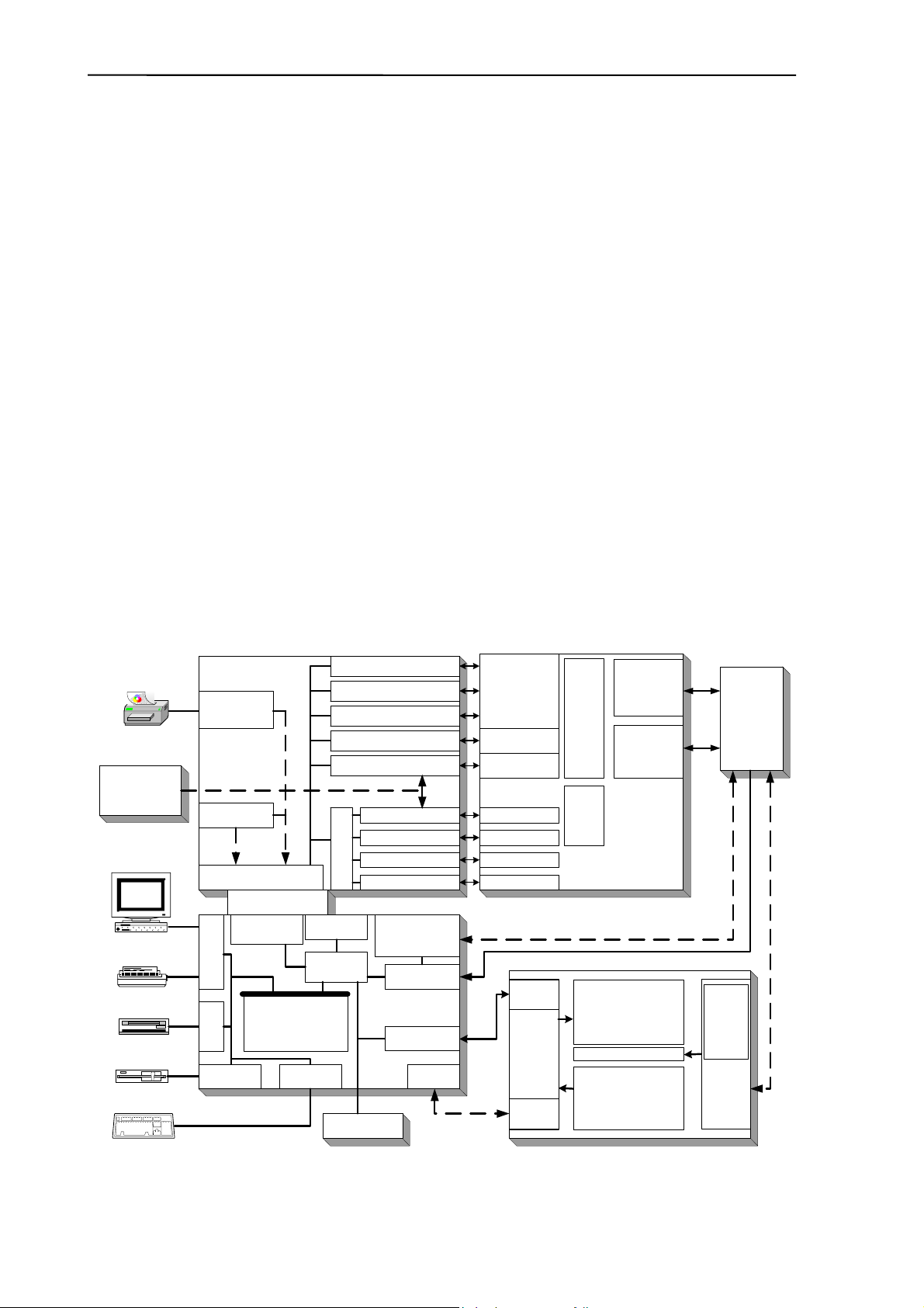
2. FUNCTIONAL DESCRIPTION
2.1. Main electronic parts of the analyzers
Abacus junior / Abacus junior vet contains the following electronic parts:
1. Counting chamber with electrodes and measuring aperture
2. HGB Measuring Head
3. Cell Counter Amplifier Board (behind the chamber)
4. CPU Board with Dimm-PC and measurement processing unit (COMB Board)
5. Safe configuration E
2
PROM board connecting CPU board and PPB
6. Pneumatic and Power Board with 6 motor controllers, valve & pneumatic controller,
pump driver and power supply for internal printer (+8V) and digital circuitry (+5V)
7. Motors with common opto-board of needle moving motors (H/V) and sample rotor
8. Main dilutor block with opto-board for diluent, lyse and rinse (AJVet)
9. Micro-dilutor block with opto-board for sampling
10. Valve boards (set of 5 and max. 7)
11. Peristaltic Pump
12. Pressure Sensor
13. Digital Reagent Sensor Board
14. Floppy Disk Drive and CD-ROM Drive (optional)
15. Graphic LCD Display Module with High Voltage Board
16. LCD and Keyboard controller and Keyboard Panel
17. Internal Printer
Serial No.
Config. Data
Cell
counter
amplifier
HGB I/F
Amplifier
LCD
Keypad
LCD Lamp
LCD and
Keypad
controller
High
Voltage
Board
+50V
+150V
Display Assembly
Optical
isolation
High
Voltage
Inverter
300V
AC
DC/DC
converter
Pneumatic I
2
C bus
Fluidic System
Counting
chamber with
electrodes
HGB
measuring
head
DC/DC
converter
+12V, -12V
Pneumatic and Power Board
Floppy drive
IDE I/F
Floppy I/F
Pneum I/F
LCD I/F
A/D converter
FPGA
Legacy I/O I/F
Dimm-PC
AMD Elan
SC-520
Configuration
microcontroller
CPU Board
Ext.Printer
Ext. Computer
Ext. Keyboard
CD-ROM Drive
IDEPROM
Pump driver
Valve drivers
Reagent sensor I/F
Pressure sensor I/F
Valve controller
Valve blocks
Pump
Pressure sensor
Reagent sensors
Opto board of
main dilutor
Opto board of
needle moving
motors H/V and
sample rotor
Opto board of
microdilutor
Motor controller/driver #1
Motor controller/driver #2
Motor controller/driver #3
Motor controller/driver #4&5
Motor controller/driver #6
Internal printer
power and I/F
+8V
Digital power
+5V
Power Board Interface
+5V, +12V, Pneum I
2
C
Keyboard I/F
Internal Printer
DC/DC converter
+12V / -12V
analog power
12Vdc External
Power Supply
Motors
Valves
12Vdc
START button
Status LEDs
Abacus junior / Abacus junior vet Electronic Functional Block Diagram

Abacus junior /vet / B Service Manual
Abacus junior B contains the following electronic parts:
1. Counting chamber with electrodes and measuring aperture
2. HGB Measuring Head
3. Cell Counter Amplifier Board (behind the chamber)
4. Motors with common opto-board of needle moving motors (H/V) and sample rotor
5. Main dilutor block with opto-board for diluent and lyse
6. Micro-dilutor block with opto-board for sampling
7. Valve boards (set of 5)
8. Peristaltic Pump
9. Pressure Sensor
10. Digital Reagent Sensor Board
11. Alphanumeric LCD Display Module with High Voltage Board
12. Keyboard Panel
13. Internal Printer
14. MAIN board
Serial No.
Config. Data
Real Time Clock
Battery
Cell
counter
amplifier
HGB I/F
Amplifier
LCD
(backlig ht internally
controlled)
Keypad
High
Voltage
Board
+50V
+150V
Display Assembly
Fluidic System
Counting
chamber with
electrodes
HGB
measuring
head
MAIN Board
LCD I/F
RS-232
Microcontroller,
CPLD and
some digital chips
Ext. Computer
(SW Uploader)
Pump driver
Valve drivers
Reagent sensor I/F
Pressure sensor I/F
Valve blocks
Pump
Pressure sensor
Reagent sensors
Opto board of
main dilutor
Opto board of
needle moving
motors H/V and
sample rotor
Opto board of
microdilutor
Motor driver #1
Motor driver #2
Motor driver #3
Motor driver #4 & #5
Motor driver #6
Internal printer
power and I/F
+8V
Power regulating
and filtering
+3.3V, +5V,
+8V, +12V,
Keyboard I/F
Internal Printer
Measurement
processing unit
and control I/F
12Vdc External
Power Supply
Motors
Valves
START button
Status LEDs
Abacus junior B Electronic Functional Block Diagram
Diatron Ltd. 2004
2.1.1. Counting chamber with electrodes and measuring aperture
Impedance method is used for determination of volume and number of cells. In this method a
known volume of dilution is drawn through a small aperture. Constant current is passed
through the aperture from one side to the other. When a cell passes through the aperture, it
causes a change in resistance, which generates a voltage pulse.
The amplitude of the voltage pulse is proportional to the ratio of cell volume per aperture
volume. This is used to determine the volume of cells. The number of cells can be obtained
by counting the pulses.
In the instruments there is one cell-counter probe: the aperture size is 80 µm and has a
reference electrode assembly and U-shaped metal fixing as it is shown in the figure below.
The aperture is made of ruby and it is molded into the measuring tube.
2.1.2. HGB Head
Hemoglobin head is placed around the measuring chamber in all instruments.
It contains: light source (LED) at 540 nm wavelength and Photo Detector (TSL235). The
Photo Detector converts the light to frequency. The HGB concentration is a logarithmic
function of this frequency measured by
• the FPGA circuit of the COMB card in AJ/AJvet
• the micro-controller of the MAIN board in AJB
Connection to the amplifier
LED
TSL235
ssembled Cell-counter Probe
Measuring tube
Measuring tube
Reference electrode
U-shaped metal fixing
Aperture (80µm)
O-ring
Abacus junior /vet / B Service Manual
9
The analyzers perform enhanced Hemoglobin measurement technology for HGB
measurement. The output of HGB head is frequency (TSL235 detector is light to frequency
converter). This signal is counted by a digital counter in the FPGA circuit/micro-controller.
This counter counts up while the LED is on and counts down while the LED is off, the LED
and the counter directions are switched with a 100 Hz signal. This method provides “real time
backlight correction”, which makes the HGB measurement more precise in changing
backlight environment situation as well.
There are two kinds of HGB measurements:
• Sample measurement (before RBC counting)
• Diluent measurement (in WBC washing phase)
The HGB result is calculated from these measurements by:
HGB ≅ log (CNT
diluent light
/ CNT
sample light
)
Due to enhanced HGB
technology, junior is less sensitive to incident light changes.
It is recommended to keep side door closed during measurements.
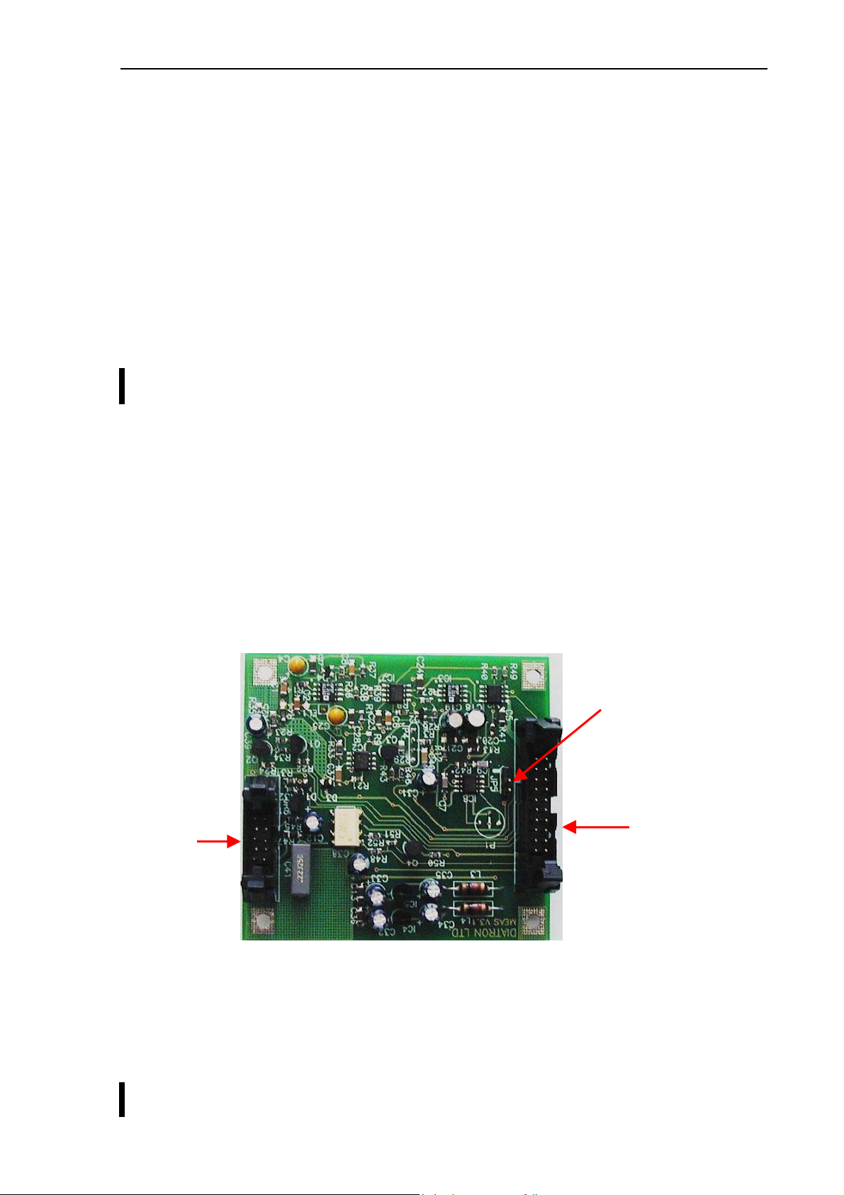
2.1.3. Cell counter Amplifier Board
Amplifier board includes its own voltage regulator, connection interfaces to HGB head, to
high voltage board and to COMB in AJ/AJvet (to MAIN in AJB). In this board there is a
current generator circuit, which works from 50V measuring voltage (generated by High
Voltage Board) and the probe voltage (DC) is amplified with a voltage follower (output: ELV).
Nominal measuring current is 870 µA.
Amplifier board includes one input connector for the chamber (measuring electrode). There
are two opto switches (U1, U3) to connect high voltage to the probe with HSW signal and
isolate the input of the amplifier. Test circuit makes possible to generate test pulses (with
TEST and PLS signals through FETs) for checking the proper operation of the amplifier
channel.
Amplifier board includes a 3-stage main amplifier channel, which gains input signal to the
0…5 V range (this is the input range of the A/D converter, which is placed on the COMB
card). The RSW signal changes the gain (RBC, WBC) in the feedback of the second
amplifier stage with U2 (MAX319) analog switch. There is an offset potentiometer, P1 in the
third amplifier stage, manufacturer sets the correct offset voltage.
Adjust the offset voltage only in case it is out of the +/- 5mV range.
Connection to:
CSA1 on COMB (AJ/AJvet)
CS_IMP on MAIN (AJB)
Connection
to HVB
Connection to:
CSA1 on COMB (AJ/AJvet)
CS_ANALOG on MAIN (AJB)
Diatron Ltd. 2004
1
DHON signal (from the COMB board — AJ/AJvet; from the MAIN board — AJB) switches on
the LED and the MVON signal – which is active during counting – switches off the Photo
Detector in the HGB head, to prevent noise generated by the HGB detector.
The other side of the amplifier board contains special connectors for the chamber and the
HGB head (JP4).
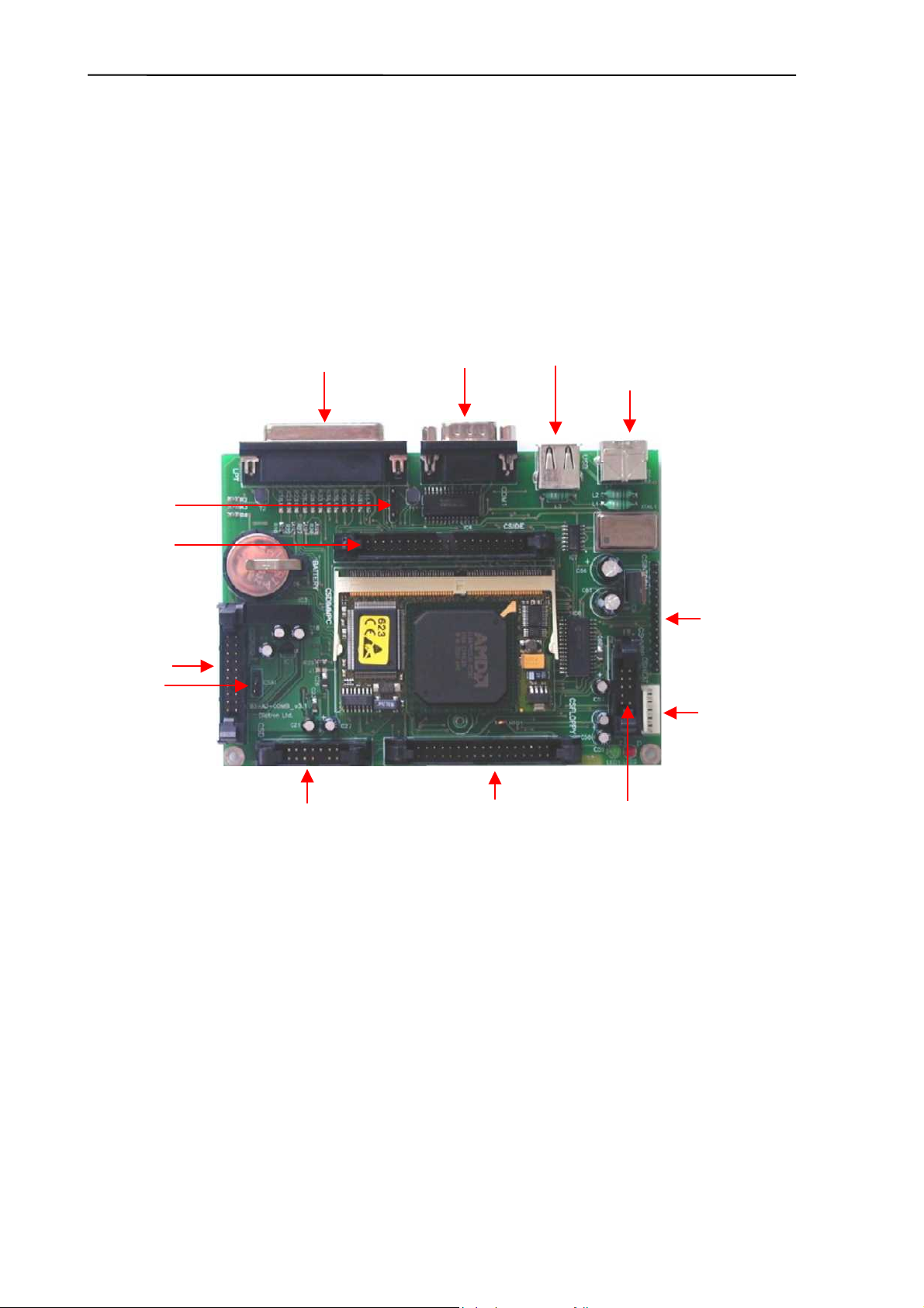
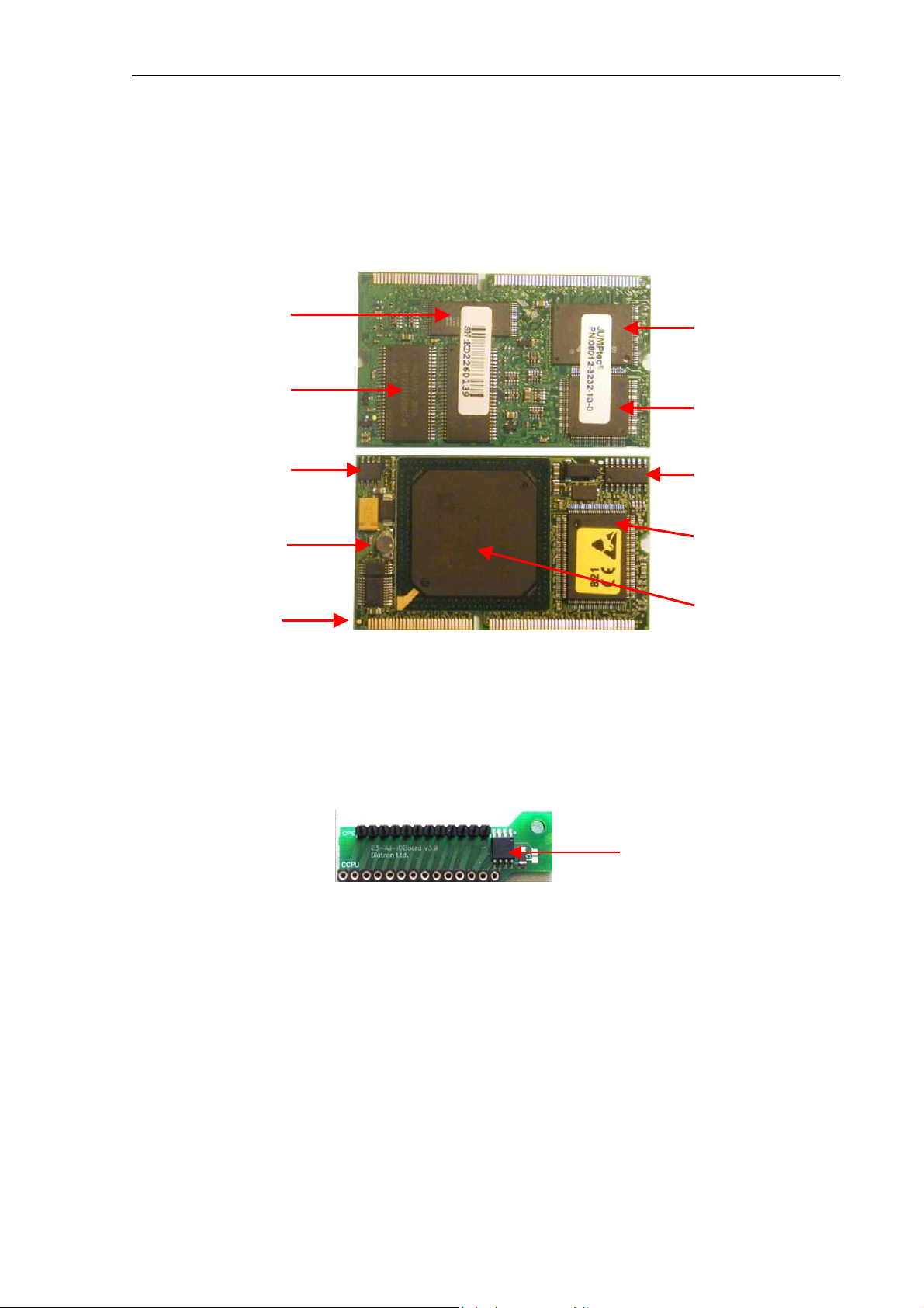
2.1.4. Control and Measurement Board (COMB) with Dimm-PC core — AJ/AJvet
The compact COMB incorporates a single PC and its environmental functions, as well as the
specific measurement processing functions in one board.
PC system of the COMB board is based on the Dimm-PC module, which is a credit card size
PC with AMD Elan SC520 133 MHz micro-controller. Dimm-PC itself contains 16 or 32Mbyte
RAM and same size of SanDisk that acts like a hard disk. Dimm-PC module is easily
replaceable as it has an open socket (it has also a screw for safe fixing). COMB card
contains single ICs and some drivers/protection-circuits for the interfaces such as LPT,
COM1, PS2, USB, IDE, Floppy and Speaker.
Measurement processing is based on FPGA circuit. After power on, FPGA holds the Dimm-
PC in wait state (with
–IOCHRDY signal) until the PIC configures the FPGA circuit from the
IDEPROM (status LED is red during configuration). After that the FPGA controls the entire
pneumatic system through the Pneumatic I
2
C bus, the Keyboard and Display module with
video RAM for MDA (Monochrome Display Adapter) emulation, and Start button & status
LED. FPGA circuit also performs measurement data acquisition by using the 10-bit A/D chip.
FPGA makes digital data processing and stores the results in the internal FIFO memory. Cell
parameters are sent to the Dimm-PC by single DMA cycles.
LPT port
COM port USB port
PS2 port
keyboard
Speaker
connection
CD-ROM
connection
CSDIGIO
CSA1
Amplifier
connections
CSD
Keyboard & Display and
Start key/LED connection
CSFLOPPY
Floppy
connection
CSHVBP
High voltage
board connection
CSHEAT
Reagent
heater
connection
CSINTCON
ID board
connection
Abacus junior /vet / B Service Manual
11
2.1.5. Dimm-PC* Module – AJ/AJvet
The MB4 board incorporates a credit-card sized PC, named Dimm-PC*. The processor on
the Dimm-PC is a 133MHz Pentium-class core, with 32Mbytes on-board RAM, and 32Mbytes
on-board SanDisk. This is the HDD (hard disk drive) of the analyzer, so instrument software
with all user settings, calibration, database, etc. is stored on the Dimm-PC.
* DimmPC® is the Trade Mark of Kontron Embedded Modules GmbH
2.1.6. Configuration and ID E
2
PROM board (IDEPROM) — AJ/AJvet
This board is the interconnection between COMB and PPB cards: Pneumatic I
2
C bus, power
lines and internal printer signals are connected through this card. The board also contains a
24FC256 serial E
2
PROM, which stores the FPGA’s configuration data and identity
information of the instrument (Serial Number, OEM, model, etc.).
Keeping the hardware identity information (write-protected), IDEPROM makes possible to
run the correct software (Human or Vet).
E
PROM
Flash BIOS
Edge connector
Super I/O
Hard Disk
(SanDisk)
CMOS EEPROM
Real-time clock
On-board SMPS
AMD Elan
SC520 CPU
32 Mbytes RAM
SanDisk
controller
Diatron Ltd. 2004
12
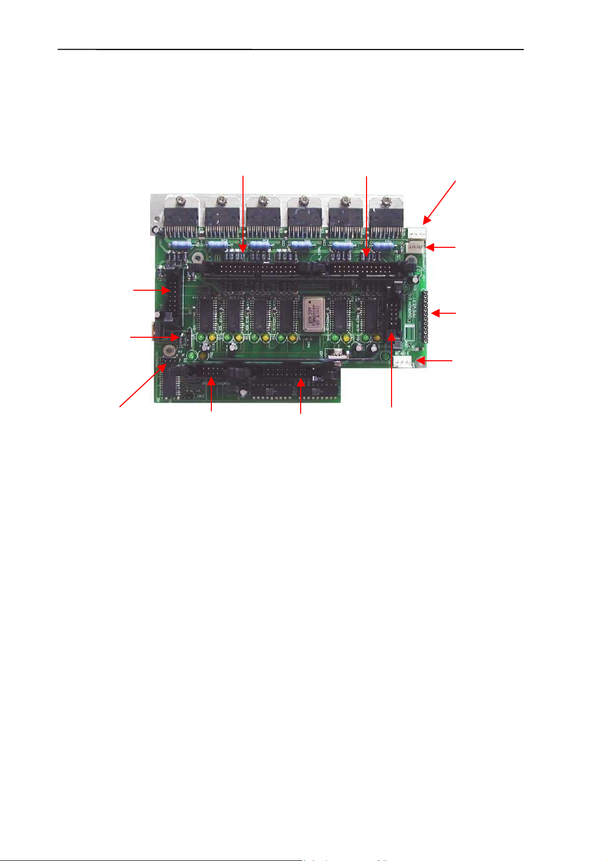
2.1.7. Pneumatic and Power Board (PPB) — AJ/AJvet
PPB card contains the main power regulator circuits, valve and motor driver circuits and
other connections for the fluidic and pneumatic system’s parts.
Power system generates +5V (Digital power), +8V (Printer power) and +12V (Motor and
valve power) from the single +12V DC input signal.
Motor driver part consists of six separated PIC micro-controllers with power drivers.
Horizontal, Vertical and Sample rotor motors have one combined ribbon cable connection.
Main Dilutor (with two motors) and Micro-dilutor have separated connectors.
Valve driver section is based on the valve driver PIC micro-controller and two 8-bit, powered
output shift registers (with built in protection diodes) and there is one common ribbon cable
connection for the valve boards. The peristaltic pump has a separated Darlington driver
circuit for more reliable operation.
2.1.8. Opto-boards for stepper motors
There are six stepper motors in the system: Horizontal and Vertical motors, which make the
movements of the sampling needle; the main Dilutor motors (2), which move the syringes
(macro, lyse, rinse); the micro Dilutor motor, which drives the sampling phase and the motor
moving the sample rotor. The stepper motor opto boards make the connections between the
motor driver ICs and motors, and have opto switches for the motor’s home and end
positions. The actual status of the stepper motor’s optos is indicated by two LEDs on each
stepper motor opto boards.
Dilutor and Micro-dilutor have its own separated opto-board, located directly in the units.
X_Y_SR
Horizontal, Vertical & Sample
rotor connection
FLOPPY/CD
Power to
Floppy/CD
PUMP
Peristaltic pump
connection
REAGENT_SENSOR
Reagent sensor
connection
VALVES
Valves connection
PRINTER
Internal printer
connection
+12V_IN
Power input
I_PCB_CONN
ID board
connection
DIL_MDIL
Main Dilutor
connection
PRESSURE
Pressure sensor
connection
MDIL
Micro dilutor
connection
5V voltage
regulator
(on chassis)
Abacus junior /vet / B Service Manual
13
Horizontal and Vertical motors and the sample rotor unit have a common Opto-board, called
XYOpto Board:
The other side of the board contains the connection for the Sample rotor and a ribbon cable
connection to the COMB (AJ/AJvet) or to the MAIN board (AJB).
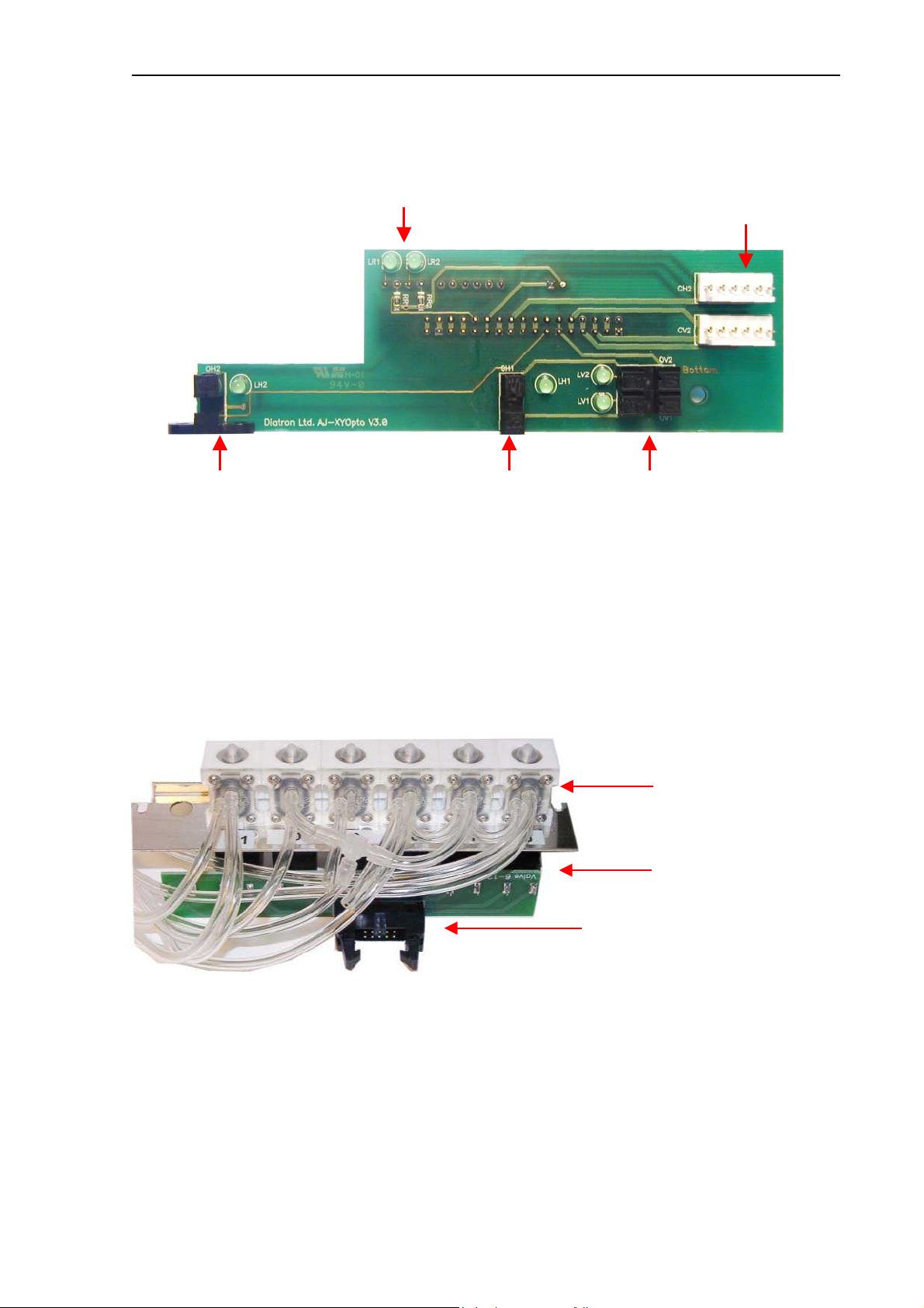
2.1.9. Valve boards
There are two kinds of valve boards: Valve board 1-5 and Valve board 6-12.
AJ
and AJB have 5 valves, while AJvet has 6 valves in Valve board 6-12 module. The
valve boards are connected to controller and driver chips are located on the PPB.
Opto switches & LEDs for Horizontal motor
Opto switches & LEDs for Vertical motor
LEDs for Sample rotor Connections for Hoirizontal &
Vertical motors
Valves
Valve Board
Connection to PPB
Diatron Ltd. 2004
14
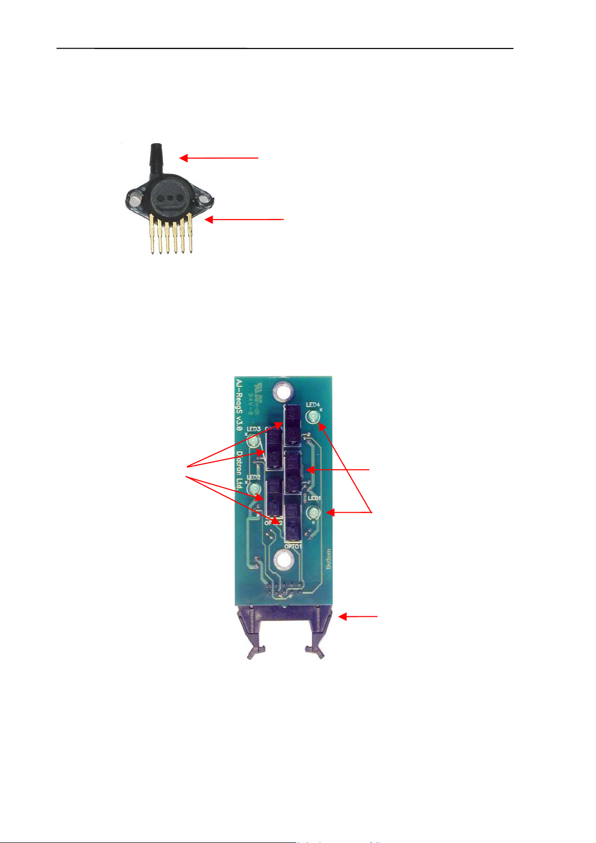
2.1.10. Pressure Sensor
This is an MPX5100AP calibrated pressure sensor, which can measure the required air
pressure and vacuum. The Pressure Sensor is connected directly to the PPB card (AJ/Ajvet)
or to the MAIN board (AJB).
The pressure sensor can operate from +5V only. It is a calibrated sensor with 0-1.1 Bar input
range. Do not apply more than 1.5 Bar to it, because it can ruin the pressure sensor.
2.1.11. Digital Reagent Sensor Board
This board contains four liquid detector opto-detectors (optos) and a reference opto for
automatic temperature and stray light compensation. The reference opto is located in the
middle and it has the same temperature and backlight conditions as the sensing ones.
The Reagent Sensor Board is connected to the PPB card in AJ/AJvet, and the valve driver
micro-controller makes the sensing and compensating operations. In AJB,
this board is
connected to the MAIN board and the micro-controller controls the operation of the Reagent
Sensor Board.
Instrument makes automatic initialization – called calibration – of reagent sensors during
priming phase of fluidics.
Connection to Puffer reservoir
Connection to:
PPB (AJ/Ajvet)
MAIN (AJB)
Reference detector
Reagent detectors
Control LEDs
Connection to:
PPB (AJ/Ajvet)
MAIN (AJB)
Abacus junior /vet / B Service Manual
1
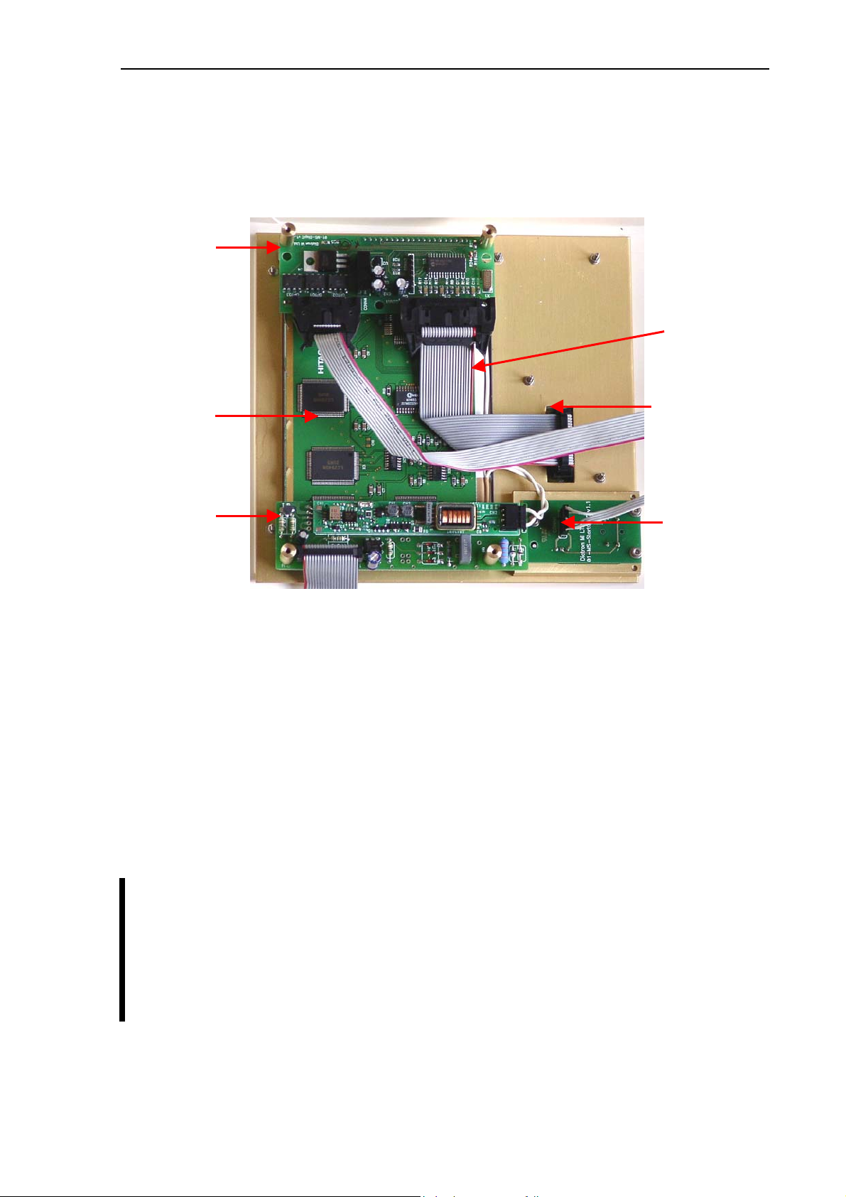
2.1.12. LCD Display Module with High Voltage Board of AJ/AJvet
Display assembly contains the 240×128 dots graphics LCD display and the high voltage
board. LCD has a high voltage backlight lamp (high voltage board generates the required
voltage).
There is a special temperature compensation circuit in the display module, which makes
possible to use the LCD module in wide temperature ranges with the adjusted contrast.
High Voltage Board (HVB) generates LCD backlight voltage (300V), aperture cleaning
voltage (150V), and measuring voltage (50V). The high voltage board is connected to the
system through the amplifier board and the COMB card. This unit contains INVC191 inverter,
which is a high voltage, high frequency circuit producing suitable voltage for CCFL (cold
cathode fluorescent lamp) of the LCD.
The CFSW digital signal (from the COMB card) controls HVB: logical LOW turns inverter on.
The MVON digital signal (from the COMB card) switches the measuring voltage (50 V) on/off
by O1 opto switch.
Warning! Be careful with servicing this board in active state, because the high
voltage (300V) at LCD lamp connector can cause damages or electric shock.
Never operate the analyzer without the LCD backlight connected to the HVB,
because the over-voltage on the output of the HVB can damage the HVB board and
the amplifier.
LCD &
Keypad
controller
LCD module
Keypad connector
HVB with
inverter
Start key and
status LED board
LCD backlight
lamp
Diatron Ltd. 2004
1
In Abacus Junior B, we needed a new high voltage board, because in this instrument there’s
no need for the inverter on the previous HVB (the alphanumeric display has no CCFL
backlight), but the measuring and cleaning voltage generation based on the inverter’s high
voltage. That’s why we developed HVB v2.1, which is still capable to carry and feed the
inverter, but the board has its own high voltage generation circuitry, so can be used without
the inverter placed on it.
HVB v2.1:
Start key is a micro-switch, connected to the COMB card (through the Display ribbon cable).
The status LED indicates the actual status of the analyzer and it has three colors: red, green
and amber (See User’s Manual). The LED has three pins and the actual color depends on
the controlled pins. Start key and status LED are controlled by COMB.
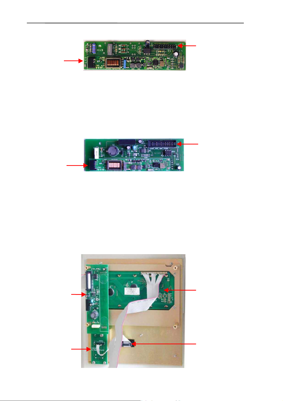
2.1.13. LCD Display Module with High Voltage Board of Abacus Junior B
The display assembly in Abacus Junior B contains a 4×20 characters alphanumeric display,
a high voltage board, a Start key and status LED board. The alphanumeric display has
internal LED based backlight, which is driven and controlled by the MAIN board.
Connection
to LCD lamp
Connection to
COMB and
amplifier
Start key and status
LED board
Alphanumeric LCD
HVB
without inverter
Keypad connector
Connection
to LCD lamp
Connection to
COMB and
amplifier
Abacus junior /vet / B Service Manual
1
High Voltage Board (HVB) generates the aperture cleaning voltage (150V), and measuring
voltage (50V). The high voltage board is connected to the system through the amplifier board
and the MAIN board.
CFSW signal (from MAIN board) controls HVB: logical LOW turns inverter on. MVON signal
(from MAIN board) switches the measuring voltage (50 V) on/off by O1 opto switch.
Warning! Be careful with servicing this board in active state, because the high
voltage can make damages or electric shock!
Start key is a micro-switch, connected to the MAIN board (through the Display ribbon cable).
The status LED indicates the actual status of the analyzer and it has three colors: red, green
and amber (See User’s Manual). The LED has three pins and the actual color depends on
the controlled pins. The MAIN board controls start key and status LED.
In Abacus Junior B the LCD controlling and keypad reading are handled by the micro-
controller of the MAIN board via some interface circuitry.
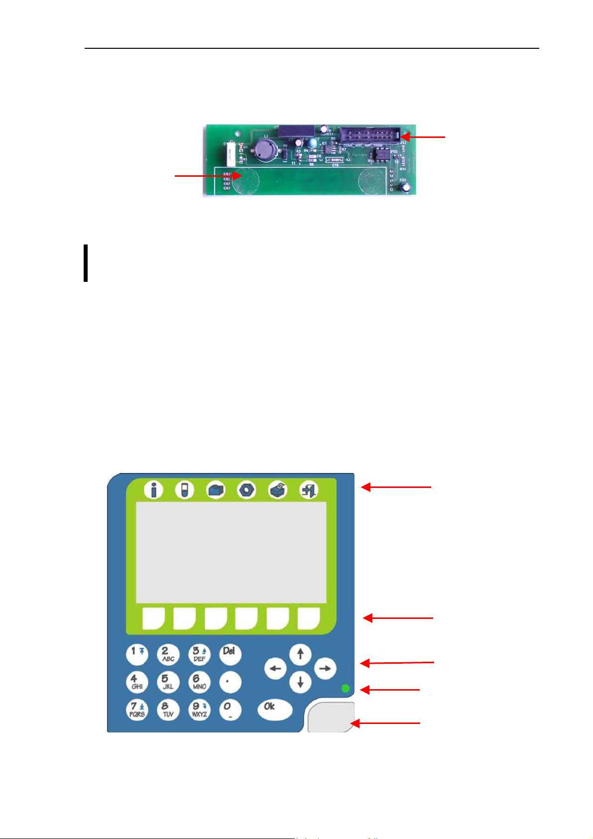
2.1.14. Keypad of Abacus junior/Abacus junior vet
The analyzer has a 29-button foil keypad including numerical keypad (0-9, “.”), cursor
moving, OK and Del buttons, and 6-6 function buttons, above and under the LCD display as
it is shown in the picture below:
Cursor buttons
START button
Status LED
Function buttons
Function buttons
Connection to
MAIN board
Uninstalled
inverter board

Diatron Ltd. 2004
1
2.1.15. Keypad of Abacus junior B
The analyzer has a 21-button foil keypad including numerical keypad (0-9, “.”), OK and Del
buttons, and 4-4 function buttons, above and under the LCD display as it is shown in the
picture below:
2.1.16. Floppy Disk Drive and CD-ROM Drive — AJ/AJvet
The built-in Floppy Disk Drive makes possible to save data on floppy disks, and to install (or
upgrade) the software. The optional CD-ROM drive can be used to install software (only read
actions from CD-ROM, as write operations are not supported by the instrument’s operating
system). Both units are connected to COMB card: CD-ROM to IDE interface, FDD to Floppy
interface.
CD-ROM
Drive
Floppy Disk
Drive
Function buttons
Function buttons
Status LED
Start button
Abacus junior /vet / B Service Manual
19
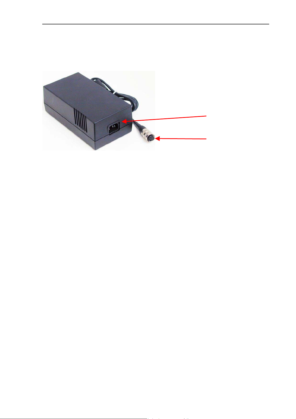
2.1.17. External Power Supply
The analyzer works with an external power supply. The next figure shows the power supply
unit generating 12VDC.
The power supply modules have an auto range input, which makes possible to use them with
230V or 115V mains outlet and it has the CE and UL safety certification. The input socket of
the power supply is a standard 3-terminal plug, with power cable connection; the output is a
special, lockable socket as it is shown in the picture.
2.1.18. MAIN board — AJB
MAIN board is responsible to control the instrument: contains the main power regulator
circuits, valve and motor driver circuits and other connections for the fluidic and pneumatic
system’s parts, responsible for the specific measurement processing functions.
The board also contains two 24FC256 serial E
2
PROMs, which store the settings and identity
information of the instrument (Serial Number, OEM, model, etc.) and the measurement
database.
The central micro-controller with a CPLD and with several other digital chips (buffers,
decoder, multiplexer) handles the pneumatic system, displaying, measurement and data
management.
Power system: filtering the +12V Input and generates +3.3V (CPLD), +5V (Digital power),
+8V (Printer power). Filtered +12V is used for the power of motors and valves.
Motor drivers: 6 power drivers; Horizontal, Vertical and Sample rotor motors have one
combined ribbon cable connection. Main Dilutor (with two motors) and Micro-dilutor have
separated connectors.
Valve driver: consists two 8-bit, powered output shift registers (with built in protection diodes)
and there is one common ribbon cable connection for the valve boards. The peristaltic pump
has a separated Darlington driver circuit for more reliable operation.
Real Time Clock: for TIME/DATE functions; powered by Battery at switched off state.
Measurement processing: the A/D conversion made by the micro-controller itself, but several
preprocessing steps (time limits, noise handling, pulse integration) taken by the external
analog circuitry.
External communication through RS232 makes possible to update the firmware of the micro-
controller with an external PC.
115V or 230V
AC inlet
12V DC outlet

Diatron Ltd. 2004
2
COM port
Speaker
connection
LCD, Keypad and
Startkey/LED
connection
CS_ANALOG and CS_IMP
amplifier connections
High Voltage
Board
connection
Micro
dilutor
connection
Peristaltic
Pump
connection
Pressure
sensor
connection
Reagent
Sensor
connection
Valves
connection
+12V
Power Input
Printer
connection
+5V voltage
regulator
(on chassis)
Main Dilutor
connection
Horizontal, Vertical & Sample
rotor connection
Abacus junior /vet / B Service Manual
21
2.2. Main mechanic and fluidic parts of the Analyzer
Abacus junior / Abacus junior vet / Abacus junior B Hematology Analyzers consist of the
following mechanic and fluidic parts:
1. Sample rotor
2. Sampling needle
3. Washing head
4. H&V moving unit
5. Micro Dilutor
6. Dilutor
7. Chamber
8. Cell-counter probe
9. Puffer reservoir
10.Pump
11.Valves
12.Tubing
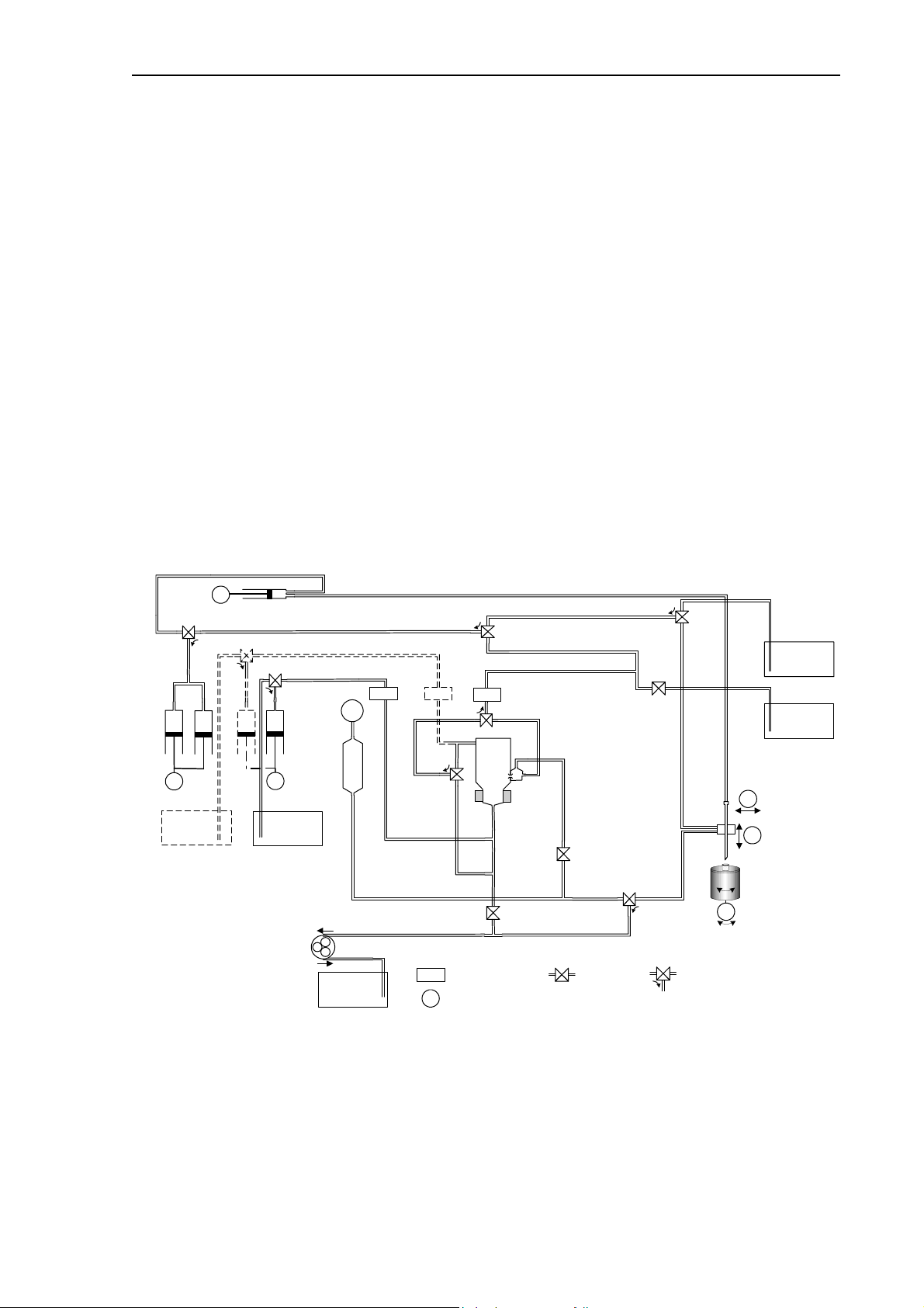
HGB
Abacus
junior
&
Abacus junior vet
&
Abacus junior
B
Fluidic Schematics
Version 2.1
WASTE
CLEANER
M2
M1
P
V10 Cleaner
V4 DilAperture
V2 DrainAperture
V1 DrainChamber
V6 DilWash
RBC
WBC
V5 DrainPuffer
M1
LDx
Liquid Detector
Stepper Motor
2-way Valve
Closed = Off
Open = On
12
3
3-way
Valve
1-3 = Off
2-3 = On
1
2
3
1
2
3
Pump
Hor
Ver
1
2
3
Puffer
Reservoir
Pressure
Meter
Lyse
Sensor
Diluent & Cleaner
Sensor
1
2
3
LDD
V3 Bubble
1
2
3
Micro-dilutor
DILUENT
1
2
3
V7 DilChamber
M5
LDRLDL
Rinse
Sensor
Sample
rotor
LYSE
V8 DilNeedle
V9LyseWbc
1
2
3
Lyse
Dil
M3
RINSE
Rinse
1
2
3
V11Rinse
M6
M4
Main
dilutor
The main fluidic schematics are almost the same for the three models. The only exception is
the Rinse reagent and the corresponding Rinse syringe and Rinse valve (V11), which is
present for the AJvet model only.
Diatron Ltd. 2004
22
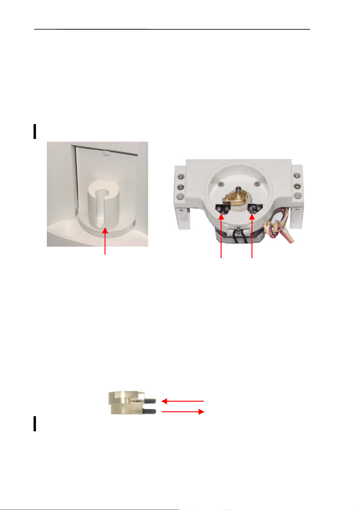
2.2.1. Sample rotor
Abacus junior / Abacus junior vet / Abacus junior B hematology Analyzers has a sample
rotor for safety and more precise sample handling. Commonly used sample tubes are
supported by replaceable tube adapters.
The Sample rotor unit uses a stepper motor, connected to the PPB (AJ/AJvet) or to the
MAIN board (AJB), through the XY opto board. The rotor has micro switches for positioning.
The unit blocks itself in the home and end position with mechanical parts and has a special
cap that prevents the damage of the electronic and mechanic parts caused by any fluid.
Sample rotor is maintenance-free.
2.2.2. Sampling needle
Sampling needle is assembled in the H&V moving unit and it makes the sample aspirations.
Correct setting of sampling needle is necessary and very important (see Chapter
Adjustments).
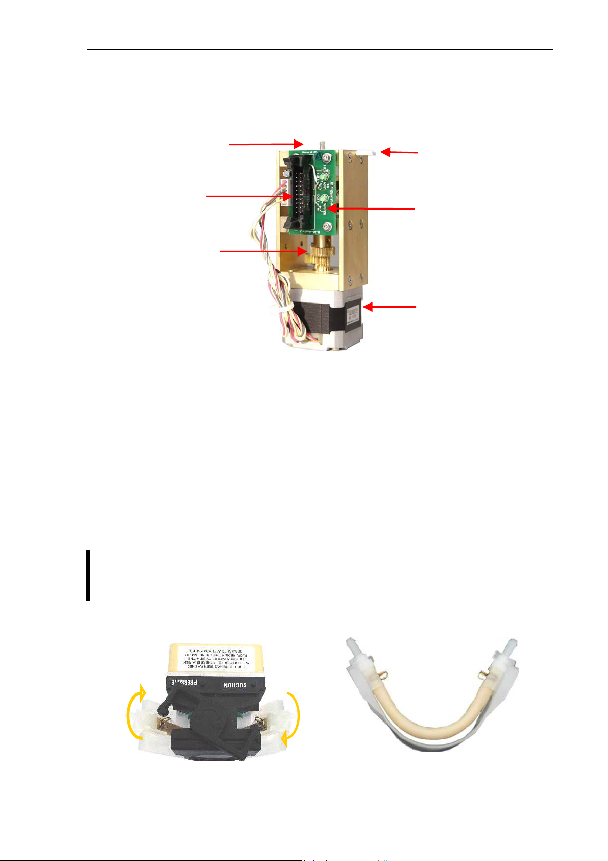
2.2.3. Washing head
Washing head is located at the bottom of the H&V moving unit and it is for cleaning the outer
surface of the sampling needle. This washing process is made with diluent reagent and the
fluid is drained by the pump. The arrows on the picture show the direction of diluent flow
during sampling needle washing.
Clean or replace washing head yearly, or after 10 000 measurements.
Replaceable tube adapter Micro switches for positioning
Clean diluent
Pump to waste
Abacus junior /vet / B Service Manual
23
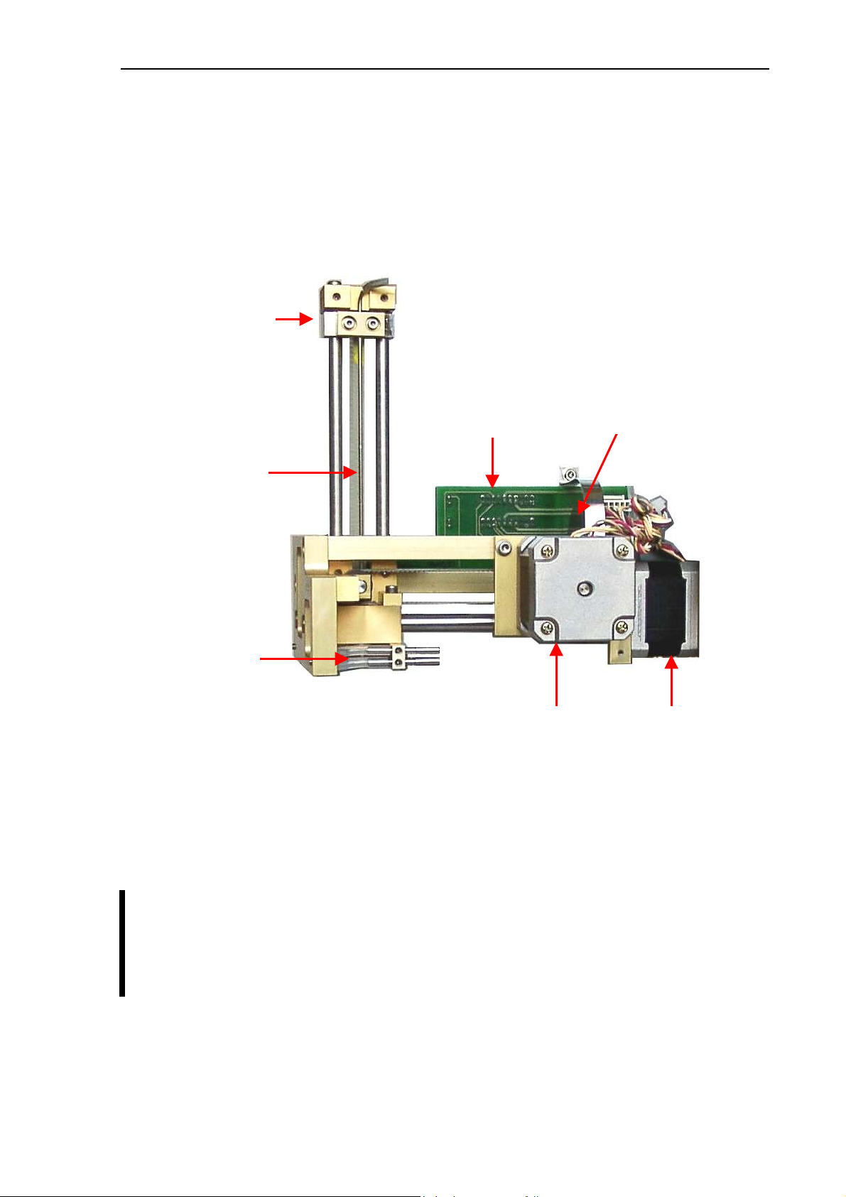
2.2.4. H&V moving unit
All three instruments use the same H&V moving unit.
This unit contains slides to move the sample sampling needle in Horizontal and Vertical
directions, two stepper motors, XYR opto board, opto wheel, washing head and the sampling
needle. It moves the needle to the desired position: from sampling position, to washing head,
and to the measuring chamber.
Both stepper motors have optical end-switch sensors for detecting these positions. These
are required for correct initialization and error detection. All sensors have status LEDs to
show actual conditions.
The Vertical motor works with a special opto wheel for detecting home & end positions. See
the Adjustment section of this manual to place this wheel to the proper position.
Greasing of the horizontal/vertical guiding rods should be done regularly using
“Photorub”, a PTFE-based thin lubricant.
It is recommended to check and repeat greasing of guiding rods every year, or after
10000 measurements.
Sampling needle
holder
XYR opto board
Horizontal
motor
Vertical
motor
Sampling needle
Washing head
Vertical opto wheel
Diatron Ltd. 2004
24
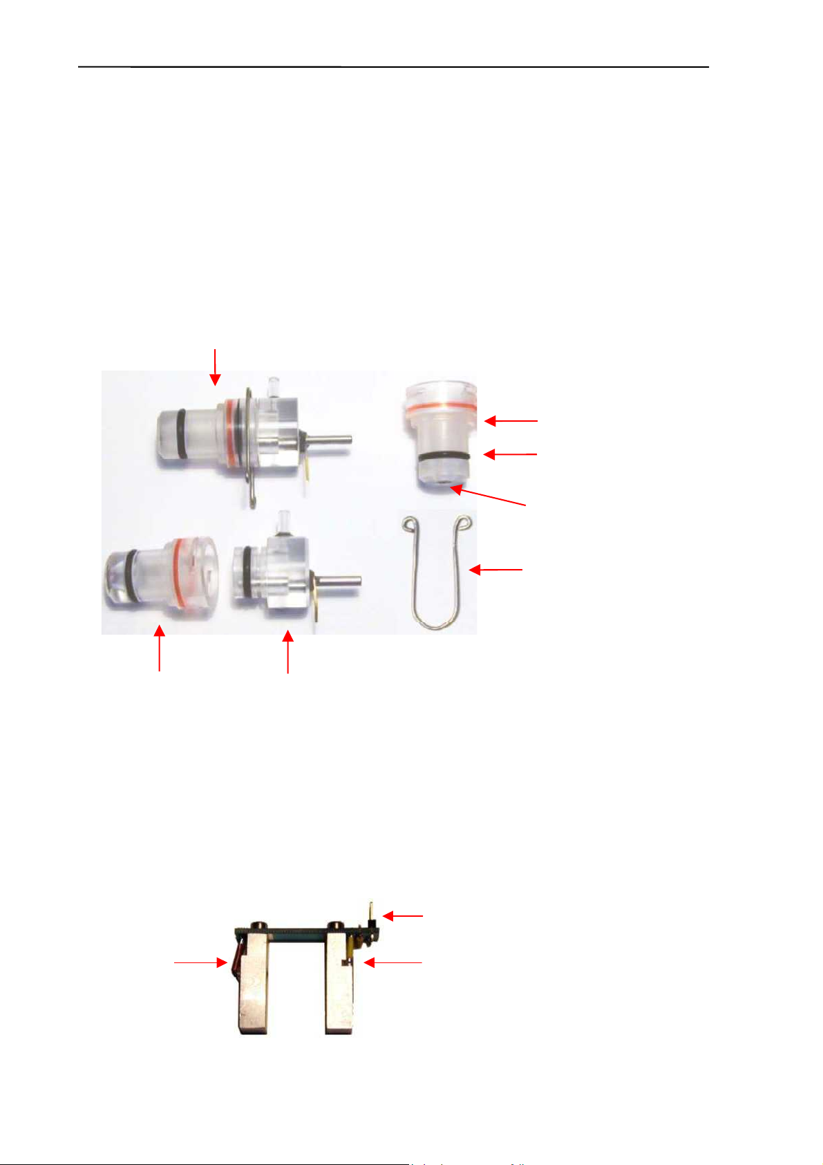
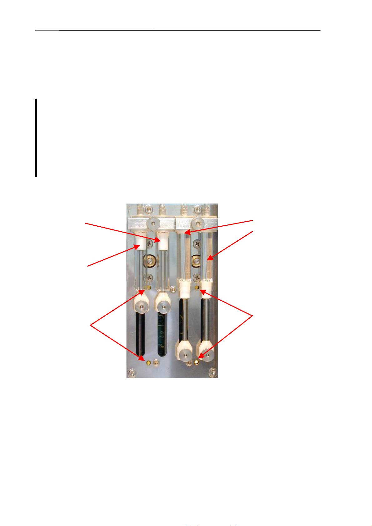
2.2.5. Main Dilutor
In case of AJ and AJB this unit includes two dilutor channels – one for diluent, and another
one for lyse reagents. (There’s another channel for Rinse in the AJvet model). There are two
stepper motors, a common motor opto board, three (AJ/AJB) or four (AJvet) syringes and
piston rods with gear transmission.
Maintenance should be provided to the piston tips, by applying neutral silicon
grease to the cogged end of the Macro and Lyse pistons, between the syringe and
the tip itself. This will ensure optimum sealing and longer lifetime of piston tips.
Greasing of the cogged transmission parts (cogwheel and cogged bar) should be
done regularly using machine grease.
It is recommended to check and repeat greasing of piston tips, and transmission
gear every year, or after 10000 measurements.
Diluent
syringes
Rinse
piston
AJvet
Lyse
piston
Control
LEDs
Control
LEDs
Abacus junior /vet / B Service Manual
2
2.2.6. Micro Dilutor
Micro dilutor is taking the precise sample (25 or 50µl) into the sampling needle. It includes a stepper
motor, a motor opto board and the micro syringe.
2.2.7. Puffer reservoir
The glass puffer reservoir is directly connected to the pressure sensor.
During measurement, there is no pump activity, so the puffer reservoir maintains measuring
vacuum stable. The instrument measures atmospheric pressure and adjusts measuring
vacuum according to it.
2.2.8. Pump
Pump generates regulated vacuum and drains the fluidic system. It is connected to the PPB
(AJ/AJvet) or to the MAIN board (AJB) and it has its own driver circuit (Darlington).
If the tube of the peristaltic pump becomes worn, it can be broken, causing Pressure error.
It is recommended to check the state of the tube, and replace it every 2 years, or
after 20 000 measurements. Always replace the peristaltic pump tube to the same
PharMed® type, with the same length.
For servicing the tube of the pump, open the peristaltic pump from its top (see picture) and
remove the tube together with the white plastic side wall (see picture):
In case of damaged tubes, it can be replaced by a new one by opening the two metal locks
located at the two ends of the tube (see picture).
Connection to
PPB (AJ/AJvet)
MAIN board (AJB)
Transmission gear
Stepper motor
Connection to needle
Connection to Valve
Motor opto board
Diatron Ltd. 2004
2
2.3. Assembled Analyzer
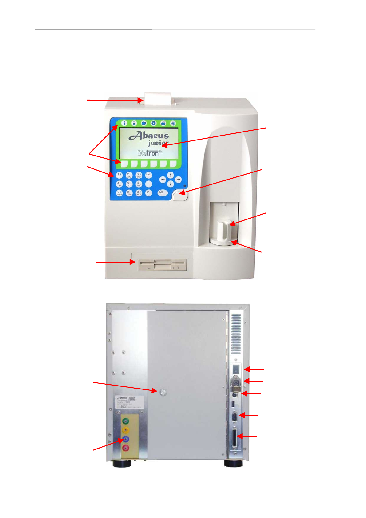
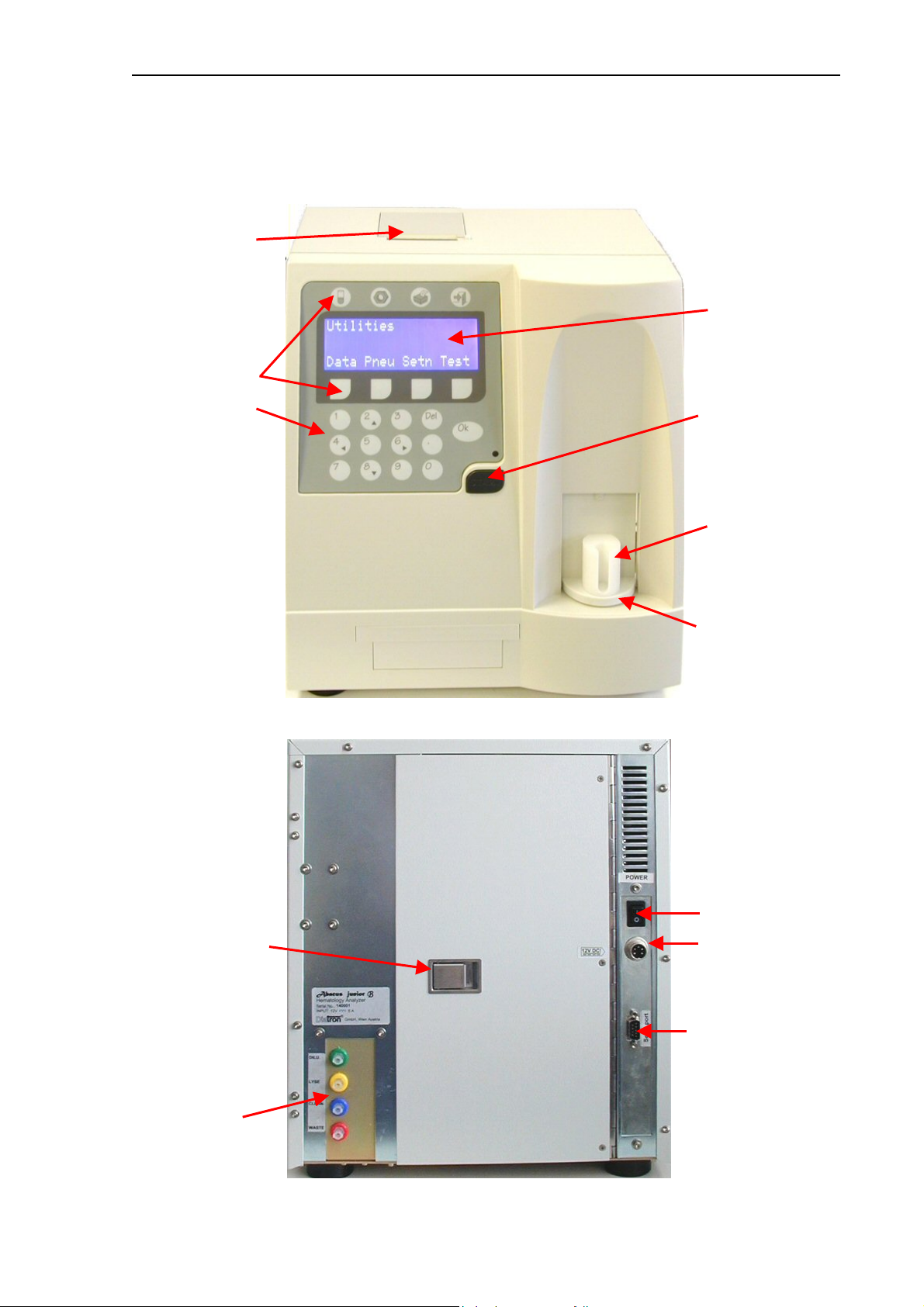
2.3.1. Abacus junior / Abacus junior vet
Front Panel (note display logo: it is an Abacus Junior model; and missing optional CD-ROM
drive module):
Rear panel (note reagent inlets: it is an Abacus Junior model as there is no Rinse
connection):
240×128 dots
Graphic LCD
Floppy drive
Built-in thermal
printer (optional)
Sample tube
adapters
Sample rotor
START button
Function keys
Foil keypad
Reagent inlets
Serial Port
Printer Port
Back door to
access pump and
main dilutor
Keyboard
Power switch
Abacus junior /vet / B Service Manual
2
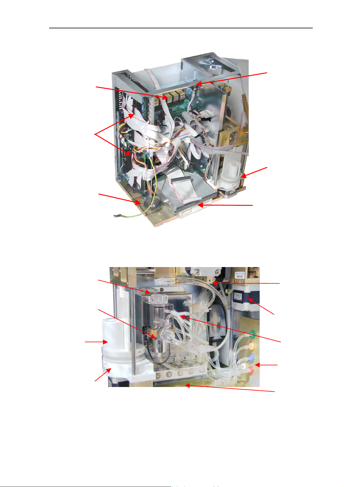
Construction – front (note optional CD-ROM drive):
Construction – right side (note white reagent inlet for Rinse: it is an Abacus Junior Vet
model):
Chamber and
aperture
Micro dilutor
Washing head
Amplifier
assembly
Reagent
inlets
Valve block
Adapter
Sample rotor
Needle
moving
mechanics
Speaker
CD-ROM, FDD
Sample rotor
Electronic
block
Pressure
sensor
Valve block
Diatron Ltd. 2004
2
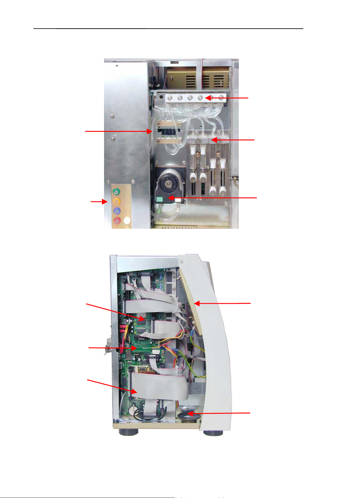
Construction – back (note white reagent inlet for Rinse, main dilutor and valve block with 6
valves: it is an Abacus Junior Vet model):
Construction – left side (note connected IDE ribbon cable):
Reagent
connectors
Valve block
Reagent
sensors
Main Dilutor
Peristaltic
pump
Display
assembly
Pneumatic
and Power
Board (PPB)
Control and
Measurement
Board (COMB)
Speaker
ID Eprom Board
IDEPROM
Abacus junior /vet / B Service Manual
29
2.3.2. Abacus junior B
Front panel (note missing floppy and CD-ROM drives):
Rear panel (note Serial Port as the only interface):
4×20 character
Alphanumeric LCD
Built-in thermal
printer
Sample tube
adapters
Sample rotor
START
button
Function keys
Foil keypad
Reagent inlets
Serial Port
Back door to
access pump and
main dilutor
Power switch

Diatron Ltd. 2004
3
Construction – front:
Construction — right side:
Speaker
Sample rotor
Electronic
block
Pressure
sensor
Valve block
Chamber and
aperture
Micro dilutor
Washing head
Amplifier
assembly
Reagent
inlets
Valve block
Sample rotor
Needle
moving
mechanics

Abacus junior /vet / B Service Manual
31
Construction – back (note valve block with 5 valves):
Construction — left side:
Reagent
connectors
Valve block
Reagent
sensors
Main Dilutor
Peristaltic
pump
Display
assembly
Speaker
MAIN board

Diatron Ltd. 2004
32
3. OPERATION OF THE FLUIDIC SYSTEM
This section describes the main fluidic steps of Abacus junior / Abacus junior vet /
Abacus junior B measurement cycle. The instrument’s Fluidic Schematics are shown in
Section 2.2. of this manual. The following figures show total measurement flow diagram and
detailed descriptions of processes for understanding the fluidic system work.
The following steps are introduced in this section:
1. Flow diagram of measurement
2. Initialization process
3. Sampling process
4. Needle washing process
5. Diluting process
6. Lysing process
7. Counting process
8. Chamber draining process
9. Cleaning process
10. Shutdown process
In the detailed process description figures, the active tube is filled with black color, while an
arrow (
→) shows the direction of the flow. Moving mechanic parts have another arrow
indicating direction of movement. Only opened (On) valves are mentioned in this section
while all the other valves are closed (Off).
Abacus junior / Abacus junior vet / Abacus junior B employs a software waste full
checking feature. Software integrates volume of the reagents used, and gives a message
when this volume reaches the preset tank capacity.

Abacus junior /vet / B Service Manual
33
3.1. Flow diagram of measurement
Previous RBC
dilution in chamber
Diluent of washing
process in chamber
6 ml
Diluent of standby
state in chamber
3 ml
Chamber draining
h
m
r fl
h
Fill up with 1 ml
diluent for WBC
dilution
Horizontal motor
moves out, sample
rotor turn in, needle
moves down
Sampling process
Needle washnig,
needle positioning
into the chamber
First dilution (1:160)
WBC only?
Needle washing
RBC sampling
Lysing process
Filling of electrode
lines; generating
measurin
vacuum
H
B m
r
m
n

Diatron Ltd. 2004
34
Lyse2 > 0 ?
A
vet
High voltage
cleaning pulses;
backflush
Lysing process
Measuring vacuum
WBC2
measurement
Lyse retract
Small washing
Cleaning (cleaner)
High voltage
cleaning pulses;
backflush
Vet?
Washing (diluent)
Blank HGB
measurement

Abacus junior /vet / B Service Manual
3
WBC only?
Fill up with 1 ml
diluent for RBC
dilution
RBC dilution
(1:32000)
Filling of electrode
lines; generating
measurin
vacuum
RB
m
r
m
n
Rinse (1,6 ml);
waiting (5 sec)
Motor
synchronizations
RBC2 ?
(AJvet)
RB
2 m
r
m
n
End

Diatron Ltd. 2004
3
3.2. Initialization of the Fluidic System
Fluidic initialization process performs the following steps:
• Checking of valves by turning all on/off
• Checking of pump and pressure sensor by generating measuring vacuum
• Positioning all mechanical components by scanning moving range (with end-
switches)
• Priming of reagents and calibrating reagent sensors
• Cleaning of tubing & measuring chamber
• Cleaning of aperture with high-pressure back-flush, cleaner reagent & high-voltage
burning
3.3. Sampling process
The aspirating needle aspirates 25 µl (50 µl in prediluted mode) of blood sample. The Micro-
dilutor syringe makes the aspirating while the M4 Micro-dilutor motor moves down.
There is also another sampling process for the second (RBC) dilution, 25 µl of primary
dilution is aspirated by the sampling needle from the chamber but it is kept in the sampling
needle during the WBC measurement and the cleaning process.
HGB
WASTE
CLEANER
M2
M1
LYSE
P
V8 DilNeedle
V9 LyseWbc
V10 Cleaner
V4 DilAperture
V2 DrainAperture
V1 DrainChamber
V6 DilWash
RBC
WBC
V5 DrainPuffer
M1
LDx
Liquid Detector
Stepper Motor
2-way Valve
Closed = Off
Open = On
12
3
3-way Valve
1-3 = Off
2-3 = On
1
2
3
1
2
3
1
2
3
Lyse
Pump
Dil
Hor
Ver
1
2
3
Puffer
Reservoir
Pressure
Meter
Lyse
Sensor
Diluent & Cleaner
Sensor
1
2
3
LDD
V3 Bubble
M3
1
2
3
Macro
Micro-dilutor
1
2
3
Rinse
RINSE
DILUENT
1
2
3
V11 Rinse
V7 DilChamber
M5
LDRLDL
Rinse
Sensor
Sample
rotor
M4

Abacus junior /vet / B Service Manual
3
3.4. Needle washing process
Both instruments clean the sampling needle with diluent in the washing head after sampling.
It is important to clean the outer surface of the sampling needle to avoid inaccurate sampling.
The Macro syringe doses and the pump drains the diluent from the washing head, while the
sampling needle moves upwards so that the total length of it is washed and cleaned. This
process is called total sampling needle washing, and it is mainly used after taking primary
sample from sample tube.
Another process, which is washing only a smaller part of the sampling needle, is the same
but the needle does not move in the total length. Some procedures perform this kind of
sampling needle washing.
The Macro syringe pushes the diluent through V8 (Off), V7 (Off), V6 (On). The Pump
aspirates the diluent from the washing head through V5 (On), while the M2 Vertical motor
moves the sampling needle up.
HGB
WASTE
CLEANER
M2
M1
LYSE
P
V8 DilNeedle
V9 LyseWbc
V10 Cleaner
V4 DilAperture
V2 DrainAperture
V1 DrainChamber
V6 DilWash
RBC
WBC
V5 DrainPuffer
M1
LDx
Liquid Detector
Stepper Motor
2-way Valve
Closed = Off
Open = On
12
3
3-way Valve
1-3 = Off
2-3 = On
1
2
3
1
2
3
1
2
3
Lyse
Pump
Dil
Hor
Ver
1
2
3
Puffer
Reservoir
Pressure
Meter
Lyse
Sensor
Diluent & Cleaner
Sensor
1
2
3
LDD
V3 Bubble
M3
1
2
3
Macro
Micro-dilutor
1
2
3
Rinse
RINSE
DILUENT
1
2
3
V11 Rinse
V7 DilChamber
M5
LDRLDL
Rinse
Sensor
Sample
rotor
M4

Diatron Ltd. 2004
3
3.5. Diluting process
The parts of the fluidics are rinsed with diluent reagent. The measuring chamber is filled up
with 1 ml of diluent. This method prevents the chamber from dirt and makes the diluting
process faster.
The sampling process has aspirated 25 µl of sample, which is in the sampling needle. In the
first diluting step the sample is dispensed into the measuring chamber with 3 ml of diluent,
which comes from the Macro syringe through V8 (On) and Micro-dilutor, while the M3 Dilutor
motor moves upwards. This process makes the 1:160 first dilution rate in the chamber.
The second sample – 25 µl of primary dilution – is stored in the sampling needle during the
WBC measurement and the cleaning process. The instrument makes the second (RBC)
dilution into the chamber after these processes.
HGB
WASTE
CLEANER
M2
M1
LYSE
P
V8 DilNeedle
V9 LyseWbc
V10 Cleaner
V4 DilAperture
V2 DrainAperture
V1 DrainChamber
V6 DilWash
RBC
WBC
V5 DrainPuffer
M1
LDx
Liquid Detector
Stepper Motor
2-way Valve
Closed = Off
Open = On
12
3
3-way Valve
1-3 = Off
2-3 = On
1
2
3
1
2
3
1
2
3
Lyse
Pump
Dil
Hor
Ver
1
2
3
Puffer
Reservoir
Pressure
Meter
Lyse
Sensor
Diluent & Cleaner
Sensor
1
2
3
LDD
V3 Bubble
M3
1
2
3
Macro
Micro-dilutor
1
2
3
Rinse
RINSE
DILUENT
1
2
3
V11 Rinse
V7 DilChamber
M5
LDRLDL
Rinse
Sensor
Sample
rotor
M4

Abacus junior /vet / B Service Manual
39
3.6. Lysing process
In this step the set lysing reagent is added into the measuring chamber through V9 (On),
while the Lyse syringe moves upwards. This process makes the WBC/HGB dilution with lyse
reagent.
For better mixing the macro syringe pushes some air bubbles (aspirated through the washing
inlet of the chamber and V3) after the lysing process through V8 (Off), V7 (On), V4 (Off) V3
(On).
HGB
WASTE
CLEANER
M2
M1
LYSE
P
V8 DilNeedle
V9 LyseWbc
V10 Cleaner
V4 DilAperture
V2 DrainAperture
V1 DrainChamber
V6 DilWash
RBC
WBC
V5 DrainPuffer
M1
LDx
Liquid Detector
Stepper Motor
2-way Valve
Closed = Off
Open = On
12
3
3-way Valve
1-3 = Off
2-3 = On
1
2
3
1
2
3
1
2
3
Lyse
Pump
Dil
Hor
Ver
1
2
3
Puffer
Reservoir
Pressure
Meter
Lyse
Sensor
Diluent & Cleaner
Sensor
1
2
3
LDD
V3 Bubble
M3
1
2
3
Macro
Micro-dilutor
1
2
3
Rinse
RINSE
DILUENT
1
2
3
V11 Rinse
V7 DilChamber
M5
LDRLDL
Rinse
Sensor
Sample
rotor
M4

Diatron Ltd. 2004
4
3.7. Counting process
The regulated vacuum (it is generated by the pump in the puffer reservoir) aspirates the
diluted sample (WBC or RBC) from the chamber through V2 (On) valve. There is no volume
limiter in the system, the instrument counts the cells for 8 seconds in both counting phases
(WBC and RBC).
For noise prevention there is no mechanical or electronic activity during the counting process
and the door should be closed for better shielding.
HGB
WASTE
CLEANER
M2
M1
LYSE
P
V8 DilNeedle
V9 LyseWbc
V10 Cleaner
V4 DilAperture
V2 DrainAperture
V1 DrainChamber
V6 DilWash
RBC
WBC
V5 DrainPuffer
M1
LDx
Liquid Detector
Stepper Motor
2-way Valve
Closed = Off
Open = On
12
3
3-way Valve
1-3 = Off
2-3 = On
1
2
3
1
2
3
1
2
3
Lyse
Pump
Dil
Hor
Ver
1
2
3
Puffer
Reservoir
Pressure
Meter
Lyse
Sensor
Diluent & Cleaner
Sensor
1
2
3
LDD
V3 Bubble
M3
1
2
3
Macro
Micro-dilutor
1
2
3
Rinse
RINSE
DILUENT
1
2
3
V11 Rinse
V7 DilChamber
M5
LDRLDL
Rinse
Sensor
Sample
rotor
M4

Abacus junior /vet / B Service Manual
41
3.8. Chamber draining process
Chamber draining is made under pressure control. Pump drains chamber while puffer
reservoir and thus the pressure sensor is connected to the draining tube. The instrument can
detect the empty state of the chamber from drop of vacuum.
HGB
WASTE
CLEANER
M2
M1
LYSE
P
V8 DilNeedle
V9 LyseWbc
V10 Cleaner
V4 DilAperture
V2 DrainAperture
V1 DrainChamber
V6 DilWash
RBC
WBC
V5 DrainPuffer
M1
LDx
Liquid Detector
Stepper Motor
2-way Valve
Closed = Off
Open = On
12
3
3-way Valve
1-3 = Off
2-3 = On
1
2
3
1
2
3
1
2
3
Lyse
Pump
Dil
Hor
Ver
1
2
3
Puffer
Reservoir
Pressure
Meter
Lyse
Sensor
Diluent & Cleaner
Sensor
1
2
3
LDD
V3 Bubble
M3
1
2
3
Macro
Micro-dilutor
1
2
3
Rinse
RINSE
DILUENT
1
2
3
V11 Rinse
V7 DilChamber
M5
LDRLDL
Rinse
Sensor
Sample
rotor
M4

Diatron Ltd. 2004
42
3.9. Cleaning process
The pump aspirates the cleaner through the V5 (On), V2 (On), V4 (On) and V10 (On) valves
to puffer the cleaner reagent in the tubes between V7 and V4.
After that the Macro syringe pushes the cleaner reagent remaining in the tube between V10
and V4 into the chamber. The liquid detector (Diluent & Cleaner detector) can detect the
existence of cleaner solution.
3.10. Shutdown process
The fluidic shutdown performs the following steps:
• Priming chamber with reagent to avoid drying out of aperture
• Sampling needle is positioned above counting chamber, needle up
• Lyse and Rinse syringes are positioned up
• Diluent syringes are positioned down
• Sample rotor moved out
HGB
WASTE
CLEANER
M2
M1
LYSE
P
V8 DilNeedle
V9 LyseWbc
V10 Cleaner
V4 DilAperture
V2 DrainAperture
V1 DrainChamber
V6 DilWash
RBC
WBC
V5 DrainPuffer
M1
LDx
Liquid Detector
Stepper Motor
2-way Valve
Closed = Off
Open = On
12
3
3-way Valve
1-3 = Off
2-3 = On
1
2
3
1
2
3
1
2
3
Lyse
Pump
Dil
Hor
Ver
1
2
3
Puffer
Reservoir
Pressure
Meter
Lyse
Sensor
Diluent & Cleaner
Sensor
1
2
3
LDD
V3 Bubble
M3
1
2
3
Macro
Micro-dilutor
1
2
3
Rinse
RINSE
DILUENT
1
2
3
V11 Rinse
V7 DilChamber
M5
LDRLDL
Rinse
Sensor
Sample
rotor
M4

Abacus junior /vet / B Service Manual
43
4. ADJUSTMENT
Mechanical and hardware adjustments are described in this section. Software settings are
included in Section 5.2.
4.1. Mechanical settings
There are two important mechanical settings in the system:
• Opto wheel setting (Vertical motor)
• Sampling needle setting
The manufacturer adjusts the analyzer during production. However, in case of
repairs in the mechanical system, these adjustments should be checked. The
omission of these settings can cause malfunction or damages to the instrument.
4.1.1. Opto wheel setting
This setting is necessary for the vertical motor movements because this adjustment sets the
opto end-switches of the H&V moving unit. The top of this block is called HV head and it is
shown in the figure below.
Set the distance to 1-2 mm between the moving
carriage and the stable part of the head.
Loose „A” screws to allow free movement of the timing
belt.
Adjust the opto wheel to home position, i.e. home hole
must be in home sensor, and LED corresponding to
home opto sensor goes on.
Fasten „A” screws.
Check the end position as well: move the needle down. Adjustment is successful if end LED
goes on before moving part reaches end of mechanical range.
Once this adjustment is necessary, never miss sampling needle setting described in the next
section.
Opto wheel
End opto
Home opto
End hole
Home hole
Screw „A”
Screw „B”

Diatron Ltd. 2004
44
4.1.2. Sampling needle setting
This adjustment sets the sampling needle to the operational position.
In Service menu, in Miscellaneous submenu of AJ/AJvet and in Service menu of AJB select
Needle setting.
The software moves the needle back and up, and turns on horizontal and vertical motors
(AJ/AJvet) to keep needle in place. AJB holds only the vertical motor during needle setting.
Check the setting of the needle. If end of the needle is at the bottom of the washing head,
needle is set correctly. If not, open screws “B” (see above), and adjust the needle to the
bottom of the washing head. Fasten “B” screws.
Set the end of the tip to the washing head’s bottom plane, while the carriage is held
by motors. (Needle setting menu). Fix the „B” screws.
Be careful with the bent upper end of the sampling needle, because if badly aligned,
during movement it can hit other mechanical components causing mechanical jam,
and therefore damages or error.
4.2. Hardware settings
4.2.1. Amplifier offset setting
Amplifier offset should be between ±5mV. Run self test to determine whether offset is within
this range. If it is out of range, it should be re-set, by the following way.
1. Locate the opening for offset setting potentiometer on the
measuring block (see enclosed picture).
2. In Service menu select Offset adjustment menu.
3. Adjust the potentiometer to reach 0 mV.
Opening for offset adjustment on measuring block
Sampling needle
Teflon stuffing ring
Tubes to/from the
washing head
Bottom plane of
washing head

Abacus junior /vet / B Service Manual
4
5. CHECKING THE PROPER OPERATION
There is a built-in Self test and Service menu in each models.
5.1. Self test of Abacus junior and Vet
5.1.1. Self test Screens (AJ/AJvet)
Self test can be used to check the operation of
the instrument.
The first panel shows general information about
the instrument. (See menu on the left.)
With the new COMB card, the PCPNIF firmware
version is empty, and the MPU firmware version
holds the COMB version number.
The second and third panel contains tested
parameters, as follow:
HGB light (LED is on).
Measuring Electrode voltage, current and
offset.
Amplifier transfer by generating 20000 test
pulses, incl. gain related peak value, noise
related deviation.
Amplifier Noise test during a 5-second period.
Atmospheric pressure stands for outer
pressure.
Vacuum reports pump operation (vacuum made
by the pump in a 10-second period of time).
Drift represents pressure loss of vacuum
measured in a 10-second period of time.
Power ±12V shows the amplifier voltage value.
Power Batt reports the voltage value of the
battery. If battery fails, system time will stop.
Core Temp shows CPU temperature of the Control and Measurement Board (COMB).
Overall test result is displayed, which can be Successful (in case of every test result is OK)
or Errors (if HIGH, LOW or ERROR).
At the end of a result line status message is displayed, which means that the actual test
result is at the normal range (OK), higher (HIGH), lower (LOW) than the pre-determined
limits, or the result is an error (ERROR).
Self test results
Date of testing: 07.03.2003
Model: Abacus Junior
Serial No: 1541
Version: AJV V1.0
Compiled: 21.03.2003
PCPNIF Firmware version —
MPU Firmware version: 3.0
Self test results
HGB light 17723 OK
Electr. Voltage: 51.2 V OK
current: 879 uA OK
offset -1.9 mV OK
Ampl. test: 20000 pls OK
peak: 1641 mV OK
dev: 53 mV OK
Noise test: 1 pls/5 sec OK
Self test results
Atm 978 mBar OK
Vacuum: 218 mBar OK
drift: 3 mBar/10sec OK
Power +12V: 11.2 V OK
Power –12V: -11.5 V OK
Power Batt: 3.2 V OK
Core Temp: 44.8 °C OK
Overall result: Successful

Diatron Ltd. 2004
4
5.1.2. Normal range of Self Test parameters (AJ/AJvet)
Parameter Unit Lower bound Upper bound
HGB light count 3000 50000
Electrode voltage V 45 55
Current µA 830 930
Offset mV -5.0 5.0
Amplifier test count 19990 20050
Peak of test pulses mV 1300 1700
deviation (noise) mV 0 100
Noise test pls/5sec 0 50
Outer pressure mBar 600 1100
Vacuum mBar 125 250
Drift mBar/10sec 0 10
Power +12V V 11.0 12.5
Power –12V V -12.5 -11.0
Power Batt. V 3.0 4.5
Core Temp. °C — —
5.1.3. Troubleshooting Guide for Self test
Parameter Mark Possible reason Remedy
HGB dark HIGH Instrument door open Close instrument door
LOW
HGB head not connected or
HGB LED out of order
Check HGB head connections
check HGB LED during
measurement
HGB light
HIGH
Instrument door open or
HGB LED too bright
Close door or replace HGB
LED resistor on amplifier board
Electrode voltage
LOW
or HIGH
Fault on High Voltage
or Amplifier board
Check measuring voltage (50V) on
High voltage and Amplifier boards
Current
LOW
or HIGH
Fault on Amplifier board
Check current generator, and test
generator FET on Amplifier board
Offset
LOW
or HIGH
Fault on Amplifier board
Check the offset potentiometer on
Amplifier board
LOW Amplifier Boards is not
connected to main board
Check cables and connectors
coming from the Amplifier
Amplifier test
HIGH Instrument not grounded Check mains ground lead
Peak of pulses LOW
or HIGH
Fault on Amplifier board
Check current generator, and test
generator FET on Amplifier board
Dev. (noise) HIGH Instrument not grounded Check mains ground lead
Noise HIGH Instrument not grounded Check mains ground lead
Outer pressure
LOW
or HIGH
Pressure sensor, cable or
connector problem
Check pressure sensor, cable
connections and controller board
pressure connector
Vacuum LOW Peristaltic pump failure Check peristaltic pump
Drift HIGH Leakage in pneumatics Check tubing in pneumatics

Abacus junior /vet / B Service Manual
4
5.2. Self Test of Abacus Junior B
There is a built-in Self test and Service menu in Abacus junior B.
5.2.1. Self Test Menu
To run a self test go to UTILITIES menu, by pressing ,
then press ‘DIAG’ function to reach DIAGNOSTICS menu.
DIAGNOSTICS menu.
Press ‘TEST’ to perform Self test
Press ‘STAT’ to check statistics of instrument’s operation.
STATistics contain: database capacity, number of samples,
pneumatic errors listed in order: Clogging, Sensor, Vacuum,
MDilu, MMicro, MLyse, MRotor, MHori, MVert.
Press ’
↓’ to browse amongst listed parameters.
You can also print Statistics list:
DIATRON Abacus Junior B
— Statistics –
S/N: 140001 SW: 1.56/1.0
Date 04.06.2004.
SWDate: Jun 3 2004
Statistics
DB capacity: 40/100
Samples run: 31
Pneumatical Errors
Clogging :0
Sensor :0
Vacuum :0
Mdilu :0
MMicro :0
Mlyse :0
MRotor :1
MHori :0
MVert :0
UTILITIES
Select Submenu
DATA SET DIAG PNEU
Diagnostics
TEST STAT
Statistics ↓
DB capacity:41/100
Samples run: 21
Pneumatic Errors:
 Loading…