- Manuals
- Brands
- ABB Manuals
- DC Drives
- DCS800
- Service manual
-
Contents
-
Table of Contents
-
Bookmarks
Quick Links
DCS800
DCS800
Service manual
Service manual
DCS800
DCS800 Drives
Drives 20
20 to to 5200
5200 A A
Related Manuals for ABB DCS800
Summary of Contents for ABB DCS800
-
Page 1
DCS800 DCS800 Service manual Service manual DCS800 DCS800 Drives Drives 20 20 to to 5200 5200 A A… -
Page 2
DCS800 Drive Manuals Language Language Public. number Public. number 3ADW000191 3ADW000191 DCS800 Quick Guide DCS800 Quick Guide DCS800 Tools & Documentation CD DCS800 Tools & Documentation CD 3ADW000211 3ADW000211 DCS800 Converter module DCS800 Converter module Flyer Flyer DCS800 DCS800 3ADW000190… -
Page 3
Rev E E DCS800 Service Manual e e.doc DCS800 Service Manual e e.doc EFFECTIVE: EFFECTIVE: 03.2011 03.2011 SUPERSEDES: SUPERSEDES: Rev D D 09.2009 09.2009 2011 ABB Automation Products GmbH. All rights reserved. 2011 ABB Automation Products GmbH. All rights reserved. … -
Page 5: Safety Instructions
To which products this chapter applies The information is valid for the whole range of the product DCS800, the converter modules DCS800-S0x size D1 to D7, field exciter units DCF80x, etc. like the Rebuild Kit DCS800-R00-9xxx.
-
Page 6: Installation And Maintenance Work
Depending on the external wiring, dangerous voltages (115 V, 220 V or 230 V) may be present on the relay outputs of the drive system (e.g. SDCS-IOB-2 and RDIO). • DCS800 with enclosure extension: Before working on the drive, isolate the whole drive system from the supply.
-
Page 7: Table Of Contents
13 Table of contents Safety instructions 5 What this chapter contains………………….5 To which products this chapter applies………………5 Usage of warnings and notes …………………5 Installation and maintenance work………………..6 Grounding……………………7 Mechanical installation……………………9 Operation ……………………..10 Table of contents 13 Introduction 16 How to use this manual………………….16 Contents of this manual ………………….16 Target group ……………………..16 Associated publications ………………….16…
-
Page 8: Type Code
Remove faulty OnBoard bridge (V1) …………….36 Install new OnBoard bridge (V1) ……………… 36 OnBoard bridge (V1) and thyristor module location in DCS800-S01 (2-Q) units..37 OnBoard bridge (V1) and thyristor module location in DCS800-S02 (4-Q) units..38 OnBoard bridge and thyristor module terminals …………39 Exchange of Thyristors for Size D5 Installation of «Disc Type»…
-
Page 9
15 Preventive Maintenance 135 Recommended regular maintenance ………………136 Maintenance schedule ………………….136 Annual preventive maintenance………………..137 3 years preventive maintenance …………………140 6 years preventive maintenance …………………141 9 years preventive maintenance …………………143 Appendix A — Spare Parts List 145 … -
Page 10: Current And Voltage Ratings
Current and voltage ratings Unit Unit size size 2-Q rated rated current current 4-Q rated current 4-Q rated current Supply voltage [VAC] Supply voltage [VAC] DCS800-01 [ADC] DCS800-01 [ADC] DCS800-02 [ADC] DCS800-02 [ADC] 1200 1200 1000 1000 1200 1200 1200…
-
Page 11
20 20 … -
Page 12: Fault Tracing Thyristors
1000 V probes and test leads: 1000 V probes and test leads: An ESD-field service kit (ABB Service An ESD-field service kit (ABB Service Finland code 0001ESD / MS-Antistatic): Finland code 0001ESD / MS-Antistatic):…
-
Page 13: Additionally For Service And Preventive Maintenance
Additionally for service and preventive maintenance Following additional tools are mandatory for cleaning: An ESD safe blower / ESD vacuum cleaner (ABB Service Finland code 0006ESD / MUNTZ 555-ESD-S-E): How to detect a faulty thyristor Thyristor problems can be noticed differently:…
-
Page 14: Dc-Current Pulses Measured By An Oscilloscope
23 DC-current pulses measured by an oscilloscope Connect an oscilloscope to the fixed AO I-act (X4:9/10 on the SDCS-CON-4 or X4:5/6 on the SDCS-IOB-3) and check for the proper amount of current pulses: Six current pulses in positive direction There should be six current pulses in positive direction. In case of a 4-Q converter also the six current pulses for the negative direction have to be checked.
-
Page 15: How To Find A Faulty Thyristor
24 A fuse has disconnected one of the six thyristors. This is possible only for converters with 900 … 5200 A (six internal branch fuses). A converter with three external fuses stops working completely at once when one of the three AC input fuses interrupts a phase input of the converter.
-
Page 16
4. Disconnect all I/O plugs (X3 to X7) at the SDCS-CON-4 and the plugs at the SDCS-DSL-4 board, if used (X51 to X54): Disconnect all plugs from SDCS- CON-4 and SDCS-DSL-4 boards Disconnect all plugs 5. Remove the grounding plug and the holding screw at the electronic tray: Remove the grounding plug and the holding screw Remove grounding and screws… -
Page 17
32 6. To unhinge the electronic tray including the SDCS-CON-4 pull it up and then out. Before remove tray completely unplug the flat cables (X12, X13, X37): Electronic tray with SDCS-CON-4 Remove flat cables Unhinge electronic tray 7. Remove all cables and plugs at the SDCS-PIN-4: Keep winding direction and T100 amount of windings for T100… -
Page 18
33 8. Remove the SDCS-PIN-4 board: OnBoard field exciter Snubber resistor bridge module Thyristor modules Current transformer Temperature sensor Remove SDCS-PIN-4 9. Remove the gate leads from the faulty thyristor module and mark the connectors clearly. 10. Remove the busbars necessary to get full access to the faulty thyristor module. 11. -
Page 19: Install New Thyristor Modules
34 Install new thyristor modules 1. Ensure that the new thyristor module is of the correct type ( see appendix A of this manual). 2. Remove old heat conducting compound (grease) from the heat sink. Clean the mounting surfaces (heat sink and thyristor module) with an appropriate solvent (e.g.
-
Page 20
35 Nominal mounting torque bridge OnBoard and thyristor modules Size Type Electrical Thyristor module connections to heat sink 29 mm bridge block VVZF 70-16 5 Nm 20 mm block SKKT 27, 42, 57, 106 3 Nm 5 Nm 20 mm block MCC 26, 44, 56, 95 2.5 … -
Page 21: Remove Faulty Onboard Bridge (V1)
36 Remove faulty OnBoard bridge (V1) 1. Follow the instructions Remove faulty thyristor modules until step 8 is done. 2. Remove all connectors from the faulty OnBoard bridge and mark the connectors clearly. 3. Remove the faulty OnBoard bridge and mark it clearly as defective. Install new OnBoard bridge (V1) 1.
-
Page 22: Remove Faulty Thyristor
46 46 Remove faulty thyristor Remove faulty thyristor 1. 1. Remove the screws of the DC – busbars and branch fuses preventing the Remove the screws of the DC – busbars and branch fuses preventing the stack to be prized open. stack to be prized open.
-
Page 23: Install New Thyristor
47 47 Install new thyristor Install new thyristor 1. 1. Ensure that the new thyristor is of the correct type ( Ensure that the new thyristor is of the correct type ( see Appendix A see Appendix A . Keep the .
-
Page 24
48 48 7. 7. Tighten the nuts of the mounting clamp by hand so that the clamp is in parallel Tighten the nuts of the mounting clamp by hand so that the clamp is in parallel with the contact surface of the heat sinks. with the contact surface of the heat sinks. -
Page 25
49 left stack right stack rear front front rear View from the left Front view View from the right Location of thyristors in frame D5 (2-Q bridge) -
Page 26
50 D1 (-) C1 (+) Location of branch fuses frame D5… -
Page 27: Exchange Of Thyristors For Size D6
Exchange of Thyristors for Size D6 Installation of «Disc Type» thyristor in converters size D6 (1900…3000 A) All DCS800 converters sizes D5/D6/D7 are equipped with disk type thyristors. The structure of the «Disc type» semiconductor component is such that it requires a certain compression force to operate.
-
Page 28: Disk Type Thyristors
Converter with original Converter with second thyristor type T 1329Nxxx thyristor type T 1xxx-24 Id code: 3ADC340081P0001 Id code: 3ADC340098P0001 DCS800-S01-1900-08 3 ~ 800 VAC DCS800-S01-1900-08 a DCS800-S02-1900-08 3 ~ 800 VAC DCS800-S02-1900-08 a DCS800-S01-2050-05 3 ~ 525 VAC DCS800-S01-2050-05 a DCS800-S02-2050-05…
-
Page 29: Bct Thyristors
53 Gate (4): Faston 2.8 x 0.8 mm Cathode (5): Faston 4.8 x 0.8 mm Conductive plate: Diameter 48 mm Second thyristor type Thyristor T 1xxx-24 with Id code 3ADC340098P0001 Second thyristor type Gate (y): Round terminal D = 1.5 mm Cathode (K Faston 4.8 x 0.5 mm Conductive plate:…
-
Page 30
84 Removing the converter fans 1. Remove the DCS Control Panel, the design cover and the fan connection plug X2 on the top of the converter housing: Remove DCS Control Panel Design cover… -
Page 31
85 2. Remove the two fan arrangement screws: Fan arrangement 3. Move the fan arrangement forward: Move fan arrangement… -
Page 32
86 4. Remove the fan holding screws: Fan holding screws 5. Remove Faston plugs and fans: Faston plugs 6. Reassemble everything and check for correct blow direction of each fan. The air should be sucked out of the module. -
Page 33
87 How to remove the converter fans in a frame D3 (four fans) Converters types DCS800-S01-0405-0x to DCS800-S02-0520-0x using four 115 VAC fans. Depending on the supply voltage they are either connected in series, for 230 VAC. or in parallel, for 115 VAC: Fan configuration D3 In case a fan fails there are different approaches due to the incoming voltage. -
Page 34
88 Removing the converter fans 1. Remove the DCS Control Panel, the design cover and the fan connection plug X2 on the top of the converter housing: Remove DCS Control Panel Design cover… -
Page 35
98 Select the workspace in directory: C:ABBDCS800FirmwareCON-4Ver x.x Confirm with Open Activate firmware download: Select Firmware with a right mouse click and choose Set as Active Project from the pop up menu… -
Page 36
99 Choose COM Port and communication speed: Select Firmware with a right mouse click and choose Properties from the pop up menu Select the Communications tap, choose the desired COM Port, un-tick the box Use default baud from the pop up menu and set the Target Baud Rate to 38400 . -
Page 37
100 Download firmware file to device: Select desired firmware with a right mouse click and choose Download File to Device from the pop up menu… -
Page 38
Disconnect tool: After the download is complete the FDT2.2 has to be disconnected. Select Firmware with a right mouse click and choose Disconnect from the pop up menu… -
Page 39
Set jumper S5 on SCDS-CON-4 from position 1-2 to position 3-4 Energize the DCS800 electronics. In case the 7-segment display shows a the firmware’s corresponding text file has to be downloaded from the workspace. If the 7-segment display shows something else, it is not necessary to download the text file and the download is complete. -
Page 40: General
In case the Hitachi Flash Development Toolkit 2.2 is not installed at its default location (e.g. using Windows in an different language than English): C:Program FilesHitachiFDT2.2 it is not possible to use the standard ABB workspace called DCS800.fdt . Thus the user has to create a new workspace. Start download tool: Start the Hitachi Flash Development Toolkit 2.2 by means of…
-
Page 41
115 Name new workspace: Name the new workspace, choose its location and confirm with OK Choose Yes … -
Page 42
116 Create the project for the firmware file: Name the new project and confirm with Next … -
Page 43
117 Choose Device And Kernel: Select Device: H8S/2633F and confirm with Next … -
Page 44
118 Communication Port: Select the proper COM port, Select Baud Rate: 38400 , un-tick Use Default Baud Rate and confirm with Next … -
Page 45
119 Device Settings: Enter the CPU crystal frequency for the selected device: 6.25 MHz , Select the multiplier for the main clock frequency (CKM): 4 and confirm with Next … -
Page 46
120 Connection Type: Select connection: BOOT Mode , Select Interface: Direct Connection, un-tick Kernel already resident and confirm with Next … -
Page 47
125 125 Device Settings: Device Settings: Enter the CPU crystal frequency for the selected device: 6.25 MHz Enter the CPU crystal frequency for the selected device: 6.25 MHz , , Select the multiplier for the Select the multiplier for the main clock frequency (CKM): 4 main clock frequency (CKM): 4 and … -
Page 48
126 126 Connection Type: Connection Type: Select connection: BOOT Mode Select connection: BOOT Mode , , Select Interface: Direct Select Interface: Direct Connection, Connection, tick tick Kernel already resident Kernel already resident and confirm with confirm with Next … -
Page 49
127 127 Programming Options: Programming Options: Protection: Automatic Protection: Automatic and and Messaging: Advanced, Messaging: Advanced, confirm with confirm with Finish Finish Now the project for the text file Now the project for the text file is finished: is finished:… -
Page 50
128 Close download tool: When closing the FDT2.2 confirm with Yes Creating of projects is complete now. -
Page 51
129 Download SDCS-COM-8 firmware Requirements: In case the PCMCIA adapter NDPA-02 with NDPC-12 is used the NtNisa drivers have to be installed (see NtNisa5x.zip or NtNisa5x.exe) before downloading the firmware. In case the USB adapter RUSB-02 is used together with DriveWindow 2.22 … -
Page 52
130 Connect the DCS800 directly with the PC, fiber optic cable from SDCS-COM-8 channel 3 to: 1. PCMCIA adapter NDPA-02 with NDPC-12 or 2. USB adapter RUSB-02 Switch on the DCS800 Set Ch3 HW Config (70.21) = Ring … -
Page 53
139 Check the door air filters. Door filters Clocked up filters prevent proper cooling of the drive. Wash dirty filters with water (60°C) and detergent. Check for dust, corrosion and temperature inside the module / cabinet. The DCS will run into overtemperature faults if the heatsinks are not clean. Heatsink Use compressed air to remove the dust from the heatsinks (the air flow must be from bottom to top). -
Page 54: How To Remove The Converter Fan In A Frame D6
140 Ground components Check the quality of the supply voltage. 3 years preventive maintenance Following additional actions have to take place: Replace the cooling fans of units D6 and D7. How to remove the converter fan in a frame D6 …
-
Page 55
Where used: DCS800-S0x-1900-y4/5/8… GR31M DCS800-S0x-3000-y/5/8 400 … 500 V DCS800-S0x-1900-y6/7 GR31M DCS800-S0x-3000-y6/7 500 … 690 V DCS800-S0x-3300-y1… GR35C DCS800-S0x-5200-y1 400 V / 690 V Aging of the components result in: 1. Increased vibration due to the imbalance of the cooling fan (can last for several months) 2. -
Page 56
SDCS-POW-4 also is equipped with several capacitors which are sensitive to high ambient temperature. Where used: DCS800-S0x-1000, …, DCS800-S0x-5200 D5 to D7 and DCS800-R Aging of the electronic card result in: 1. Damage other devices 2. Trip the drive and cause break-down time Check the flat cables and their connections. -
Page 57
Control Panels and plug-in options D1 — D7 8.04 — 8.05 Field exciters FEX-425-Int, DCF803-0035 and DCF503/4B 8.06 Overvoltage protection DCF506-… for fieldexciter DCS800-S0x-0020, …, 0520, 20 A — 520 A 8.07 Common parts for DCS800-A0 Enclosed Converters 8.08 Parts for DCS800-R0 Rebuild Kit 8.09… -
Page 58
Fan for DCF50xB0060 GHSN700002P0001 AC220V 8556V Fan M55/M56 for DCF50xB0060 Item 8.06 Overvoltage protection DCF506-… for fieldexciter DCS800-S0x-0020, …, 0520, 20 A — 520 A 8.06 Overvoltage protection DCF506-… for fieldexciter DCS800-S0x-0020, …, 0520, 20 A — 520 A DESCRIPTION CODE… -
Page 59
31.00a 31.00a DCS800-S01-0900-06 DCS800-S01-0900-06a/07a & DCS800-S02-0900-06a/07a (600 V — 690 V a/07a & DCS800-S02-0900-06a/07a (600 V — 690 V ) ) DESCRIPTION DESCRIPTION 2 2 — — Q Q 4 4 — — Q Q C C O O D D E E… -
Page 61
T T 5 5 1 1 / / T T 5 5 2 2 f f o o r r D D 5 5 a a n n d d D D 6 6 Module Module contai contains: 41.00 41.00 DCS800-S01-1900-08 & DCS800-S02-1900-08 (800 V) DCS800-S01-1900-08 & DCS800-S02-1900-08 (800 V) DESCRIPTION DESCRIPTION 2 2 — — Q Q 4 4 — — Q Q… -
Page 62
43.00a 43.00a DCS800-S01-2050-06 DCS800-S01-2050-06a/07a & DCS800-S02-2050-06a/07a (600 V — 690 V a/07a & DCS800-S02-2050-06a/07a (600 V — 690 V ) ) DESCRIPTION DESCRIPTION 2 2 — — Q Q 4 4 — — Q Q C C O O D D E E… -
Page 64
154 Module contains: 47.00 DCS800-S01-3000-04/05 & DCS800-S02-3000-04/05 (400 V — 500 V) DESCRIPTION CODE TYPE/DATA NOTES Thyristor for DCS800-S01, 2-Q 3ADC340088P0001 T 989-3300xxx Bidirectional-Controlled-Thyristor (BCT) Thyristor for DCS800-S02, 4-Q 3ADC340079P0001 5 STB 24-Qxxx Puls transformer board 3ADT220090R 0043 SDCS-PIN -48… -
Page 66
S DCS-PIN-5x-11 90 me as . P re pa red fo r ga lva nic iso latio n (A92 ) Semiconductor fuses 3ADC770025P0001 UR 1700 A / 1500 V Flush-end contact fuse Module contains: 54.00 DCS800-S01-3300-04/05 & DCS800-S02-3300-04/05 (400 V — 500 V) DESCRIPTION CODE TYPE/DATA NOTES Thyristor 3ADC340089P0001… -
Page 67
E v e R 1 0 5 0 R 5 9 1 0 0 0 W D A 3 . : o 1 N 1 t . 0 2 n e 2 d I 0 *195R0401A9370000* *195R0401A9370000*…
Here’s a general list of ABB faults and alarms for the DCS drive manual, they should pertain to all these models:
DCS800-EP1-0020-05, DCS800-EP2-0025-05, DCS800-EP1-0045-05, DCS800-EP2-0050-05, DCS800-EP1-0065-05, DCS800-EP2-0075-05, DCS800-EP1-0090-05, DCS800-EP2-0100-05, DCS800-EP1-0125-05, DCS800-EP2-0140-05, DCS800-EP1-0180-05, DCS800-EP2-0200-05, DCS800-EP1-0230-05, DCS800-EP2-0260-05, DCS800-EP1-0315-05, DCS800-EP2-0350-05, DCS800-EP1-0405-05, DCS800-EP2-0450-05, DCS800-EP1-0470-05, DCS800-EP2-0520-05, DCS800-EP1-0610-05, DCS800-EP2-0680-05, DCS800-EP1-0740-05, DCS800-EP2-0820-05,
DCS800-EP1-0900-05, DCS800-EP2-1000-05, DCS800-EP2-1010-05
Here’s the ABB DCS Fault List:
- F501 — Auxiliary Undervoltage Limit
The auxiliary voltage is too low at terminal X99 on PIN-4 or POW-4 Board. - F502 — Armature Overcurrent
The armature current exceeds the overcurrent limit. - F503 — Armature Overvoltage
The armature voltage exceeds the overvoltage limit - F504 — Converter Overtemperature
The drive internal temperature exceeds the temperature limit. - F505 — Residual current detection
The drive has detected a ground fault. - F506 — Motor 1 Overtemperature
The motor 1 temperature exceeds the temperature limit. - F507 — Motor 1 Overload
Motor overloaded based on calculated thermal curve. - F508 — Input/Output Board Not Found or Faulty
The drive cannot communicate with a previously known option board such as COM-8x, RAIO, RDIO, IOB-2, IOB-3, RTAC, or DSL-4. - F509 — Motor 2 Overtemperature
The motor 2 temperature exceeds the temperature limit. - F510 — Motor 2 Overload
The motor 2 current exceeds the overload limit. - F512 — Mains Low Voltage
The mains voltage is below the fault limit or the mains voltage is below the alarm limit for an excessive amount of time - F513 — Mains Overvoltage
The mains voltage is above the fault limit for more than 10 seconds. - F514 — Mains Not in Sync
The synchronization with the mains frequency has been lost. - F515 — Motor 1 Field Supply (Exciter) Overcurrent
The field current is above the fault limit. - F516 — Motor 1 Field Supply (Exciter) Communication Loss
DSL-Link communication between the drive and the field supply (Exciter) has stopped for a time longer than the fault limit. - F517 — Armature Current Ripple
Current ripple on the DC output exceeds the limit. This is often an indication that one or more thyristors is not working or a fuse is blown. - F518 — Motor 2 Field Supply (Exciter) Overcurrent M
The field current is above the fault limit. - F519 — Motor 2 Field Supply (Exciter) Communication Loss
DSL-Link communication between the drive and the field supply (Exciter) has stopped for a time longer than the fault limit. - F521 — Field Exciter Missing (Selected Motor)
One or more field supply (exciter) faults is present for the motor currently selected (M1 or M2), including: (for M1) F515, F516, F529, F537 and/or F541; (for M2) F518, F519, F530, F538 and/or F542. - F522 — Speed Feedback (Selected Motor)
Speed feedback from a tachometer or encoder is continuously compared to EMF feedback while running. A fault indicates that the EMF was above a limit (30.15) while the motor speed was below a limit (30.14). - F523 — External Fan Acknowledge Missing
The Fan Acknowledge digital input was lost or was not set within 10 seconds. - F524 — Main Contactor Acknowledge Missing
The Main Contactor Acknowledge digital input was lost or was not set within 10 seconds. - F525 — Type Code Mismatch
On D1, D2, D3, or D4 modules, the current and voltage range of the type code setting is limited to 1000 Adc and 600 Vac. A fault indicates the existing setting is out of range. - F526 — External Fault Via Digital Input
The External Fault digital input was set - F527 — Converter Fan Acknowledge Missing
The Converter Fan Acknowledge digital input was lost or was not set within 10 seconds. - F528 — Fieldbus Communications Loss
Fieldbus Communications have been interrupted for a period longer than a time limit after the first data set from the overriding control has been received. - F529 — Motor 1 Field Supply (Exciter) not OK
A fault was detected by the motor 1 field supply (exciter) during its self diagnosis or there was a power failure in field supply 1. - F530 — Motor 2 Field Supply (Exciter) not OK
A fault was detected by the motor 2 field supply (exciter) during its self diagnosis or there was a power failure in field supply 2. - F531 — Motor Stalled (Selected Motor)
The measured speed is less than the stall speed and the torque is greater than the stall torque for a time greater than the stall time. - F532 — Motor Overspeed (Selected Motor)
The measured speed of the selected motor exceeded the respective overspeed limit. - F533 — 12 Pulse Reversal Timeout
On 12-pulse systems, armature current direction did not change for a period longer than a time limit after zero current has been detected. - F534 — 12 Pulse Current Difference
For systems configured for 12-pulse parallel operation, the current difference has exceed the limit for a period longer than the limit. - F535 — 12 Pulse Communication
On 12-pulse systems, DCS-Link communications between the master and the follower drive have been interrupted for a period longer than the limit. - F536 — 12 Pulse Follower Failure
A fault has been generated in the 12-pulse follower - F537 — Motor 1 Field Supply (Exciter) ready lost
Motor 1 field supply (exciter) has lost the ready-foroperation message while running. The AC supply voltage may be missing or no longer in sync. - F538 — Motor 2 Field Supply (Exciter) ready lost
Motor 2 field supply (exciter) has lost the ready-for operation message while running. The AC voltage may be missing or no longer in sync. - F539 — Fast Current Rise
The current through the drive has risen too quickly, exceeding the limit. This may be caused by a short circuit or incorrect tuning. - F540 — SDCS-COM-8 Faulty
The SDCS-COM-8 board is no longer operable - F541 — Motor 1 Field Exciter Low Current
The motor 1 field current is below the current limit for a period longer than a time limit. - F542 — Motor 2 Field Exciter Low Current
The motor 2 field current is below the current limit for a period longer than a time limit. - F543 — SDCS-COM-8 Communication Loss
Overriding control and/or master-follower communications through channel 0 or 2 of the COM-8 have been interrupted for a period longer than the limit. - F544 — Peer to Peer, Master-Follower Communication Loss
DCS-Link for fieldbus communications have been interrupted for a period longer than the limit. - F545 — Application Load Failure
The application program did not load correctly. - F546 — Local Command Loss
Communications have been interrupted with the control panel, Drive Window, or Drive Window light while in Local Control Mode. - F547 — Hardware Failure
Hardware failure has been detected. - F548 — Firmware Failure
Firmware failure has been detected or firmware did not load correctly. - F550 — Parameter or Memory Card Read Error
Reading the actual parameter set or a user parameter set from either flash or the Memory Card failed. Check that User1 and/or User2 have been saved properly using ApplMacro (99.08). Also check the SDCS-MEM-8 memory card. May also require replacing the SDCSCON-4 board. - F551 — Analog Input Out of Range
One of the analog input values is below the minimum limit. - F552 — Mechanical Brake (Selected Motor)
The acknowledge signal for brake open or brake engaged is missing for a period longer than the open or engage limit. - F553 — Tachometer or Encoder Polarity (Selected Motor)
Speed feedback polarity from a tachometer or encoder is continuously compared to EMF feedback polarity while running. A fault indicates that the two ran in opposite directions while the motor feedback speed and EMF speed were above absolute limits. If this occurred during start up, try reversing polarity of the motor or the tach/encoder. If this occurred while in production, the tach/encoder may be faulty. - F554 — Tachometer Range (Selected Motor)
The signal from the tachometer analog input has exceeded a limit. If this occurred during start up, connect the tach to the next higher voltage terminal on drive connector X3 terminals 1, 2 or 3. - F556 — Torque Proving (Selected Motor)
The TorqProvOK signal has not been set within a time limit after the RUN command (7.01 bit3) has been set. - F557 — Reversal Time
Armature current direction did not change for a period longer than a time limit after zero current was detected. For motors with high inductance (e.g., large motors) or if motor is high voltage compared to the mains voltage, try decreasing RevDly (43.14), then increasing the limit
Stay tuned for the DCS alarms…
11 февраля 2023 г. 17:18

При работе промышленной электроники ABB в системах вентиляции, теплоснабжения или автоматизированном производственном оборудовании часто возникают неисправности, распознать которые можно считав коды ошибок и произведя расшифровку этих кодов по инструкции на конкретную модель электронного оборудования. Своевременная расшифровка ошибок может значительно ускорить диагностику и ремонт преобразователей частоты, подробнее об этом написано здесь.
Частотные преобразователи ABB ACS150, ACS55, ACS350, ACS550, ACS800 имеют следующие распространенные ошибки:
Наиболее частые ошибки преобразователей ABB ACSxxx:
Ошибка 1 (error 1) — перегрузка;
Ошибка 2 (error 2) — перенапряжение цепи посточнного тока DC;
Ошибка 3 (error 3) — перегрев преобразователя частоты;
Ошибка 4 (error 4) — короткое замыкание на выходе преобразователя частоты;
Ошибка 5 (error 5) — не используется;
Ошибка 6 (error 6) — низкое напряжение цепи посточнного тока DC;
Ошибка 7 (error 7) — потеря входного аналогового сигнала AI1;
Ошибка 8 (error — потеря входного аналогового сигнала AI2;
Ошибка 9 (error 9) — перегрев двигателя;
Ошибка 10 (error 10) — потеря связи с панелью управления;
Ошибка 11 (error 11) — ошибка запуска двигателя;
Ошибка 12 (error 12) — потеря скорости вращения двигателя;
Ошибка 13 (error 13) — не используется;
Ошибка 14 (error 14) — внешняя неисправность 1;
Ошибка 15 (error 15) — внешняя неисправность 2;
Ошибка 16 (error 16) — замыкание на землю;
Ошибка 17 (error 17) — не используется;
Ошибка 18 (error 18) — неисправность контроля температуры;
Ошибка 19 (error 19) — внутренняя ошибка оптической развязки;
Ошибка 20 (error 20) — внутренняя ошибка встроенного источника питания;
Ошибка 21 (error 21) — внутренняя ошибка схемы измерения тока;
Ошибка 22 (error 22) — ошибка фазы;
Ошибка 23 (error 23) — ошибка энкодера;
Ошибка 24 (error 24) — превышение скорости вращения двигателя;
Ошибка 25 (error 25) — не используется;
Ошибка 26 (error 26) — внутренняя ошибка блока конфигурации;
Ошибка 27 (error 27) — внутренняя ошибка внутреннего конфигурационного файла;
Ошибка 28 (error 28) — ошибка связи serial 1 com порта;
Ошибка 29 (error 29) — ошибка чтения конфигурационного файла fieldbus;
Ошибка 30 (error 30) — неисправность fieldbus;
Ошибка 31 (error 31) — неисправность fieldbus;
Ошибка 32 (error 32) — неисправность fieldbus;
Ошибка 33 (error 33) — неисправность fieldbus;
Ошибка 34 (error 34) — неисправность двигателя;
Ошибка 35 (error 35) — неиправность схемы питания;
Ошибка 36 (error 36) — ошибка программного обсепечения частотного преобразователя;
Ошибка 37 (error 37) -перегрев платы;
Ошибка 38 (error 38) — неправильные параметры 3701, 3703;
Ошибка 101 (error 101) — ошибка 299 (error 299) — системные ошибки.
Контактная информация
Время выполнения запроса: 0,00301384925842 секунды.
![]()
251
|
ПРЕДУПРЕЖДЕНИЕ |
ПРИЧИНА |
СПОСОБ УСТРАНЕНИЯ |
|
|
ОГР.ТОК ПРИВ |
Превышен предел тока или мощности |
Уменьшите нагрузку или увеличьте время |
|
|
(2212) |
внутреннего инвертора. |
изменения скорости. |
|
|
Ограничьте текущую мощность инвертора |
|||
|
3.18 AW 5, бит 8 |
|||
|
(программируемая |
или уменьшите задание генерируемой |
||
|
реактивной мощности преобразователя на |
|||
|
функция защиты |
|||
|
стороне сети (параметр 95.06 ЗАД РЕАКТ |
|||
|
30.23) |
|||
|
МОЩН). |
|||
|
Проверьте параметры функции защиты. |
|||
|
ИНВЕР.ЗАБЛОК |
Дополнительный выключатель постоянного |
Замкните выключатель постоянного тока. |
|
|
(3200) |
тока был разомкнут при остановленном |
Проверьте блок управления выключателем |
|
|
агрегате. |
|||
|
3.18 AW 5, бит 6 |
с плавким предохранителем AFSC-0x. |
||
|
ПЕРЕГРЕВ ИНВ |
Слишком велика температура модуля |
Проверьте температуру окружающего |
|
|
(4290) |
преобразователя. |
воздуха. Если температура превышает 40 °C, |
|
|
позаботьтесь, чтобы ток нагрузки |
|||
|
3.31 AW6, бит 0 |
|||
|
соответствовал пониженной нагрузочной |
|||
|
способности привода. См. соответствующее |
|||
|
руководство по монтажу и эксплуатации |
|||
|
оборудования. |
|||
|
Проверьте правильность установки |
|||
|
температуры окружающего воздуха |
|||
|
(параметр 95.10). |
|||
|
Проверьте поток охлаждающего воздуха |
|||
|
преобразователя и работу вентилятора. |
|||
|
Монтаж в шкафу: Проверьте входные |
|||
|
воздушные фильтры шкафа. Если нужно, |
|||
|
замените. См. соответствующее руководство |
|||
|
по монтажу и эксплуатации оборудования. |
|||
|
Модули установлены в шкафу |
|||
|
пользователем: Убедитесь, что циркуляция |
|||
|
охлаждающего воздуха в шкафу |
|||
|
предотвращена с помощью дефлекторов. |
|||
|
См. указания по монтажу модуля. |
|||
|
Проверьте, не скопилась ли пыль внутри |
|||
|
шкафа и на радиаторе модуля |
|||
|
преобразователя. Если нужно, очистите. |
|||
|
КОНФ ВХ/ВЫХ |
Вход или выход дополнительного модуля |
Проверьте параметры функции защиты. |
|
|
(FF8B) |
расширения входов/выходов или модуля |
Проверьте параметры группы 98 ДОП |
|
|
(программируемая |
Fieldbus выбран в прикладной программе |
||
|
МОДУЛИ. |
|||
|
в качестве сигнального интерфейса, однако |
|||
|
функция защиты |
|||
|
связь с соответствующим модулем не |
|||
|
30.22) |
|||
|
установлена должным образом. |
|||
|
ИЗМ МАКРОС |
Выполняется восстановление или |
Дождитесь, пока привод завершит операцию. |
|
|
(FF69) |
сохранение макроса. |
||
|
Т ПЛАТЫ МОДУЛЯ |
Перегрев платы AINT модуля инвертора |
Проверьте вентилятор инвертора. Проверьте |
|
|
(FF88) |
температуру окружающего воздуха. |
||
|
09.11 СЛОВО |
|||
|
СИГН. 3, бит 14 |
|||
Поиск и устранение неисправностей

252
|
ПРЕДУПРЕЖДЕНИЕ |
ПРИЧИНА |
СПОСОБ УСТРАНЕНИЯ |
|
|
T ДРОССЕЛЯ МОД. |
Перегрев дросселя модуля инвертора R8i с |
Проверьте вентилятор инвертора. |
|
|
(FF89) 09.11 |
жидкостным охлаждением. |
Проверьте температуру окружающего |
|
|
СЛОВО СИГН. 3, |
|||
|
воздуха. |
|||
|
бит 13 |
|||
|
Проверьте систему жидкостного охлаждения |
|||
|
ОГР.ТОК ДВИГ |
Привод ограничивает ток двигателя |
Уменьшите нагрузку или увеличьте время |
|
|
(2300) |
в соответствии с предельным током, |
изменения скорости. |
|
|
определяемым параметром 20.03 MAX ТОК. |
Увеличьте значение параметра 20.03 MAX |
||
|
3.18 AW 5, бит 10 |
|||
|
(программируемая |
ТОК. |
||
|
Проверьте параметры функции защиты. |
|||
|
функция защиты |
|||
|
30.23) |
|||
|
БЛОКИР ВАЛА |
Двигатель работает в области |
Проверьте нагрузку двигателя |
|
|
(7121) |
опрокидывания. Возможными причинами |
и характеристики привода. |
|
|
могут быть избыточная нагрузка или |
Проверьте параметры функции защиты. |
||
|
3.09 AW 2, бит 9 |
|||
|
недостаточная мощность двигателя. |
|||
|
(программируемая |
|||
|
функция защиты |
|||
|
30.10) |
|||
|
ДВИГ ЗАПУСК |
Запускается идентификационный прогон |
Дождитесь сообщения привода о завершении |
|
|
(FF34) |
двигателя. Это предупреждение является |
идентификации двигателя. |
|
|
принадлежностью нормальной процедуры |
|||
|
идентификационного прогона. |
|||
|
ТЕМ-РА ДВИГ |
Температура двигателя слишком высока (или |
Проверьте технические характеристики |
|
|
(4310) |
считается таковой). Возможными причинами |
двигателя, его нагрузку и охлаждение. |
|
|
3.08 AW 1, бит 3 |
могут быть избыточная нагрузка, |
Проверьте начальные установки. |
|
|
недостаточная мощность двигателя, |
|||
|
(программируемая |
Проверьте параметры функции защиты. |
||
|
недостаточное охлаждение или неверные |
|||
|
функция защиты |
|||
|
начальные установки. |
|||
|
30.04…30.09) |
|||
|
ТЕМПЕР АД1 |
Измеренная температура двигателя |
Проверьте значение порога аварийной |
|
|
(4312) |
превысила порог аварийной сигнализации, |
сигнализации. |
|
|
3.16 AW 4, бит 1 |
заданный параметром 35.02. |
Убедитесь, что реальное количество |
|
|
датчиков соответствует значению, |
|||
|
установленному в параметре. |
|||
|
Дайте двигателю остыть. Обеспечьте |
|||
|
достаточное охлаждение двигателя: |
|||
|
проверьте вентилятор охлаждения, очистите |
|||
|
охлаждающие поверхности и т. д. |
|||
|
ТЕМПЕР АД2 |
Измеренная температура двигателя |
Проверьте значение порога аварийной |
|
|
(4313) |
превысила порог аварийной сигнализации, |
сигнализации. |
|
|
3.16 AW 4, бит 2 |
заданный параметром 35.05. |
Убедитесь, что реальное количество |
|
|
датчиков соответствует значению, |
|||
|
установленному в параметре. |
|||
|
Дайте двигателю остыть. Обеспечьте |
|||
|
достаточное охлаждение двигателя: |
|||
|
проверьте вентилятор охлаждения, очистите |
|||
|
охлаждающие поверхности и т. д. |
|||
Поиск и устранение неисправностей

253
|
ПРЕДУПРЕЖДЕНИЕ |
ПРИЧИНА |
СПОСОБ УСТРАНЕНИЯ |
|
|
ОГР.МОЩ.ДВИГ |
Привод ограничивает мощность двигателя в |
Информирующий аварийный сигнал |
|
|
(FF86) |
соответствии с пределами, определяемыми |
Проверьте установки параметров 20.11 |
|
|
параметрами 20.11 и 20.12. |
|||
|
3.18 AW 5, бит 12 |
ОГР МОЩ МОТОРА и 20.12 МАХ МОЩ |
||
|
(программируемая |
НА МОТОР. |
||
|
Проверьте параметры функции защиты. |
|||
|
функция защиты |
|||
|
30.23) |
|||
|
ОГР.МОМ.ДВИГ |
Привод ограничивает крутящий момент |
Информирующий аварийный сигнал |
|
|
(FF85) |
двигателя в соответствии с расчетным |
Проверьте установки параметров 20.13 |
|
|
предельным значением крутящего момента |
|||
|
3.18 AW 5, бит 11 |
ВЫБ MIN МОМЕНТА и 20.14 ВЫБ MAX |
||
|
двигателя, а также с минимальным и |
|||
|
(программируемая |
МОМЕНТА. |
||
|
максимальным значениями крутящего |
|||
|
Проверьте параметры функции защиты. |
|||
|
функция защиты |
|||
|
момента, определяемыми параметрами |
|||
|
30.23) |
Если в ОГРАНИЧ СЛОВE 1 бит 0 |
||
|
20.13 и 20.14. |
|||
|
ОГР.МОМ.ДВИГАТ равен 1, |
|||
|
— проверьте установки параметров двигателя |
|||
|
(группа параметров 99 НАЧАЛЬНЫЕ УСТ-КИ) |
|||
|
НЕТ ПАНЕЛИ |
Нарушена связь с панелью управления, |
Проверьте подключение панели |
|
|
(5300) |
выбранной в качестве активного устройства |
(см. соответствующее руководство по |
|
|
3.09 AW 2, бит 13 |
управления. |
эксплуатации оборудования). |
|
|
(программируемая |
Проверьте разъем панели управления. |
||
|
функция защиты |
Замените панель управления на монтажном |
||
|
30.02) |
основании. |
||
|
Проверьте параметры функции защиты. |
|||
|
ОШИБКА УКАЗ |
Параметр выбора источника (указатель) |
Проверьте значение параметра выбора |
|
|
(FFD0) |
указывает на несуществующий индекс |
источника (указателя). |
|
|
параметра. |
|||
|
->POWEROFF! |
Изменен тип инвертора (например, |
Чтобы ввести в действие изменение типа |
|
|
(FF39) |
sr0025_3). Обычно тип инвертора изменяется |
инвертора, выключите питание платы |
|
|
на заводе-изготовителе или во время ввода |
управления. |
||
|
привода в эксплуатацию. |
|||
|
ПЕРЕГР ТРАНЗ |
Перегрев соединения силовых транзисторов |
Увеличьте время изменения скорости. |
|
|
(5482) |
с корпусом. Это может быть вызвано |
Уменьшите нагрузку. |
|
|
чрезмерной нагрузкой на низких частотах |
|||
|
3.18 AW 5, бит 5 |
|||
|
(например, быстрым изменением |
|||
|
направления вращения при высокой нагрузке |
|||
|
и большом моменте инерции). |
|||
|
ЗАМЕНА ВЕНТ |
Время работы вентилятора охлаждения |
Замените вентилятор. |
|
|
(4280) |
преобразователя превысило его |
Сбросьте показания счетчика времени |
|
|
предполагаемый ресурс. |
|||
|
3.18 AW 5, бит 0 |
работы вентилятора (параметр 01.44). |
||
|
РЕЖИМ СНА |
Функция ожидания включила режим |
См. группу параметров 40 ПИД-РЕГУЛЯТОР. |
|
|
(FF8C) |
ожидания. |
||
|
3.16 AW 4, бит 4 |
|||
|
БЛОКИР.ПУСКА |
Дополнительная схема аппаратной |
Проверьте схему блокировки пуска (плата |
|
|
(FF7A) |
блокировки пуска находится в активном |
AGPS). |
|
|
состоянии. |
|||
|
AW 1, бит 0 |
|||
|
БЛОК.СТАРТА |
Не поступает сигнал блокировки пуска. |
Проверьте цепь, подключенную к входу |
|
|
(FF8D) |
блокировки пуска на плате RMIO. |
||
Поиск и устранение неисправностей

254
|
ПРЕДУПРЕЖДЕНИЕ |
ПРИЧИНА |
СПОСОБ УСТРАНЕНИЯ |
|
|
СИНХР СКОР |
Установлено неправильное значение |
Проверьте номинальную скорость по |
|
|
(FF87) |
параметра номинальной скорости двигателя |
паспортной табличке двигателя и установите |
|
|
99.08: оно слишком близко к значению |
параметр 99.08 в точном соответствии с этим |
||
|
3.18 AW 5, бит 1 |
|||
|
синхронной скорости двигателя. Допуск |
значением. |
||
|
составляет 0,1 %. Это предупреждение |
|||
|
подается только в режиме DTC. |
|||
|
РАЗН.ТЕМПЕР xx y |
Слишком большая разность температур |
Проверьте вентилятор охлаждения. |
|
|
(4380) |
между несколькими параллельно |
Замените вентилятор. |
|
|
включенными инверторными модулями. |
|||
|
4.01 ИНФ О |
Проверьте воздушные фильтры. |
||
|
xx (1…12) указывает номер инверторного |
|||
|
ВНУТР.ОТКАЗЕ |
|||
|
модуля , а y – фазу (U, V, W). |
|||
|
Когда разность температур равна 15 °C, |
|||
|
подается аварийный сигнал. Когда разность |
|||
|
температур равна 20 °C, подается сообщение |
|||
|
об отказе. |
|||
|
Чрезмерная температура может быть |
|||
|
вызвана, например, неравномерным |
|||
|
распределением нагрузки между |
|||
|
параллельно |
|||
|
соединенными инверторами. |
|||
|
ТЕРМИСТОР |
Чрезмерная температура двигателя. Выбран |
Проверьте технические характеристики |
|
|
(4311) |
режим тепловой защиты двигателя |
двигателя и его нагрузку. |
|
|
3.08 AW 1, бит 2 |
ТЕРМИСТОР. |
Проверьте начальные установки. |
|
|
(программируемая |
Проверьте подключение термистора к |
||
|
функция защиты |
цифровому входу ЦВХ 6. |
||
|
30.04…30.05) |
|||
|
ПРЕДУПР ТЕМП |
Результат измерения температуры |
Проверьте подключение цепей измерения |
|
|
(FF91) |
электродвигателя выходит за пределы |
температуры двигателя. Принципиальная |
|
|
3.08 AW 1, бит 6 |
допустимого диапазона. |
схема приведена в главе Программирование. |
|
|
НЕДОГРУЗКА |
Слишком низкая нагрузка двигателя. |
Проверьте ведомое оборудование. |
|
|
(FF6A) |
Возможная причина – отключение |
Проверьте параметры функции защиты. |
|
|
3.09 AW 2, бит 1 |
механической нагрузки. |
||
|
(программируемая |
|||
|
функция защиты |
|||
|
30.13) |
|||
|
КРИВ.НАГР.П. |
Суммарный ток двигателя оказался выше |
Проверьте значения параметров группы 72 |
|
|
(2312) |
кривой нагрузки, определяемой параметрами |
КРИВ.НАГР.ПОЛЬЗ. |
|
|
группы 72 КРИВ.НАГР.ПОЛЬЗ.. |
Уменьшите нагрузку. |
||
|
3.18 AW 5, бит 13 |
|||
Поиск и устранение неисправностей

255
Предупреждения, формируемые панелью управления
|
ПРЕДУПРЕЖДЕНИЕ |
ПРИЧИНА |
СПОСОБ УСТРАНЕНИЯ |
|
ОТКАЗ ЗАГР В |
Сбой при загрузке параметров. Данные не |
Убедитесь в том, что панель управления |
|
скопированы из панели в привод. |
работает в режиме местного управления. |
|
|
Повторите попытку (неудача может быть |
||
|
вызвана помехами в линии связи). |
||
|
Обратитесь к представителю корпорации ABB. |
||
|
ПР РАБОТАЕТ — |
При вращающемся двигателе загрузка |
Остановите двигатель. Выполните операцию |
|
ЗАГРУЗКА |
параметров невозможна. |
загрузки параметров. |
|
НЕВОЗМОЖНА |
||
|
НЕТ СВЯЗИ (X) |
Неисправность кабеля или аппаратный отказ |
Проверьте подключение линии связи. |
|
линии связи c панелью управления. |
Нажмите клавишу RESET. Подождите: сброс |
|
|
панели управления может длиться |
||
|
полминуты. |
||
|
(4) = Тип панели управления несовместим |
Проверьте тип панели управления и номер |
|
|
с версией прикладной программы привода. |
версии прикладной программы привода. Тип |
|
|
панели управления указан на ее крышке. |
||
|
Версия прикладной программы хранится |
||
|
в параметре 33.02. |
||
|
НЕТ СВОБ ID — |
К линии связи панели уже подключена 31 |
Для освобождения идентификационного |
|
УСТ ID НОМЕР |
станция. |
номера отключите от линии связи одну |
|
НЕВОЗМОЖНО |
из станций. |
|
|
НЕ ЗАГРУЖЕН — |
Не было выполнено считывание параметров. |
Перед загрузкой параметров необходимо |
|
ЗАГРУЗКА |
выполнить операцию считывания |
|
|
НЕВОЗМОЖНА |
параметров. См. главу Панель управления. |
|
|
ОТКАЗ ЗАГР ИЗ |
Сбой при считывании параметров. Данные не |
Повторите попытку (неудача может быть |
|
скопированы из привода в панель. |
вызвана помехами в линии связи). |
|
|
Обратитесь к представителю корпорации ABB. |
||
|
НЕТ ДОСТУПА- |
Значения некоторых параметров нельзя |
Остановите двигатель, затем измените |
|
УСТ ПАРАМЕТР |
изменять при вращающемся двигателе. |
значение параметра. |
|
НЕВОЗМОЖНО |
При попытке сделать это выводится |
|
|
предупреждение, а изменения отклоняются. |
||
|
Активна функция блокировки параметров. |
Снимите блокировку параметров |
|
|
(см. параметр 16.02). |
||
Поиск и устранение неисправностей

256
Сообщения об отказах, формируемые приводом
|
ОТКАЗ |
ПРИЧИНА |
СПОСОБ УСТРАНЕНИЯ |
|
|
ТЕМ-РА ACS800 |
Чрезмерно высокая температура силовых |
Проверьте условия эксплуатации. |
|
|
(4210) |
транзисторов. Порог срабатывания защиты |
Проверьте поток воздуха и работу |
|
|
равен 100 % |
|||
|
3.05 FW 1, бит 3 |
вентилятора. |
||
|
Проверьте, не загрязнены ли ребра |
|||
|
радиатора. |
|||
|
Проверьте соответствие мощности двигателя |
|||
|
мощности преобразователя. |
|||
|
ТЕМ-РА ACS xx y |
Чрезмерно высокая температура в |
Проверьте условия эксплуатации. |
|
|
(4210) |
инверторном блоке, состоящем из |
Проверьте поток воздуха и работу |
|
|
нескольких параллельно включенных |
|||
|
3.05 FW 1, бит 3, |
вентилятора. |
||
|
и 4.01 |
инверторных модулей. xx (1…12) указывает |
Проверьте, не загрязнены ли ребра |
|
|
номер инверторного модуля, а y – фазу (U, V, |
|||
|
W). |
радиатора. |
||
|
Проверьте соответствие мощности двигателя |
|||
|
мощности преобразователя. |
|||
|
АВХ СИГНАЛ < MIN |
Аналоговый управляющий сигнал ниже |
Проверьте уровни аналоговых управляющих |
|
|
(8110) |
минимально допустимого значения. |
сигналов. |
|
|
3.06 FW 2, бит 10 |
Возможно, подан неправильный уровень |
Проверьте подключение управляющих |
|
|
сигнала или неисправна схема управления. |
|||
|
(программируемая |
сигналов. |
||
|
функция защиты |
Проверьте параметры функции защиты. |
||
|
30.01) |
|||
|
ОШ ВОССТ ПАР |
Сбой при загрузке резервной копии |
Повторите операцию. |
|
|
(FFA2) |
параметров привода, сохраненной в ПК. |
Проверьте подсоединение. |
|
|
Убедитесь в том, что параметры совместимы |
|||
|
с приводом. |
|||
|
ПРГР ТРМ ПРЕР |
Перегрузка тормозного прерывателя |
Дайте прерывателю остыть. |
|
|
(7114) |
Проверьте значения параметров функции |
||
|
3.17 FW 5, бит 4 |
защиты резистора от перегрузки (группа |
||
|
параметров 27 ТОРМ ПРЕРЫВАТЕЛЬ). |
|||
|
Убедитесь в том, что параметры цикла |
|||
|
торможения не выходят за допустимые |
|||
|
пределы. |
|||
|
Убедитесь, что напряжение переменного |
|||
|
тока, питающее привод, не превышает |
|||
|
допустимое значение. |
|||
|
КЗ ТОРМ ТРЗ |
Короткое замыкание в силовом транзисторе |
Замените тормозной прерыватель. |
|
|
(7113) |
(транзисторах) тормозного прерывателя. |
Убедитесь в том, что тормозной резистор |
|
|
3.17 FW 5, бит 2 |
подключен и исправен. |
||
|
ОШ ТОРМОЖ |
Непредвиденное состояние сигнала |
См. группу параметров 42 КОНТРОЛЬ ТОРМ. |
|
|
(FF74) |
подтверждения торможения |
Проверьте подключение цепей сигнала |
|
|
3.15 FW 4, бит 3 |
подтверждения торможения. |
||
|
СБОЙ ТРМ РЕЗ |
Тормозной резистор не подключен или |
Проверьте резистор и его подключение. |
|
|
(7110) |
поврежден. |
Убедитесь, что сопротивление резистора |
|
|
Слишком большое сопротивление |
|||
|
3.17 FW 5, бит 0 |
соответствует техническим требованиям. |
||
|
тормозного резистора. |
См. соответствующее руководство по |
||
|
монтажу и эксплуатации привода. |
|||
Поиск и устранение неисправностей

257
|
ОТКАЗ |
ПРИЧИНА |
СПОСОБ УСТРАНЕНИЯ |
|
ПРГР ТРМ РЕЗ |
Перегрузка тормозного резистора |
Дайте резистору остыть. |
|
(7112) |
Проверьте значения параметров функции |
|
|
3.17 FW 5, бит 3 |
защиты резистора от перегрузки (группа |
|
|
параметров 27 ТОРМ ПРЕРЫВАТЕЛЬ). |
||
|
Убедитесь в том, что параметры цикла |
||
|
торможения не выходят за допустимые |
||
|
пределы. |
||
|
Убедитесь, что напряжение переменного |
||
|
тока, питающее привод, не превышает |
||
|
допустимое значение. |
||
|
КАБ ТОРМ РЕЗ |
Неправильно подключен тормозной резистор |
Проверьте подсоединение резистора. |
|
(7111) |
Убедитесь в исправности тормозного |
|
|
3.17 FW 5, бит 1 |
резистора. |
|
|
ПЕРЕГРЕВ ДРО |
Чрезмерно высокая температура выходного |
Дайте приводу остыть. |
|
(FF82) |
фильтра привода. Контроль выполняется в |
Проверьте температуру окружающего |
|
приводах с повышающим трансформатором. |
||
|
воздуха. |
||
|
Убедитесь в том, что вентилятор вращается |
||
|
в правильном направлении и препятствия |
||
|
на пути потока охлаждающего воздуха |
||
|
отсутствуют. |
||
|
МОДУЛЬ СВЯЗИ |
Нарушена циклическая связь между |
Проверьте состояние связи по шине Fieldbus. |
|
(7510) |
приводом и ведущим устройством. |
См. главу Управление по шине fieldbus или |
|
3.06 FW 2, бит 12 |
соответствующее руководство по |
|
|
(программируемая |
эксплуатации интерфейсного модуля |
|
|
Fieldbus. |
||
|
функция защиты |
||
|
Проверьте значения параметров: |
||
|
30.18, 30.19) |
||
|
— группа 51 COMM MODULE DATA (ДАННЫЕ |
||
|
МОДУЛЕЙ СВЯЗИ) (интерфейсный модуль |
||
|
fieldbus) или |
||
|
— группа 52 СТ MODBUS (стандартная линия |
||
|
связи Modbus). |
||
|
Проверьте параметры функции защиты. |
||
|
Проверьте подсоединение кабелей. |
||
|
Проверьте работоспособность ведущего |
||
|
устройства. |
||
|
КОНТР ТЕМП ТТ |
Температура платы управления превышает |
Проверьте условия эксплуатации. |
|
(4110) |
88 °C. |
Проверьте поток воздуха. |
|
3.06 FW 2, бит 7 |
||
|
Проверьте главный и дополнительный |
||
|
охлаждающие вентиляторы. |
||
|
ИЗМЕР ТОКА |
Отказ трансформатора тока в схеме |
Проверьте подключение трансформатора |
|
(2211) |
измерения выходного тока. |
тока к главной интерфейсной плате INT. |
Поиск и устранение неисправностей

258
|
ОТКАЗ |
ПРИЧИНА |
СПОСОБ УСТРАНЕНИЯ |
|
|
ДИСБАЛ.ТОКА xx |
Привод обнаружил чрезмерную асимметрию |
Убедитесь в отсутствии в кабеле двигателя |
|
|
(2330) |
выходного тока в инверторном блоке, |
конденсаторов коррекции коэффициента |
|
|
3.05 FW 1, бит 4, |
содержащем несколько параллельно |
мощности и поглотителей перенапряжений. |
|
|
и 4.01 |
включенных инверторных модулей. |
Убедитесь в отсутствии замыканий на землю |
|
|
(программируемая |
Это может быть вызвано внешней |
в двигателе или кабелях двигателя: |
|
|
неисправностью (замыкание на землю, |
|||
|
функция защиты |
— измерьте сопротивление изоляции |
||
|
двигатель, кабели двигателя и т.п.) или |
|||
|
30.17) |
|||
|
двигателя и кабеля двигателя. |
|||
|
внутренним отказом (повреждение |
|||
|
Если замыкание на землю не обнаружено, |
|||
|
компонента инвертора). xx (1…12) указывает |
|||
|
номер инверторного модуля. |
обратитесь к местному представителю |
||
|
корпорации ABB. |
|||
|
ПИК ПОС ТОКА |
Чрезмерно высокое напряжение питания |
Проверьте напряжение питания, |
|
|
(FF80) |
привода. Если напряжение питания |
номинальное напряжение привода и |
|
|
превышает 124 % от номинального |
допустимый диапазон входного напряжения |
||
|
напряжения привода (415, 500 или 690 В), то |
привода. |
||
|
скорость двигателя сбрасывается до уровня |
|||
|
защитного отключения (40 % от номинальной |
|||
|
скорости). |
|||
|
ПОВЫШЕННОЕ U= |
Чрезмерно высокое напряжение в звене |
Убедитесь в том, что контроллер |
|
|
(3210) |
постоянного тока. Порог срабатывания |
перенапряжения включен (параметр 20.05). |
|
|
3.05, FW 1, бит 2 |
защиты от повышенного напряжения равен |
Убедитесь в том, что в электросети |
|
|
1,3 · U1max, где U1max – максимальное |
|||
|
отсутствует постоянное или кратковременное |
|||
|
значение сетевого напряжения. Для приводов |
превышение напряжения. |
||
|
на 400 В U1max = 415 В. Для приводов на |
Проверьте исправность тормозного |
||
|
500 В U1max = 500 В. Фактическое |
прерывателя и тормозного резистора (если |
||
|
напряжение на звене постоянного тока, |
они используются). |
||
|
соответствующее порогу срабатывания |
|||
|
Проверьте значение времени замедления. |
|||
|
схемы защиты, для блоков на 400 и 500 В |
|||
|
равно соответственно 728 В= и 877 В=. |
Используйте остановку двигателя в режиме |
||
|
выбега (если возможно). |
|||
|
Установите в преобразователь частоты |
|||
|
тормозной прерыватель и тормозной |
|||
|
резистор. |
|||
|
ПОНИЖЕННОЕ U= |
Недостаточное напряжение в звене |
Проверьте сетевое напряжение и состояние |
|
|
(3220) |
постоянного тока. Возможными причинами |
предохранителей. |
|
|
3.06, FW 2, бит 2 |
могут быть отсутствие одной из фаз сети, |
||
|
перегорание предохранителя или внутренняя |
|||
|
неисправность выпрямительного моста. |
|||
|
Порог срабатывания защиты от |
|||
|
недостаточного напряжения равен 0,6 U1min, |
|||
|
где U1min – минимально допустимое значение |
|||
|
сетевого напряжения. Для приводов на 400 и |
|||
|
500 В U1min = 380 В. Для приводов на 690 В |
|||
|
U1min = 525 В. Фактическое напряжение в |
|||
|
звене постоянного тока, соответствующее |
|||
|
уровню срабатывания защиты, для приводов |
|||
|
на 400 и 500 В равно 307 В=, а для приводов |
|||
|
на 690 В равно 425 В=. |
|||
Поиск и устранение неисправностей

|
259 |
|||
|
ОТКАЗ |
ПРИЧИНА |
СПОСОБ УСТРАНЕНИЯ |
|
|
УТЕЧКА ЗЕМЛЮ |
Привод обнаружил асимметрию нагрузки, |
Убедитесь в отсутствии в кабеле двигателя |
|
|
(2330) |
возникающую обычно при замыкании на |
конденсаторов коррекции коэффициента |
|
|
3.05, FW 1, бит 4 |
землю в двигателе или кабеле двигателя. |
мощности и поглотителей перенапряжений. |
|
|
(программируемая |
Убедитесь в отсутствии замыканий на землю |
||
|
функция защиты |
в двигателе или кабелях двигателя: |
||
|
30.17) |
— измерьте сопротивление изоляции |
||
|
двигателя и кабеля двигателя. |
|||
|
Если замыкание на землю не обнаружено, |
|||
|
обратитесь к местному представителю |
|||
|
корпорации ABB. |
|||
|
ОШ ЭНКД A<>B |
Неправильная фазировка импульсного |
Поменяйте местами фазы А и В импульсного |
|
|
(7302) |
энкодера: фаза А подключена к клемме фазы |
энкодера. |
|
|
В и наоборот. |
|||
|
ОТКАЗ ЭНКОД. |
Нарушение связи между импульсным |
Проверьте энкодер и его подключение, |
|
|
(7301) |
энкодером и интерфейсным модулем |
интерфейсный модуль импульсного энкодера |
|
|
3.06, FW 2, бит 5 |
энкодера или между модулем и приводом. |
и его подключение, а также установку |
|
|
параметров группы 50 МОД ИМП ДАТЧ. |
|||
|
ВНЕШН АВАР |
Неисправность какого-либо внешнего |
Проверьте исправность внешних устройств. |
|
|
(9000) |
устройства. (Эта информация поступает |
Проверьте значение параметра 30.03 |
|
|
через один из программируемых цифровых |
|||
|
3.06, FW 2, бит 8 |
ВНЕШНЯЯ АВАРИЯ. |
||
|
входов). |
|||
|
(программируемая |
|||
|
функция защиты |
|||
|
30.03) |
|||
|
ПРИНУД ОТКАЗ |
Команда общего отключения |
См. руководство по эксплуатации |
|
|
(FF8F) |
коммуникационного профиля привода |
соответствующего модуля связи. |
|
|
GD DISABLED |
Во время работы был отключен источник |
Проверьте схему защиты от |
|
|
(FF53) |
питания AGPS параллельного инверторного |
несанкционированного пуска. |
|
|
модуля R8i X (1…12) указывает номер |
Замените плату AGPS инверторного модуля |
||
|
инверторного модуля. |
|||
|
R8i. |
|||
|
ОШ ИД ПРОГОН |
Идентификационный прогон двигателя |
Проверьте значение максимальной скорости |
|
|
(FF84) |
завершен с ошибкой. |
(параметр 20.02). Оно должно составлять не |
|
|
менее 80 % от номинальной скорости |
|||
|
двигателя (параметр 99.08). |
|||
|
ТЕМП ВХ ДРОС |
Чрезмерно высокая температура входного |
Остановите привод. Дайте ему остыть. |
|
|
(FF81) |
дросселя. |
Проверьте температуру окружающего |
|
|
3.17, FW 5, бит 5 |
воздуха. |
||
|
Убедитесь в том, что вентилятор вращается в |
|||
|
правильном направлении и препятствия на |
|||
|
пути потока охлаждающего воздуха |
|||
|
отсутствуют. |
|||
Поиск и устранение неисправностей

260
|
ОТКАЗ |
ПРИЧИНА |
СПОСОБ УСТРАНЕНИЯ |
|
КОНФИГ.ИНВЕРТ. |
Число инверторных модулей не равно их |
Проверьте состояние преобразователей. |
|
(5410) |
первоначальному числу. |
См. сигнал 04.01 ИНФОРМАЦИЯ О ВНУТР. |
|
ОТКАЗЕ. |
||
|
03.17 FW 5 бит 10 |
||
|
Проверьте волоконно-оптические кабели |
||
|
между блоком APBU и инверторными |
||
|
модулями. |
||
|
Если используется функция работы |
||
|
с пониженной мощностью, удалите |
||
|
неисправный инверторный модуль из |
||
|
силовой части привода и введите число |
||
|
оставшихся модулей в параметр 95.03 |
||
|
КОНФИГ.ИНВЕРТОРОВ. Выполните сброс |
||
|
привода. |
||
|
ИНВЕР.ЗАБЛОК |
Дополнительный выключатель постоянного |
Замкните выключатель постоянного тока. |
|
03.17 FW 5 бит 7 |
тока был разомкнут во время работы агрегата |
Проверьте блок управления выключателем |
|
(3200) |
или после подачи команды пуска. |
с плавким предохранителем AFSC-0x. |
|
ПЕРЕГРЕВ ИНВ |
Слишком велика температура модуля |
Проверьте температуру окружающего |
|
(4290) |
преобразователя. |
воздуха. Если температура превышает 40 °C, |
|
позаботьтесь, чтобы ток нагрузки |
||
|
3.17, FW 5, бит 13 |
||
|
соответствовал пониженной нагрузочной |
||
|
способности привода. См. соответствующее |
||
|
руководство по монтажу и эксплуатации |
||
|
оборудования. |
||
|
Проверьте правильность установки |
||
|
температуры окружающего воздуха |
||
|
(параметр 95.10). |
||
|
Проверьте поток охлаждающего воздуха |
||
|
преобразователя и работу вентилятора. |
||
|
Монтаж в шкафу: Проверьте входные |
||
|
воздушные фильтры шкафа. Если нужно, |
||
|
замените. См. соответствующее руководство |
||
|
по монтажу и эксплуатации оборудования. |
||
|
Модули установлены в шкафу |
||
|
пользователем: Убедитесь, что циркуляция |
||
|
охлаждающего воздуха в шкафу |
||
|
предотвращена с помощью дефлекторов. |
||
|
См. указания по монтажу модуля. |
||
|
Проверьте, не скопилась ли пыль внутри |
||
|
шкафа и на радиаторе модуля |
||
|
преобразователя. Если нужно, очистите. |
||
|
После того как проблема устранена и модуль |
||
|
преобразователя остыл, произведите сброс |
||
|
и повторно запустите привод. |
||
|
НЕТ СВЯЗИ В/В |
Отказ в линии связи платы управления |
Проверьте подключение волоконно- |
|
(7000) |
(канал CH1). |
оптических кабелей в канале CH1. |
|
3.06, FW 2, бит 6 |
Электромагнитные помехи. |
Проверьте исправность всех модулей ввода/ |
|
вывода (если имеются), подключенных |
||
|
к каналу CH1. |
||
|
Проверьте правильность заземления |
||
|
оборудования. Убедитесь в отсутствии |
||
|
поблизости источников электромагнитных |
||
|
помех. |
||
Поиск и устранение неисправностей
Соседние файлы в предмете [НЕСОРТИРОВАННОЕ]
- #
- #
- #
- #
- #
- #
- #
- #
- #
- #
- #
Представлено значение индикаторов (состояние светодиодов, коды ошибок, сообщения на дисплеях) ПЛК ABB Group:
— серия программируемых реле AC010
— серия SattCon
— серия Procontic
— серия Advant Controller 31
— серия AC500
— серия AC800M
================================== Logic relays ======================================
ABB AC010 Logic relays: LM001, LM002, LM003, LM011, LM012, LM021, LM022, LM023, LM024, LM025, LM026, LM041, LM042, LM043, LM044;
ABB CL Logic relays: CL-LSR, CL-LST, CL-LMT, CL-LMR
| Сообщение на дисплее | Описание |
|---|---|
| TEST: AC | Самодиагностика прервана. Аппаратный сбой. |
| TEST: EEPROM | Самодиагностика прервана. Ошибка памяти. |
| TEST: DISPLAY | Самодиагностика прервана. Ошибка дисплея. |
| TEST: CLOCK | Самодиагностика прервана. Ошибка модуля часов. |
| ERROR: I2C | Ошибка карты памяти. |
| ERROR: EEPROM | Ошибка внутренней памяти. |
| ERROR: CLOCK | Ошибка модуля часов. |
| ERROR: LCD | Ошибка дисплея. |
| ERROR: ACLOW | Некорректное питание АС. Аппаратный сбой. |
| пустой дисплей | Нет питания или неисправен дисплей |
{banner_rca-news-1-1}
(Программируемые реле ABB являются полными аналогами программируемых реле Moeller EASY)
====================================== SattCon ==========================================
SattControl (ABB) SattCon SlimLine Central unit CU05: CU05-25, CU05-45, OP-45
| Состояние светодиода | Описание |
|---|---|
| PWR горит | Корректное питание подано. |
| PWR мигает | Батарейка разряжена! |
| STOP горит | Устройство в режиме STOP |
| RD, TD | Индикация передачи данных. |
===================================== Procontic =========================================
ABB Procontic K200: 07KR220, 07KR228, 07KR240, 07KR264
| Состояние светодиода | Описание |
|---|---|
| Mains горит | Корректное питание подано. |
| STA мигает | Подана команда «Пуск» |
| RUN горит | Система в режиме RUN. |
| HZ | Работа высокоскоростного счётчика. |
| HR | Сброс высокоскоростного счётчика. |
ABB Procontic T200: Central unit 07ZE60, 07ZE61, 07ZE62, 07ZE63
| Состояние светодиода | Описание |
|---|---|
| RUN горит | ПЛК в режиме RUN. |
| HLT горит | ПЛК в режиме STOP. |
| SIM горит | Работа без выходов (симуляция) |
| FRC горит | ПЛК в режиме FORCE. |
| ERR горит | Ошибка, расшифровка на семисегментном дисплее. |
| BAT.E горит | Батарейка разряжена! |
|
Номер ошибки на дисплее |
Описание |
|---|---|
|
11 |
Ошибка суммы системной ROM. |
|
12 |
Ошибка суммы системной RAM. |
|
13 |
Нераспознанный код во время исполнения программы. |
|
15 |
Ошибка связи — таймаут цикла системной шины. |
|
21 |
Ошибка чтения системной ROM массивов. |
|
22 |
Ошибка суммы процессора SP системной ROM массивов. |
|
23 |
Программы содержит инструкцию, которую модуль управления не может выполнить. |
|
24 |
Нет ответа на запрос к внешним модулям входов/выходов. |
|
25 |
Ошибка памяти программы. |
|
26 |
Ошибка памяти с высокоскоростным доступом. |
|
27 |
Ошибка памяти данных. |
|
28 |
Ошибка шины — нет ответа на запрос к внешним модулям входов/выходов. |
|
29 |
Ошибка входов/выходов — таймаут цикла шины массивов. |
|
2A |
Ошибка системной памяти RAM 2. |
|
2C |
Ошибка массивов. |
|
31 |
Ошибка памяти программы пользователя. |
|
33 |
Размер программы пользователя превышает размер памяти программы пользователя, либо неверная системная конфигурация. |
|
34 |
Синтаксическая ошибка или ошибка архитектуры программы. |
|
41 |
Несоответствие назначенных входов/выходов физическим. |
|
43 |
Несоответствие назначенных удалённых входов/выходов физическим. |
|
44 |
Таймаут цикла программы. |
|
45 |
Превышение установленного времени для модулей, управляемых по времени. |
|
46 |
Ошибка прерывания. |
|
47 |
Количество точек входов/выходов, указанных в программе, превысило максимально возможное (4096). |
|
51 |
Ошибка модуля входов/выходов (например, перегорел предохранитель). |
|
52 |
Ошибка во время передачи данных к/от модулям входов/выходов. |
|
53 |
Недопустимое прерывание получено от незарегистрированного модуля входов/выходов. |
|
54 |
Аппаратный сбой в модуле коммуникаций. |
|
55 |
Ошибка передачи данных к/от модулю коммуникаций. |
|
56 |
Ошибка связи в шине в комплексном модуле. |
|
57 |
Ошибка конфигурации — количество заданных модулей превысило максимально допустимое. |
|
58 |
Ошибка конфигурации — заданный модуль связи не соотвествует фактическому. |
|
59 |
Аппаратный сбой в модуле 07ZB69. |
|
61 |
Ошибка чётности во время связи с программатором. |
|
62 |
Ошибка кадров во время связи с программатором. |
|
63 |
Таймаут цикла во время связи с программатором. |
|
64 |
Ошибка протокола во время связи с программатором. |
|
65 |
Ошибка блока проверки символов (BCC) во время связи с программатором. |
|
71 |
Батарейка разряжена или отсутствует! |
|
72 |
Зафиксирован кратковременный перебой в питании. |
|
88 |
Сработал сторожевой таймер. |
{banner_rca-news-1-2}
ABB Procontic b: Central control module 07ZE84
| Состояние светодиода | Описание |
|---|---|
| горит | Модуль в режиме RUN. |
| не горит | Модуль в режиме STOP. |
ABB Procontic b: Central control module 07ZE86, 07ZE88
| Состояние светодиода | Описание |
|---|---|
| Netz Ein зелёный горит | Корректное питание подано. |
| ACK жёлтый горит | Индикация передачи данных по последовательному интерфейсу. |
| BSY зелёный мигает | Модуль в режиме RUN. |
| M1 красный горит | Ошибка памяти. |
| M2 красный горит | Ошибка программы или конфигурации. |
| M1 и M2 красные горят | Аппаратный сбой. |
ABB Procontic T300: PLC central processor unit 35ZE93, processor card 35ZP93
| Состояние светодиода | Описание |
|---|---|
| 1 горит | Модуль в режиме RUN. |
| 2 горит | Сбой питания. |
| 3 горит | Ошибка. |
| 1, 2, 3 мигают последовательно | Ошибка памяти. |
| RDY красный горит | Питание подано, процессор готов. |
{banner_rca-news-1-3}
ABB Procontic CS 31: 07KR31, 07KT31, PCZB, CS20
| Состояние светодиода | Описание |
|---|---|
| SUPPLY зелёный горит | Корректное питание подано. |
| RUN зелёный горит | ПЛК в режиме RUN. |
| красный горит | Ошибка. |
================================= Advant Controller 31 ======================================
ABB Advant Controller 31 Series 90 Basic unit: 07KR91, 07KT92, 07KT93, 07KT94, 07KT95, 07KT96, 07KT97, 07KT98
ABB Procontic CS 31: 07KR91, 07KT92, 07KT93
| Состояние светодиода | Описание |
|---|---|
| RUN зелёный горит | ПЛК в режиме RUN. |
| FK1 красный горит | Критичная ошибка. Сбой питания, ошибка памяти. Если после перезагрузки не исчезает, то аппаратный сбой. |
| FK2 красный горит | Значительная ошибка. Ошибки в программе. Переход в режим STOP. |
| FK3 красный горит | Незначительная ошибка. Ошибки шины, адресации, связи. |
| Ovl. красный горит | Перегрузка или короткое замыкание на одном или нескольких дискретных выходах. |
| K красный горит | Перегрузка или короткое замыкание на одном или нескольких дискретных выходах. |
| Sup. зелёный горит | Питание подано. |
| Batt. красный горит | Батарейка разряжена! |
| Batt. красный мигает | Производится запись программы пользователя в Flash память. |
| BA зелёный горит | CS31BUS: Шина активна. |
| BE красный горит | CS31BUS: Ошибка шины. |
| RE красный горит | CS31BUS: Ошибка удалённого устройства. |
| SE красный горит | CS31BUS: Ошибка последовательного устройства. |
ABB Advant Controller 31: Series 40 Basic unit 07CR41, 07CT41, 07CR42, 07CT42; Series 50 Basic unit 07KR51, 07KT51
| Состояние светодиода | Описание |
|---|---|
| POWER горит | Питание подано |
| RUN горит | ПЛК в режиме RUN |
| ERR горит | Ошибка в программе, перебой в питании, ошибка памяти, ошибки шины, связи, адресации. |
==================================== AC500 =========================================
ABB AC500 PLC: CPU PM554, PM564, PM571, PM571-ETH, PM581, PM581-ETH, PM591, PM591-ETH
| Состояние светодиода | Описание |
|---|---|
| PWR зелёный горит | Питание 24В в норме. |
| RUN зелёный горит | CPU в режиме RUN. |
| RUN зелёный мигает | Если мигание частое (4 Гц): CPU читает/пишет на карту SD, вместе с мигающим светодиодом ошибки показывает, что CPU пишет во внутреннюю флэш-память EEPROM. Если мигание редкое (1 Гц): Обновление микропрограммы с карты SD прошло без ошибок. |
| ERR красный горит | Ошибка. Тип и код ошибки отображаются на дисплее. |
| ERR красный мигает | Идет процесс обновления микропрограммы или запись во внутреннюю флэш-память EEPROM. |
| SYS на дисплее |
— нет информации — |
| BATT на дисплее не горит | Батарейка разряжена или отсутствует! |
| I/O bus на дисплее мигает | Индикация передачи данных по шине входов/выходов. |
| ETH на дисплее мигает | Индикация передачи данных по Ethernet. |
| FPB на дисплее мигает | Индикация передачи данных по FPB. |
| COM1 на дисплее мигает | Индикация передачи данных по последовательному интерфейсу COM1. |
| COM2 на дисплее мигает | Индикация передачи данных по последовательному интерфейсу COM2. |
=================================== AC800M ========================================
ABB AC800M controller: CPU PM851, PM856, PM860, PM861, PM861A, PM864A, PM865, PM866
| Состояние светодиода | Описание |
|---|---|
| F (Fault) красный горит | Кратковременно при перезапуске CPU, либо состояние задаётся в программе пользователя. |
| R (Run) зелёный горит | CPU в режиме RUN. Мигает при перезапуске CPU, либо состояние задаётся в программе пользователя. |
| P (Power) зелёный горит | Питание 5В и 3,3В в норме. |
| B (Battery) зелёный негорит | Напряжение на батарейках (внешняя и внутренняя включены параллельно) ниже 3,1В. |
| PRIM (Primary) жёлтый горит | Индикация первичного CPU в системах с резервированием. |
| DUAL жёлтый горит | Индикация работы с резервированием и выполненной синхронизацией. |
Источник: /engine/api/go.php?go=https://promservis-rostov.ru/
Обсудить на форуме
DCS800 Drive Manuals
DCS800 Quick Guide
DCS800 Tools & Documentation CD
DCS800 Converter module
Flyer DCS800
Technical Catalogue DCS800
Hardware Manual DCS800
Hardware Manual DCS800 update DCF503B/DCF504B
Firmware Manual DCS800
Installation according to EMC
Technical Guide
Service Manual DCS800
12-Pulse Manual
CMA-2 Board
Flyer Hard — Parallel
Drive Tools
DriveWindow 2.x — User’s Manual
DriveOPC 2.x — User’s Manual
Optical DDCS Communication Link
DDCS Branching Units — User’s Manual
DCS800 Applications
PLC Programming with CoDeSys
61131 DCS800 target +tool description — Application Program
DCS800 Crane Drive
DCS800 Crane Drive Manual suppl.
DCS800 Crane Drive Product note
DCS800 Winder ITC
DCS800 Winder Product note
DCS800 Winder description ITC
Winder Questionnaire
DCS800-E Panel Solution
Flyer DCS800-E Panel solution
Hardware Manual DCS800-E
DCS800-A Enclosed Converters
Flyer DCS800-A
Technical Catalogue DCS800-A
Installation of DCS800-A
DCS800-R Rebuild System
Flyer DCS800-R
DCS800-R Manual
DCS500/DCS600 Size A5…A7, C2b, C3 and C4 Upgrade Kits
Extension Modules
RAIO-01 Analogue IO Extension
RDIO-01 Digital IO Extension
RRIA-01 Resolver Interface Module
RTAC-01 Pulse Encoder Interface
RTAC-03 TTL Pulse Encoder Interface
AIMA R-slot extension
Serial Communication
Drive specific serial communication
NETA Remote diagnostic interface
Fieldbus Adapter with DC Drives RPBA- (PROFIBUS)
Fieldbus Adapter with DC Drives RCAN-02 (CANopen)
Fieldbus Adapter with DC Drives RCNA-01 (ControlNet)
Fieldbus Adapter with DC Drives RDNA- (DeviceNet)
Fieldbus Adapter with DC Drives RMBA (MODBUS)
Fieldbus Adapter with DC Drives RETA (Ethernet)
x -> existing
Status 04.2010
DCS800 Drive Manuals-List_j.doc
Phone: 800.894.0412 — Fax: 888.723.4773 — Web: www.clrwtr.com — Email: info@clrwtr.com
p -> planned
Language
E
D
Public. number
3ADW000191
x
x
3ADW000211
x
3ADW000190
x
x
3ADW000192
x
x
3ADW000194
x
x
3ADW000194Z0301
x
3ADW000193
x
x
3ADW000032
x
3ADW000163
x
3ADW000195
x
x
3ADW000196
x
3ADW000136
p
3ADW000213
x
3BFE64560981
x
3BFE00073846
x
3AFE63988235
x
3BFE64285513
x
CoDeSys_V23
x
x
3ADW000199
x
3AST004143
x
PDC5 EN REVA
p
PDC2 EN
x
3ADW000308
x
3ADW000253z
x
3ADW000210
x
3ADW000224
x
3ADW000213
x
3ADW000198
x
3ADW000091
x
x
3ADW000007
x
x
3ADW000197
x
3ADW000256
x
3AFE64484567
x
3AFE64485733
x
3AFE68570760
x
3AFE64486853
x
3AFE68650500
x
3AFE64661442
x
3AFE64605062
x
3AFE64504215
x
3AFE64506005
x
3AFE64504223
x
3AFE64498851
x
3AFE64539736
x
I
ES
F
CN
RU
PL
x
x
x
x
x
x
x
x
x
x
x
x
x
x
x
x
p
x
x
x
x
x
x
![]()
DCS800
Service manual
DCS800 Drives (20 to 5200 A)
DCS800 Drive Manuals
|
Language |
||||||||||
|
Public. number |
E |
D |
I |
ES |
F |
CN |
RU |
PL |
||
|
DCS800 Quick Guide |
3ADW000191 |
x |
x |
x |
x |
x |
||||
|
DCS800 Tools & Documentation CD |
3ADW000211 |
x |
||||||||
|
DCS800 Converter module |
||||||||||
|
Flyer DCS800 |
3ADW000190 |
x |
x |
x |
x |
|||||
|
Technical Catalogue DCS800 |
3ADW000192 |
x |
x |
x |
x |
x |
x |
x |
||
|
Hardware Manual DCS800 |
3ADW000194 |
x |
x |
x |
x |
x |
x |
x |
x |
|
|
Hardware Manual DCS800 update DCF503B/DCF504B |
3ADW000194Z0301 |
x |
||||||||
|
Firmware Manual DCS800 |
3ADW000193 |
x |
x |
p |
x |
x |
x |
x |
x |
|
|
Installation according to EMC |
3ADW000032 |
x |
||||||||
|
Technical Guide |
3ADW000163 |
x |
||||||||
|
Service Manual DCS800 |
3ADW000195 |
x |
x |
|||||||
|
12-Pulse Manual |
3ADW000196 |
x |
||||||||
|
CMA-2 Board |
3ADW000136 |
p |
||||||||
|
Flyer Hard — Parallel |
3ADW000213 |
x |
||||||||
|
Drive Tools |
||||||||||
|
DriveWindow 2.x — User’s Manual |
3BFE64560981 |
x |
||||||||
|
DriveOPC 2.x — User’s Manual |
3BFE00073846 |
x |
||||||||
|
Optical DDCS Communication Link |
3AFE63988235 |
x |
||||||||
|
DDCS Branching Units — User’s Manual |
3BFE64285513 |
x |
||||||||
|
DCS800 Applications |
||||||||||
|
PLC Programming with CoDeSys |
CoDeSys_V23 |
x |
x |
x |
||||||
|
61131 DCS800 target +tool description — Application Program |
3ADW000199 |
x |
||||||||
|
DCS800 Crane Drive |
||||||||||
|
DCS800 Crane Drive Manual suppl. |
3AST004143 |
x |
||||||||
|
DCS800 Crane Drive Product note |
PDC5 EN REVA |
p |
||||||||
|
DCS800 Winder ITC |
||||||||||
|
DCS800 Winder Product note |
PDC2 EN |
x |
||||||||
|
DCS800 Winder description ITC |
3ADW000308 |
x |
||||||||
|
Winder Questionnaire |
3ADW000253z |
x |
||||||||
|
DCS800-E Panel Solution |
||||||||||
|
Flyer DCS800-E Panel solution |
3ADW000210 |
x |
||||||||
|
Hardware Manual DCS800-E |
3ADW000224 |
x |
||||||||
|
DCS800-A Enclosed Converters |
||||||||||
|
Flyer DCS800-A |
3ADW000213 |
x |
||||||||
|
Technical Catalogue DCS800-A |
3ADW000198 |
x |
||||||||
|
Installation of DCS800-A |
3ADW000091 |
x |
x |
|||||||
|
DCS800-R Rebuild System |
||||||||||
|
Flyer DCS800-R |
3ADW000007 |
x |
x |
|||||||
|
DCS800-R Manual |
3ADW000197 |
x |
||||||||
|
DCS500/DCS600 Size A5…A7, C2b, C3 and C4 Upgrade Kits |
3ADW000256 |
x |
||||||||
|
Extension Modules |
||||||||||
|
RAIO-01 Analogue IO Extension |
3AFE64484567 |
x |
||||||||
|
RDIO-01 Digital IO Extension |
3AFE64485733 |
x |
||||||||
|
RRIA-01 Resolver Interface Module |
3AFE68570760 |
x |
||||||||
|
RTAC-01 Pulse Encoder Interface |
3AFE64486853 |
x |
||||||||
|
RTAC-03 TTL Pulse Encoder Interface |
3AFE68650500 |
x |
||||||||
|
AIMA R-slot extension |
3AFE64661442 |
x |
||||||||
|
Serial Communication |
||||||||||
|
Drive specific serial communication |
||||||||||
|
NETA Remote diagnostic interface |
3AFE64605062 |
x |
||||||||
|
Fieldbus Adapter with DC Drives RPBA- (PROFIBUS) |
3AFE64504215 |
x |
||||||||
|
Fieldbus Adapter with DC Drives RCAN-02 (CANopen) |
||||||||||
|
Fieldbus Adapter with DC Drives RCNA-01 (ControlNet) |
3AFE64506005 |
x |
||||||||
|
Fieldbus Adapter with DC Drives RDNA- (DeviceNet) |
3AFE64504223 |
x |
||||||||
|
Fieldbus Adapter with DC Drives RMBA (MODBUS) |
3AFE64498851 |
x |
||||||||
|
Fieldbus Adapter with DC Drives RETA (Ethernet) |
3AFE64539736 |
x |
||||||||
|
x -> existing |
p -> planned |
|||||||||
|
Status 04.2010 |
DCS800 Drive Manuals-List_j.doc
DCS800 Drives
20 to 5200 A
Service Manual
Code: 3ADW000195R0501 Rev E
DCS800 Service Manual e e.doc
|
EFFECTIVE: |
03.2011 |
|
SUPERSEDES: |
Rev D 09.2009 |
2011 ABB Automation Products GmbH. All rights reserved.

3ADW000195R0501 DCS800 Service Manual e e 3ADW000195R0101 DCS800 Service Manual e a

5
Safety instructions
What this chapter contains
This chapter contains the safety instructions you must follow when installing, operating and servicing the drive. If ignored, physical injury or death may follow, or damage may occur to the drive, the motor or driven equipment. Read the safety instructions before you work on the unit.
To which products this chapter applies
The information is valid for the whole range of the product DCS800, the converter modules DCS800-S0x size D1 to D7, field exciter units DCF80x, etc. like the Rebuild Kit DCS800-R00-9xxx.
Usage of warnings and notes
There are two types of safety instructions throughout this manual: warnings and notes. Warnings caution you about conditions which can result in serious injury or death and/or damage to the equipment, and advise on how to avoid the danger. Notes draw attention to a particular condition or fact, or give information on a subject. The warning symbols are used as follows:
Dangerous voltage warning warns of high voltage which can cause physical injury or death and/or damage to the equipment.
General danger warning warns about conditions, other than those caused by electricity, which can result in physical injury or death and/or damage to the equipment.
Electrostatic sensitive devices warning warns of electrostatic discharge which can damage the equipment.
Safety instructions
3ADW000195R0501 DCS800 Service Manual e e

6
Installation and maintenance work
These warnings are intended for all who work on the drive, motor cable or motor. Ignoring the instructions can cause physical injury or death and/or damage to the equipment.
WARNING!
•Only qualified electricians are allowed to install and maintain the drive!
•Never work on the drive, motor cable or motor when main power is applied.
Always ensure by measuring with a multimeter (impedance at least
1Mohm) that:
1.Voltage between drive input phases U1, V1 and W1 and the frame is close to 0 V.
2.Voltage between terminals C+ and D- and the frame is close to 0 V.
•Do not work on the control cables when power is applied to the drive or to the external control circuits. Externally supplied control circuits may cause dangerous voltages inside the drive even when the main power on the drive is switched off.
•Do not make any insulation resistance or voltage withstand tests on the drive or drive modules.
•Isolate the motor cables from the drive when testing the insulation resistance or voltage withstand of the cables or the motor.
•When reconnecting the motor cable, always check that the C+ and D- cables are connected with the proper terminal.
Note:
•The motor cable terminals on the drive are at a dangerously high voltage when the main power is on, regardless of whether the motor is running or not.
•Depending on the external wiring, dangerous voltages (115 V, 220 V or 230 V) may be present on the relay outputs of the drive system (e.g. SDCS-IOB-2 and RDIO).
•DCS800 with enclosure extension: Before working on the drive, isolate the whole drive system from the supply.
Safety instructions
3ADW000195R0501 DCS800 Service Manual e e

7
Grounding
These instructions are intended for all who are responsible for the grounding of the drive. Incorrect grounding can cause physical injury, death and/or equipment malfunction and increase electromagnetic interference.
WARNING!
•Ground the drive, motor and adjoining equipment to ensure personnel safety in all circumstances, and to reduce electromagnetic emission and pick-up.
•Make sure that grounding conductors are adequately sized and marked as required by safety regulations.
•In a multiple-drive installation, connect each drive separately to protective earth (PE 

 ).
).
•Minimize EMC emission and make a 360° high frequency grounding (e.g. conductive sleeves) of screened cable entries at the cabinet lead-through plate.
•Do not install a drive equipped with an EMC filter to an ungrounded power system or a high resistance-grounded (over 30 ohms) power system.
Note:
•Power cable shields are suitable as equipment grounding conductors only when adequately sized to meet safety regulations.
•As the normal leakage current of the drive is higher than 3.5 mA AC or 10 mA DC (stated by EN 50178, 5.2.11.1), a fixed protective earth connection is required.
Safety instructions
3ADW000195R0501 DCS800 Service Manual e e 3ADW000195R0101 DCS800 Service Manual e a
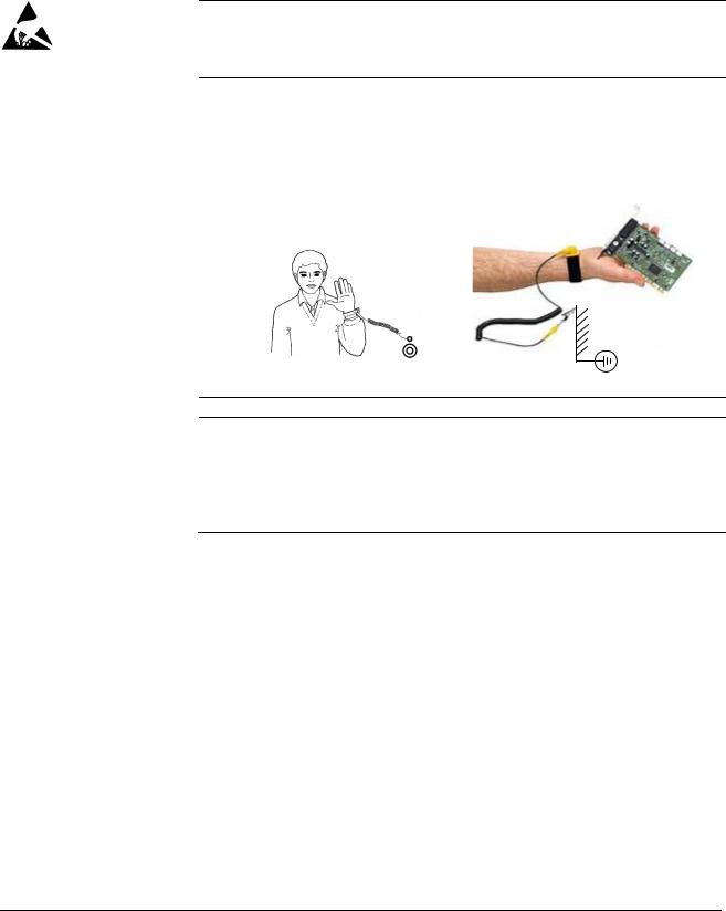
8
Printed circuit boards and fiber optic cables
These instructions are intended for all who handle the circuit boards and fiber optic cables. Ignoring the following instructions can cause damage to the equipment.
WARNING! The printed circuit boards contain components sensitive to electrostatic discharge. Wear a grounding wrist band when handling the boards. Do not touch the boards unnecessarily.
Use grounding strip:
ABB order no.: 3ADV050035P0001
WARNING! Handle the fiber optic cables with care. When unplugging optic cables, always grab the connector, not the cable itself. Do not touch the ends of the fibers with bare hands as the fiber is extremely sensitive to dirt. The minimum allowed bend radius is 35 mm (1.38 in.).
Safety instructions
3ADW000195R0501 DCS800 Service Manual e e

9
Mechanical installation
These notes are intended for all who install the drive. Handle the unit carefully to avoid damage and injury.
WARNING!
•DCS800 sizes D4 … D7: The drive is heavy. Do not lift it alone. Do not lift the unit by the front cover. Place units D4 and D5 only on its back.
DCS800 sizes D5 … D7: The drive is heavy. Lift the drive by the lifting lugs only. Do not tilt the unit. The unit will overturn from a tilt of about 6 degrees.
•Make sure that dust from drilling does not enter the drive when installing. Electrically conductive dust inside the unit may cause damage or lead to malfunction.
•Ensure sufficient cooling.
•Do not fasten the drive by riveting or welding.
Safety instructions
3ADW000195R0501 DCS800 Service Manual e e 3ADW000195R0101 DCS800 Service Manual e a

10
Operation
These warnings are intended for all who plan the operation of the drive or operate the drive. Ignoring the instructions can cause physical injury or death and/or damage to the equipment.
WARNING!
•Before adjusting the drive and putting it into service, make sure that the motor and all driven equipment are suitable for operation throughout the speed range provided by the drive. The drive can be adjusted to operate the motor at speeds above and below the base speed.
•Do not control the motor with the disconnecting device
(disconnecting mains); instead, use the control panel keys  and
and  , or commands via the I/O board of the drive.
•Mains connection
You can use a disconnect switch (with fuses) to disconnect the electrical components of the drive from the mains for installation and maintenance work. The type of disconnect switch used must be as per EN 60947-3, Class B, so as to comply with EU regulations, or a circuit-breaker type which switches off the load circuit by means of an auxiliary contact causing the breaker’s main contacts to open. The mains disconnect must be locked in its «OPEN» position during any installation and maintenance work.
•EMERGENCY STOP buttons must be installed at each control desk and at all other control panels requiring an emergency stop function. Pressing the STOP button on the control panel of the drive will neither cause an emergency stop of the motor, nor will the drive be disconnected from any dangerous potential.
To avoid unintentional operating states, or to shut the unit down in case of any imminent danger according to the standards in the safety instructions it is not sufficient to merely shut down the drive via signals «RUN», «drive OFF» or «Emergency Stop» respectively «control panel» or «PC tool».
•Intended use
The operating instructions cannot take into consideration every possible case of configuration, operation or maintenance. Thus, they mainly give such advice only, which is required by qualified personnel for normal operation of the machines and devices in industrial installations.
If in special cases the electrical machines and devices are intended for use in non-industrial installations — which may require stricter safety regulations (e.g. protection against contact by children or similar) — these additional safety measures for the installation must be provided by the customer during assembly.
Safety instructions
3ADW000195R0501 DCS800 Service Manual e e
![]()
11
Note:
•When the control location is not set to Local (L not shown in the status row of the display), the stop key on the control panel will not
stop the drive. To stop the drive using the control panel, press the LOC/REM key and then the stop key  .
.
Safety instructions
3ADW000195R0501 DCS800 Service Manual e e 3ADW000195R0101 DCS800 Service Manual e a

3ADW000195R0501 DCS800 Service Manual e e

|
13 |
|
Table of contents |
|
|
Safety instructions |
5 |
|
What this chapter contains……………………………………………………………………………………………. |
5 |
|
To which products this chapter applies…………………………………………………………………………… |
5 |
|
Usage of warnings and notes ……………………………………………………………………………………….. |
5 |
|
Installation and maintenance work…………………………………………………………………………………. |
6 |
|
Grounding………………………………………………………………………………………………………… |
7 |
|
Mechanical installation…………………………………………………………………………………………………. |
9 |
|
Operation …………………………………………………………………………………………………………………. |
10 |
|
Table of contents |
13 |
|
Introduction |
16 |
|
How to use this manual………………………………………………………………………………………………. |
16 |
|
Contents of this manual ……………………………………………………………………………………………… |
16 |
|
Target group …………………………………………………………………………………………………………….. |
16 |
|
Associated publications ……………………………………………………………………………………………… |
16 |
|
Storage and transport ………………………………………………………………………………………………… |
17 |
|
Name plate and type code ………………………………………………………………………………………….. |
17 |
|
Type code ………………………………………………………………………………………………………………… |
18 |
|
Current and voltage ratings…………………………………………………………………………………………. |
19 |
|
Fault Tracing Thyristors |
21 |
|
Tools ……………………………………………………………………………………………………………………….. |
21 |
|
For commissioning and fault tracing…………………………………………………………………… |
21 |
|
Additionally for service and preventive maintenance ……………………………………………. |
22 |
|
How to detect a faulty thyristor…………………………………………………………………………………….. |
22 |
|
A fuse is blown ……………………………………………………………………………………………….. |
22 |
|
DC-current pulses measured by an oscilloscope …………………………………………………. |
23 |
|
Thyristor diagnosis ………………………………………………………………………………………….. |
23 |
|
Ripple monitor ………………………………………………………………………………………………… |
23 |
|
How to find a faulty thyristor………………………………………………………………………………………… |
24 |
|
Converters size D1 to D4 (20…1000 A)………………………………………………………………. |
24 |
|
Blown fuses ……………………………………………………………………………………………………. |
24 |
|
Converters size D5, D6, and D7 (900…5200 A) …………………………………………………… |
25 |
|
Blown fuses ……………………………………………………………………………………………………. |
25 |
|
Ripple monitor ………………………………………………………………………………………………… |
25 |
|
Handling the Semiconductors |
27 |
|
General Instruction how to handle the Semiconductors ………………………………………………….. |
27 |
|
Exchange of Thyristors for Size D1 to D4 |
29 |
|
Installation of OnBoard bridge and thyristor modules in converters size D1 to D4 |
|
|
(20…1000 A) …………………………………………………………………………………………………………….. |
29 |
|
Required Tools ……………………………………………………………………………………………….. |
29 |
|
Find faulty thyristor modules …………………………………………………………………………….. |
29 |
|
Remove faulty thyristor modules ……………………………………………………………………….. |
30 |
|
Install new thyristor modules …………………………………………………………………………….. |
34 |
|
Table of contents |
3ADW000195R0501 DCS800 Service Manual e e

|
14 |
||
|
Remove faulty OnBoard bridge (V1) …………………………………………………………………. |
36 |
|
|
Install new OnBoard bridge (V1) ………………………………………………………………………. |
36 |
|
|
OnBoard bridge (V1) and thyristor module location in DCS800-S01 (2-Q) units |
………. 37 |
|
|
OnBoard bridge (V1) and thyristor module location in DCS800-S02 (4-Q) units………. |
38 |
|
|
OnBoard bridge and thyristor module terminals ………………………………………………….. |
39 |
|
|
Exchange of Thyristors for Size D5 |
41 |
|
|
Installation of «Disc Type» thyristor in converters size D5 (900… |
2000 A) ………………………….. |
41 |
|
Required Tools ………………………………………………………………………………………………. |
41 |
|
|
Disk type thyristors …………………………………………………………………………………………. |
42 |
|
|
Find faulty thyristor …………………………………………………………………………………………. |
45 |
|
|
Remove faulty thyristor……………………………………………………………………………………. |
46 |
|
|
Install new thyristor…………………………………………………………………………………………. |
47 |
|
|
Exchange of Thyristors for Size D6 |
51 |
|
|
Installation of «Disc Type» thyristor in converters size D6 (1900… |
3000 A) ………………………… |
51 |
|
Required Tools ………………………………………………………………………………………………. |
51 |
|
|
Disk type thyristors …………………………………………………………………………………………. |
52 |
|
|
BCT thyristors………………………………………………………………………………………………… |
53 |
|
|
Find faulty thyristor …………………………………………………………………………………………. |
54 |
|
|
Remove faulty thyristor……………………………………………………………………………………. |
55 |
|
|
Install new thyristor…………………………………………………………………………………………. |
58 |
|
|
Exchange of Thyristors for Size D7 |
65 |
|
|
Installation of «Disc Type» thyristor in converters size D7 (2050… |
5200 A) ………………………… |
65 |
|
Required Tools ………………………………………………………………………………………………. |
65 |
|
|
Find faulty thyristor …………………………………………………………………………………………. |
66 |
|
|
Install new thyristor…………………………………………………………………………………………. |
69 |
|
|
Exchange of SDCS-CON-4 |
75 |
|
|
General …………………………………………………………………………………………………………………… |
75 |
|
|
Required Tools ………………………………………………………………………………………………. |
75 |
|
|
Overview SDCS-CON-4 exchange……………………………………………………………………. |
75 |
|
|
Service |
83 |
|
|
How to remove the converter fans in frames D1 to D3 (two fans) ……………………………………. |
83 |
|
|
How to remove the converter fans in a frame D3 (four fans) …………………………………………… |
87 |
|
|
How to remove the converter fan in a frame D6 ……………………………………………………………. |
92 |
|
|
How to remove the converter fan in a frame D7 ……………………………………………………………. |
93 |
|
|
DCS800 firmware download ………………………………………………………………………………………. |
94 |
|
|
General…………………………………………………………………………………………………………. |
94 |
|
|
Download SDCS-CON-4 firmware…………………………………………………………………….. |
94 |
|
|
Add firmware or text files ……………………………………………………………………………….. |
107 |
|
|
Create a workspace………………………………………………………………………………………. |
114 |
|
|
Download SDCS-COM-8 firmware ………………………………………………………………….. |
129 |
|
|
Set type code …………………………………………………………………………………………………………. |
131 |
|
|
Type code table ……………………………………………………………………………………………. |
133 |
|
|
DC-Motor neutral zone adjustment ……………………………………………………………………………. |
134 |
|
|
Types concerned ………………………………………………………………………………………….. |
134 |
|
|
Summary …………………………………………………………………………………………………….. |
134 |
|
|
General……………………………………………………………………………………………………….. |
134 |
Table of contents
3ADW000195R0501 DCS800 Service Manual e e

|
15 |
|
|
Preventive Maintenance |
135 |
|
Recommended regular maintenance |
…………………………………………………………………………..136 |
|
Maintenance schedule ……………………………………………………………………………………………… |
136 |
|
Annual preventive maintenance…………………………………………………………………………………. |
137 |
|
3 years preventive maintenance ………………………………………………………………………………… |
140 |
|
6 years preventive maintenance ………………………………………………………………………………… |
141 |
|
9 years preventive maintenance ………………………………………………………………………………… |
143 |
|
Appendix A — Spare Parts List |
145 |
Table of contents
3ADW000195R0501 DCS800 Service Manual e e

16
Introduction
How to use this manual
The purpose of this service manual is to provide detailed information on how to service power converters from the DCS800 series.
Contents of this manual
Safety instructions
This chapter is located at the beginning of this manual.
Introduction
This chapter informs about the contents and the use of this manual as well as the boundary conditions applying and the thyristor power converter rating plate.
Fault Tracing Thyristors
This chapter describes how to detect and select a faulty thyristor.
Handling the Semiconductors
This chapter describes the handling of thyristors and thyristor modules.
Exchange of Thyristors of Sizes D1 to D4
This chapter describes the exchange of thyristors in converters sizes D1 to D4.
Exchange of Thyristors of Size D5
This chapter describes the exchange of thyristors in converters size D5.
Exchange of Thyristors of Size D6
This chapter describes the exchange of thyristors in converters size D6.
Exchange of Thyristors of Size D7
This chapter describes the exchange of thyristors in converters size D7
Exchange of SDCS-CON-4
This chapter describes the exchange of a SDCS-CON-4
Service
This chapter contains hardware information and technical hints.
Preventive Maintenance
This chapter describes the measures for preventive maintenance of the thyristor converters.
Appendix A Spare Parts list
The Appendix A contains the spare parts list of the converters.
Target group
This manual is designed to help those responsible for planning, installing, starting up and servicing the thyristor power converter.
These people should possess:
basic knowledge of physics and electrical engineering, electrical wiring principles, components and symbols used in electrical engineering, and
basic experience with DC drives and products.
Associated publications
A list of associated publications is published on the inner page of this manual’s cover, see DCS800 Drive Manuals. Here is a list of the most important ones:
The DCS800 Hardware Manual (3ADW000194) describes all hardware
Introduction
3ADW000195R0501 DCS800 Service Manual e e

17
components of the DCS800, their connections and settings (e.g. jumpers)
The DCS800 Firmware Description (3ADW000193) gives an overview of the
DCS800 firmware, describes all parameters, describes the function of the DCS Control Panel, gives support in case of faults and alarms and gives information about communication.
The above listed documentation can be found on the CD-ROM being attached to the DCS800 Quick Guide (3ADW000191).
Storage and transport
If the unit has been in storage prior to installation or is transported to another location, care must be taken to ensure that the environmental conditions are complied with (see Hardware Manual).
Name plate and type code
For purposes of identification, each thyristor power converter is fitted with name plates, stating the type code and the serial number, which serve for each unit’s individual identification.
The type code contains information about the characteristics and the configuration of the unit.
|
ABB Automation Products |
U1 |
3 525 V |
U2 |
610 V |
|||||||
|
20 A |
Made in Germany |
||||||||||
|
Type: DCS800-S02-0025-05 |
I1 |
I2 |
25 A |
||||||||
|
+K454 |
|||||||||||
|
Ser No: 0025421A06294264 |
f1 |
50/60 Hz |
If |
6 A |
+J409 |
||||||
|
SCCR |
65 kA |
Fan |
—- |
||||||||
|
Production year |
Rated input voltage |
Rated output current |
|
|
2006 and week 29 |
Rated input current |
Rated internal field |
exciter current Rated fan voltage
Plus code
Example of a name plate
Introduction
3ADW000195R0501 DCS800 Service Manual e e

18
Type code
The type code contains information on the specifications and configuration of the drive. The first digits from left express the basic configuration (e.g. DCS800-S01- 2005). The optional selections are given thereafter, on the name plate by plus code. The main selections are described below. Not all selections are available for all types.
|
Type code |
D C S 8 0 |
0 — A A X — Y Y |
Y Y — Z Z |
— plus code |
||||||||||
|
Position |
A X |
Y |
Z |
B |
||||||||||
|
Position |
Plus code |
|||||||||||||
|
Product series |
DCS800 |
|||||||||||||
|
A |
Type |
S0 = Standard converter module IP00 |
||||||||||||
|
R0 = Rebuild system |
||||||||||||||
|
E0 = Panel solution |
||||||||||||||
|
A0 = Enclosed converter |
||||||||||||||
|
X |
Bridge type |
1 = Single bridge (2-Q) |
||||||||||||
|
2 = 2 anti parallel bridges (4-Q) |
||||||||||||||
|
Y |
Rated DC current |
YYYY = Rated current (e.g. 0025 = 25 ADC) |
||||||||||||
|
ZZ |
Rated AC voltage |
04 = 400 VAC |
||||||||||||
|
05 = 525 VAC |
||||||||||||||
|
06 = 600 VAC |
||||||||||||||
|
07 = 690 VAC |
||||||||||||||
|
08 = 800 VAC |
||||||||||||||
|
10 = 990 VAC |
||||||||||||||
|
12 = 1200 VAC |
||||||||||||||
|
B |
Power connection |
— = Standard D1 … D6 |
||||||||||||
|
L = Left side D7 |
||||||||||||||
|
R = Right side D7 |
||||||||||||||
|
a = Second thyristor type D5, D6 |
||||||||||||||
|
Internal field exciter |
+S164 |
With internal field exciter, external supply (only D5:25 A, Rebuild kit: 25 A/16 A) |
||||||||||||
|
configuration |
+0S163 |
Without internal field exciter (only D1 … D4) |
||||||||||||
|
Fan voltage |
Size D4 |
|||||||||||||
|
Standard fan voltage: |
230 V / 1-ph |
|||||||||||||
|
+S171 |
Additional fan voltage: |
115 V / 1-ph |
||||||||||||
|
Size D6 |
||||||||||||||
|
Standard fan voltage for 400 V / 500 V / 800 V units: |
400-500 V / 3-ph |
|||||||||||||
|
Standard fan voltage for 600 V / 690 V units: |
525-690 V / 3-ph |
|||||||||||||
|
+S172 |
Additional fan voltage for 600-690 V units: |
400-500 V / 3-ph |
||||||||||||
|
Current measurement |
+S175 |
SDCS-CMA-2 for sizes D5 to D7 |
||||||||||||
|
Voltage measurement |
+S186 |
120 V SDCS-SUB-4 for sizes D1 … D4 |
||||||||||||
|
+S180 |
600 V for sizes D6 and D7 |
|||||||||||||
|
+S181 |
690 V for sizes D6 and D7 |
|||||||||||||
|
+S182 |
800 V for sizes D6 and D7. |
|||||||||||||
|
+S183 |
990 V for sizes D6 and D7. |
|||||||||||||
|
+S189 |
Galvanic isolation for sizes D6 and D7 |
|||||||||||||
|
SDCS-DSL-4 |
+S199 |
With SDCS-DSL-4 |
||||||||||||
|
+0S199 |
Without SDCS-DSL-4 |
|||||||||||||
|
+ plug-in options |
||||||||||||||
|
DCS Control Panel |
0J400 |
Without DCS Control Panel |
||||||||||||
|
J409 |
Door mounting Kit (cable length 3 m) |
|||||||||||||
|
Fieldbus |
K454 |
Profibus RPBA |
||||||||||||
|
K451 |
DeviceNet RDNA |
|||||||||||||
|
K466 |
Ethernet IP + Modbus TCP RETA |
|||||||||||||
|
K458 |
Modbus RMBA |
|||||||||||||
|
I/O and DDCS |
L500 |
Analogue Extension RAIO |
||||||||||||
|
L501 |
Digital Extension RDIO |
|||||||||||||
|
L508 |
DDCS Communication board (10 Mbaud CH0) SDCS-COM-81 |
|||||||||||||
|
L509 |
DDCS Communication board (5 Mbaud CH0) SDCS-COM-82 |
Introduction
3ADW000195R0501 DCS800 Service Manual e e

19
The technical data and specifications are valid as of going to press. ABB reserves the right to make subsequent alterations.
If you have any questions concerning your drive system, please contact your local ABB agent.
Current and voltage ratings
|
Unit size |
2-Q rated current |
4-Q rated current |
Supply voltage [VAC] |
||||||
|
DCS800-01 [ADC] |
DCS800-02 [ADC] |
||||||||
|
400 |
525 |
600 |
690 |
800 |
990 |
1200 |
|||
|
D1 |
20 |
25 |
X |
X |
|||||
|
45 |
50 |
X |
X |
||||||
|
65 |
75 |
X |
X |
||||||
|
90 |
100 |
X |
X |
||||||
|
125 |
140 |
X |
X |
||||||
|
D2 |
180 |
200 |
X |
X |
|||||
|
230 |
260 |
X |
X |
||||||
|
D3 |
315 |
350 |
X |
X |
X |
||||
|
405 |
450 |
X |
X |
||||||
|
470 |
520 |
X |
X |
||||||
|
D4 |
610 |
680 |
X |
X |
X |
||||
|
740 |
820 |
X |
X |
||||||
|
900 |
1000 |
X |
X |
||||||
|
D5 |
900 |
900 |
X |
X |
|||||
|
1200 |
1200 |
X |
X |
||||||
|
1500 |
1500 |
X |
X |
X |
X |
||||
|
2000 |
2000 |
X |
X |
X1 |
X1 |
||||
|
D6 |
1900 |
1900 |
X |
||||||
|
2050 |
2050 |
X |
X |
X |
|||||
|
2500 |
2500 |
X |
X |
X |
X |
X |
|||
|
3000 |
3000 |
X |
X |
X |
X |
X |
|||
|
D7 |
2050 |
2050 |
X |
||||||
|
2600 |
2600 |
X |
X |
||||||
|
3300 |
3300 |
X |
X |
X |
X |
X |
X |
X |
|
|
4000 |
4000 |
X |
X |
X |
X |
X |
X |
X |
|
|
4800 |
4800 |
X |
X |
X |
|||||
|
5200 |
5200 |
X |
X |
1 only available as 2-Q drive
Introduction
3ADW000195R0501 DCS800 Service Manual e e

3ADW000195R0501 DCS800 Service Manual e e
![]()
21
Fault Tracing Thyristors
Tools
For commissioning and fault tracing
Following software tools are mandatory:
DriveWindow Light including commissioning wizard and DWL AP for Adaptive Program and
DriveWindow for fast drive monitoring using SDCS-COM-8.
Following tools are mandatory in addition to standard tools:
An oscilloscope including memory function with either galvanically isolating transformer or isolating amplifier (probe) for safe measurements. It can also be a hand held (portable) oscilloscope.
A clamp on current probe. In case the scaling of the DC load current needs to be checked it must be a DC clamp on current probe.
A voltmeter (at least CAT III 1000 V):
1000 V probes and test leads:
An ESD-field service kit (ABB Service Finland code 0001ESD / MS-Antistatic):
Make sure that all equipment in use is suitable for the voltage level applied to the power part!
Fault Tracing Thyristors
3ADW0000195R0501DCS8000ServiceManualeeee

22
Additionally for service and preventive maintenance
Following additional tools are mandatory for cleaning:
An ESD safe blower / ESD vacuum cleaner (ABB Service Finland code 0006ESD / MUNTZ 555-ESD-S-E):
How to detect a faulty thyristor
Thyristor problems can be noticed differently:
A fuse is blown
This is an indication, that a strong overcurrent has happened due to one of the following reasons:
An internal short circuit between the phases (line side) because of a defective thyristor (short circuit inside a thyristor from anode to cathode).
An internal short circuit between the phases (line side) because of circulating current in a 4-Q converter (malfunction of the control electronics, no thyristor defective).
An external short circuit at the DC terminals of the converter without sufficient impedance.
A commutation fault during generating (active braking with high current, high EMF and with low AC voltage) of a 4-Q converter.
Note:
In case of parallel fuses: If one of the parallel fuses is blown, all parallel fuses have to be changed. The ‘undamaged’ fuses might be ‘half-blown’ and will blow with the next high current.
Fault Tracing Thyristors
3ADW000195R0501 DCS800 Service Manual e e

23
DC-current pulses measured by an oscilloscope
Connect an oscilloscope to the fixed AO I-act (X4:9/10 on the SDCS-CON-4 or X4:5/6 on the SDCS-IOB-3) and check for the proper amount of current pulses:
Six current pulses in positive direction
There should be six current pulses in positive direction.
In case of a 4-Q converter also the six current pulses for the negative direction have to be checked.
Thyristor diagnosis
Also the thyristor diagnosis provided by the firmware can be used:
Switch the drive to local mode (DriveWindow, DriveWindow Light, DCS Control Panel or local I/O).
Start the thyristor diagnosis by means of ServiceMode (99.06) = ThyDiagnosis and set On and Run within 20 s.
During the thyristor diagnosis the main contactor will be closed and the thyristors are checked. The field current is not released while the thyristor diagnosis is active and thus the motor should not turn.
When the thyristor diagnosis is finished check Diagnosis (9.11) for details.
Ripple monitor
The ripple monitor indicates that the ripple of the DC current is much higher than normal. In such a case, most often one thyristor does not work. It’s missing current contribution causes a deep dip in the direct current.
The structure of the current loop (current controller) will force the other thyristors to compensate the dip by a certain overcurrent in order to keep the average current constant. Such a compensation results in a ripple monitoring fault during motoring mode operation with 90°.
The reason for a current less thyristor may be:
Fault Tracing Thyristors

24
A fuse has disconnected one of the six thyristors. This is possible only for converters with 900 … 5200 A (six internal branch fuses). A converter with three external fuses stops working completely at once when one of the three AC input fuses interrupts a phase input of the converter.
A thyristor does not get firing pulses or does not react to firing pulses.
The current controller may be totally mismatched to the DC load.
The AC mains network is causing that fault message. In this case, asymmetrical phase shift, uneven phase voltage or critical designed power factor correction equipment or harmonic reduction equipment can be the reason.
How to find a faulty thyristor
If a blown fuse is suspected in the converter, the problem is caused most often by a faulty thyristor. To make sure, that a thyristor is the reason and needs to be exchanged fault tracing must be done in two different ways, depending on the size of the converter.
In general, make sure, that all safety instructions, given within this manual or within the safety instructions, related to the machine or the application itself, are obeyed.
Converters size D1 to D4 (20…1000 A)
These converters require semiconductor fuses in the 3 AC lines.
The converter must be disconnected from the mains.
One motor armature cable should be disconnected from the converter.
Blown fuses
Using the OHM function of a normal multimeter, measurements must be made from each AC terminal to each DC terminal (U1 to C1, V1 to C1, W1 to C1, U1 to D1, V1 to D1 and W1 to D1; see picture Anti-parallel B6-bridges with
branching fuses on page 45). Normally, every measurement should show high resistance (> 1 k ).
Target: find a short circuit, indicated by low resistance ( <1 ) (destroyed thyristor).
If the converter is designed with half-bridge thyristor modules, then a module consists of two anti-parallel thyristors. In this case it is sufficient to know which thyristor pair or module has a defective thyristor because the complete module must be replaced.
After a thyristor module is replaced, the above mentioned measurement should be done another time to make sure that all faulty thyristors have been detected!
Note:
The RC circuit could also cause 0 result for a short time.
The measurement, showing less resistance than 1 should be made a second time with test leads applied to the terminals with opposite polarity; if this measurement shows the same result, one or two thyristors located in that path are faulty; they need to be replaced.
Fault Tracing Thyristors
3ADW000195R0501 DCS800 Service Manual e e

25
Converters size D5, D6, and D7 (900…5200 A)
These converters are equipped with fuses in the branches of the power part.
The converter must be disconnected from the mains.
Blown fuses
In case of a blown fuse, the faulty thyristor or the faulty pair of thyristors are already isolated at one side from the others and therefore the faulty branch is known (see picture Anti-parallel B6-bridges with branching fuses on page 45).
The OHM test should be performed, when the thyristor is still clamped. Outside the converter a special thyristor clamping device is needed.
For 4-Q converters with anti-parallel thyristors or BCT’s:
The selection of a forward or reverse thyristor or BCT (Bidirectional-Controlled-Thyristor) is done during the disassembly. Continue with related part Exchange of Thyristors for Size D5, D6 or D7 section Find faulty thyristor.
After a thyristor was replaced, the OHM test should be done another time to make sure that all faulty thyristors have been detected! If the motor is still connected to the converter the result of the measurement may be wrong.
Ripple monitor
If the ripple monitor fault occurred, a fault tracing as described above must be carried out:
Check the fuses and the thyristors, according to the statements before.
If the power section seems to be ok, but still one or more thyristors don’t take current, something went wrong in between the firing pulse generation and the thyristor’s gate; in this case check:
Is a firing pulse present on the primary side of the firing pulse transformer?
Is a firing pulse present on the secondary side of the firing pulse transformer?
Is the firing pulse transferred to the gate of the thyristor? Are there all electrical connections still healthy?
Can the thyristor be fired with the applied firing pulse? Is the pulse form of the firing pulse identical at all measuring positions?
Check the settings of the current controller.
Check the AC mains network by taking recordings of the line voltage and current at all 3 phases at the same time.
Fault Tracing Thyristors

26
Fault Tracing Thyristors
3ADW000195R0501 DCS800 Service Manual e e

27
Handling the Semiconductors
General Instruction how to handle the Semiconductors
Thyristor modules, busbars and fuses have to be mounted with the correct torque using a torque screw driver or torque wrench.
In converters sizes D5 (900 … 2000 A), D6 (1900 … 3000 A) and D7 (2050 … 5200 A) the mounting force is indicated by an indicating spring welded to the mounting clamp, which is inside the unit.
Always mark suspected damaged components clearly after removing them from the circuit, to avoid confusion with «good» components.
When removing a damaged semiconductor, write down how and where it was installed (direction, location, connected gate leads and with BCT’s the position of the gate connectors).
Check that the new and old components have the same type designation or that the new component can replace the old one. A semiconductor can be replaced by different compatible semiconductor according to the codes in the manufacturers’ table.
Semiconductor components are high-precision products. All unnecessary used tools and objects might damage the easily dented and scratched surfaces of the semiconductors.
1.Keep new semiconductors as long as possible in their original packages.
2.Use protective gloves if possible.
3.Clean work area and hands frequently.
4.Use good illumination.
Handling the Semiconductors
3ADW000195R0501 DCS800 Service Manual e e

28
Handling the Semiconductors
3ADW000195R0501 DCS800 Service Manual e e

29
Exchange of Thyristors for Size D1 to D4
Installation of OnBoard bridge and thyristor modules in converters size
D1 to D4 (20…1000 A)
All DCS800 size D1 to D4 are equipped with an OnBoard bridge (excitation) and thyristor modules. In order to keep the operating temperature of the semiconductor module low, the joint between the heat sink and the module should have a good heat conducting ability. The electrical conductivity of the connectors must also be good. For this reason the following instructions must be observed with particular care.
Required Tools
Special tools or material needed in addition to standard tools for the exchange of thyristor modules:
|
Torx screwdrivers: |
TX10, TX20, TX25 |
|
|
Torque spanner: |
mounting torques for the OnBoard bridge and the |
|
|
thyristor modules to heat sink and electrical |
||
|
connections see table Nominal mounting torque for |
||
|
OnBoard bridge and thyristor modules on page 35 |
Screws are metric type; use appropriate nuts
Tissue paper
Solvent (e.g. ethanol)
Thermal joint compound: type Berulub FZ1 E3
|
(grease) |
|
|
Manufacturer: |
Carl Bechem GmbH, 58089 Hagen |
|
ABB Service: |
GHSN 390 011 P 0051 |
|
or |
|
|
thermal joint compound: |
type WLPF 20 (10 ml) |
|
ABB Service: |
GHSN 390 011 P 10 |
Before the work is started, disconnect the converter from the power supply completely, then check the voltage free condition and make sure, everything is located in an electrical and mechanical safe condition!
Find faulty thyristor modules
See Fault Tracing Thyristors of this publication.
Exchange of Thyristors for Size D1 to D4
3ADW000195R0501 DCS800 Service Manual e e

30
Remove faulty thyristor modules
1. Remove the DCS Control Panel and design cover:
 Remove DCS Control Panel
Depress the locks by means of a screwdriver to remove the design cover
Remove design cover
2.Remove all plug in options on the intermediate cover e.g.:
serial communication modules (R-type),
extension I/O modules (RAIO, RDIO),
extension modules for second encoder (RTAC) or resolver (RRIA),
communication board (SDCS-COM-8),
isolated I/O (SDCS-IOB-2x, SDCS-IOB-3) and
SDCS-MEM-8 (Memory Card).
3.Remove the intermediate cover by depressing the two locks on the upper right and left hand side of the cover:
Depress the locks to remove the design cover
Remove all options, so that the intermediate cover is empty
Remove plug in options
Exchange of Thyristors for Size D1 to D4
3ADW000195R0501 DCS800 Service Manual e e
![]()
31
4.Disconnect all I/O plugs (X3 to X7) at the SDCS-CON-4 and the plugs at the SDCS-DSL-4 board, if used (X51 to X54):
Disconnect all plugs from SDCS-
CON-4 and SDCS-DSL-4 boards
Disconnect all plugs
5. Remove the grounding plug and the holding screw at the electronic tray:
Remove the grounding plug and the holding screw
Remove grounding and screws
Exchange of Thyristors for Size D1 to D4
3ADW000195R0501 DCS800 Service Manual e e

32
6.To unhinge the electronic tray including the SDCS-CON-4 pull it up and then out. Before remove tray completely unplug the flat cables (X12, X13, X37):
Electronic tray with SDCS-CON-4
Remove flat cables
Unhinge electronic tray
7. Remove all cables and plugs at the SDCS-PIN-4:
Keep winding direction and amount of windings for T100 in mind.
T100
Remove all cables and plugs
How to handle X8:
X8
use screw driver
Remove cables at the SDCS-PIN-4
Attention:
Write down the winding direction of the cable through T100!
D1: thread the wire 4 times through the hole in T100 (that equals 3 loops)
D2 — D4: thread the wire 1 time through the hole in T100 (that equals no loops)
Exchange of Thyristors for Size D1 to D4
3ADW000195R0501 DCS800 Service Manual e e

33
8. Remove the SDCS-PIN-4 board:
|
OnBoard field exciter |
Snubber resistor |
||||||
|
bridge module |
|||||||
|
Thyristor modules |
|||||||
|
Current transformer |
Temperature sensor |
|
Remove SDCS-PIN-4
9.Remove the gate leads from the faulty thyristor module and mark the connectors clearly.
10.Remove the busbars necessary to get full access to the faulty thyristor module.
11.If a current transformer must be removed, mark its position and the connections clearly.
Note:
Remove only as many parts as needed around the faulty thyristor module.
12.Remove the faulty thyristor module and mark it clearly as defective.
Exchange of Thyristors for Size D1 to D4
3ADW000195R0501 DCS800 Service Manual e e

34
Install new thyristor modules
1.Ensure that the new thyristor module is of the correct type (see appendix A of this manual).
2.Remove old heat conducting compound (grease) from the heat sink. Clean the mounting surfaces (heat sink and thyristor module) with an appropriate solvent (e.g. ethanol) by means of tissue paper. When the heat sink is clean, spread out the heat conducting compound with a rubber spatula or by hand.
3.Apply a thin layer of heat conducting compound to the new thyristor module:
Application of heat conducting compound
4.Spread the heat conducting compound evenly by moving the thyristor module forward and backward on the heat sink.
5.Tighten all clamping screws by hand until the screw heads touch the bottom of the thyristor module. Then tighten the screws to 2.0 Nm torque.
Note:
If the thyristor module is mounted by means of four screws, tighten the screws crosswise.
6.Tighten the screws to nominal torque according to table Nominal mounting torque for OnBoard bridge and thyristor modules page 35.
Exchange of Thyristors for Size D1 to D4
3ADW000195R0501 DCS800 Service Manual e e

35
|
OnBoard bridge and thyristor modules |
Nominal mounting torque |
|||
|
Size |
Type |
Electrical |
Thyristor module |
|
|
connections |
to heat sink |
|||
|
29 mm bridge block |
VVZF 70-16 |
— |
5 Nm |
|
|
20 mm block |
SKKT 27, 42, 57, 106 |
3 Nm |
5 Nm |
|
|
20 mm block |
MCC 26, 44, 56, 95 |
2.5 … 4 Nm |
2.5 … 4 Nm |
|
|
34 mm block |
MCC 162 |
4.45 … 5.5 Nm |
2.25 … 2.75 Nm |
|
|
34 mm block |
SKKT 162 |
5 Nm |
5 Nm |
|
|
34 mm block |
TT 162 |
6 Nm |
6 Nm |
|
|
50 mm block |
MCC 255 |
11 … 13 Nm |
4.5 … 7 Nm |
|
|
50 mm block |
TT 250, 330 |
12 Nm |
6 Nm |
|
|
60 mm block |
TT 425, 570 |
12 Nm |
6 Nm |
|
Nominal mounting torque for OnBoard bridge and thyristor modules
7.Reinstall the current transformer, make sure, its position is correct.
8.Reinstall the busbars, make sure, the correct torque is applied according to table Nominal mounting torque for OnBoard bridge and thyristor modules on page 35.
9.Reconnect all gate leads to the thyristor module.
10.Reinstall the SDCS-PIN-4 board.
11.Reconnect all cables and plugs at the SDCS-PIN-4:
snubber resistor (X30, X31),
temperature sensor (X22),
current transformers (X3, X4, X5),
OnBoard excitation (X8, X9, X11), use proper winding direction and amount of windings for T100
gate leads (first X16, X18 then X15, X17),
OnBoard excitation line voltage (X1, X2, X7),
all plugs (X10, X96, X99) and
all flat cables (X12, X13, X37), use the lock connectors at the SDCS-PIN-4
12.Reconnect the flat cables at the SDCS-CON-4 (X12, X13, X37) and re-hinge the electronic tray.
13.Reconnect the grounding plug and the holding screw at the electronic tray.
14.Reconnect all I/O plugs at the SDCS-CON-4 (X3 to X7) and the plugs at the SDCS-DSL-4 (X51 to X54).
15.Reinstall the intermediate cover, all plug in options and the design cover.
Exchange of Thyristors for Size D1 to D4
3ADW000195R0501 DCS800 Service Manual e e

36
Remove faulty OnBoard bridge (V1)
1.Follow the instructions Remove faulty thyristor modules until step 8 is done.
2.Remove all connectors from the faulty OnBoard bridge and mark the connectors clearly.
3.Remove the faulty OnBoard bridge and mark it clearly as defective.
Install new OnBoard bridge (V1)
1.Ensure that the new OnBoard bridge is of the correct type (see appendix A of this manual).
2.Remove old heat conducting compound (grease) from the heat sink. Clean the mounting surfaces (heat sink and OnBoard bridge) with an appropriate solvent (e.g. ethanol) by means of tissue paper. When the heat sink is clean, spread out the heat conducting compound with a rubber spatula or by hand.
3.Apply a thin layer of heat conducting compound to the new OnBoard bridge.
4.Spread the heat conducting compound evenly by moving the OnBoard bridge forward and backward on the heat sink.
5.Tighten all clamping screws by hand until the screw heads touch the bottom of the thyristor module. Then tighten the screws to 2.0 Nm torque.
6.Tighten the screws to nominal torque according to table Nominal mounting torque for OnBoard bridge and thyristor modules on page 35.
7.Reconnect all connectors to the OnBoard bridge.
8.Follow the instructions Install new thyristor modules beginning with step 10.
Exchange of Thyristors for Size D1 to D4
3ADW000195R0501 DCS800 Service Manual e e

37
OnBoard bridge (V1) and thyristor module location in DCS800-S01 (2-Q) units
DCS800-S01-0020 … 0180
V1
|
V14/V11 |
|
| <![if ! IE]>
<![endif]>K2 G2 |
<![if ! IE]>
<![endif]>K1 G1 |
|
V16/V13 |
|
| <![if ! IE]>
<![endif]>K2 G2 |
<![if ! IE]>
<![endif]>K1 G1 |
|
V12/V15 |
|
| <![if ! IE]>
<![endif]>K2 G2 |
<![if ! IE]>
<![endif]>K1 G1 |
|
V1 |
|
V14/V11 |
| <![if ! IE]>
<![endif]>K2 G2 G1 K1 |
| <![if ! IE]>
<![endif]>A |
| <![if ! IE]>
<![endif]>K |
| <![if ! IE]>
<![endif]>AK |
DCS800-S01-0315 … 0470
|
V16/V13 |
| <![if ! IE]>
<![endif]>K2 G2 G1 K1 |
| <![if ! IE]>
<![endif]>A |
| <![if ! IE]>
<![endif]>K |
| <![if ! IE]>
<![endif]>AK |
|
V12/V15 |
| <![if ! IE]>
<![endif]>K2 G2 G1 K1 |
| <![if ! IE]>
<![endif]>A |
| <![if ! IE]>
<![endif]>K |
| <![if ! IE]>
<![endif]>AK |
|
V1 |
|
V14/V11 |
| <![if ! IE]>
<![endif]>A |
| <![if ! IE]>
<![endif]>K |
| <![if ! IE]>
<![endif]>AK |
DCS800-S01-0610 … 0900
|
V16/V13 |
| <![if ! IE]>
<![endif]>A |
| <![if ! IE]>
<![endif]>K |
| <![if ! IE]>
<![endif]>AK |
|
V12/V15 |
| <![if ! IE]>
<![endif]>A |
| <![if ! IE]>
<![endif]>K |
| <![if ! IE]>
<![endif]>AK |
DCS800 loc of mod 1Q.dsf
Location of the OnBoard bridge and thyristor modules in DCS800-S01 (2-Q) units
Note:
This drawing is only showing the location of the OnBoard bridge and thyristor modules, the actual converter module size is different!
Exchange of Thyristors for Size D1 to D4
3ADW000195R0501 DCS800 Service Manual e e

38
OnBoard bridge (V1) and thyristor module location in DCS800-S02 (4-Q) units
DCS800-S02-0025 … 0200
V1
|
V11/V24 |
V13/V26 |
V15/V22 |
|||||||
|
DCS800-S02-0350 … 0520 |
|||||||||
|
V1 |
|||||||||
|
V11 |
K1 |
K2 |
V14 |
||||||
|
G1 |
A |
K |
AK |
AK |
K |
A |
G2 |
||
|
G2 |
G1 |
||||||||
|
V24 |
K2 |
K1 |
V21 |
||||||
|
V15 |
K1 |
K2 |
V12 |
||||||
|
G1 |
A |
K |
AK |
AK |
K |
A |
G2 |
||
|
V22 |
G2 |
G1 |
V25 |
||||||
|
K2 |
K1 |
||||||||
|
V13 |
K1 |
K2 |
V16 |
||||||
|
G1 |
A |
K |
AK |
AK |
K |
A |
G2 |
||
|
V26 |
G2 |
G1 |
V23 |
||||||
|
K2 |
K1 |
||||||||
DCS800-S02-0260
V1
| <![if ! IE]>
<![endif]>G1 K1 |
<![if ! IE]>
<![endif]>G2 K2 |
|
V11/V24 |
|
V14/V21 |
|
| <![if ! IE]>
<![endif]>K2 G2 |
<![if ! IE]>
<![endif]>K1 G1 |
| <![if ! IE]>
<![endif]>G1 K1 |
<![if ! IE]>
<![endif]>G2 K2 |
|
V13/V26 |
|
V16/V23 |
|
| <![if ! IE]>
<![endif]>K2 G2 |
<![if ! IE]>
<![endif]>K1 G1 |
| <![if ! IE]>
<![endif]>G1 K1 |
<![if ! IE]>
<![endif]>G2 K2 |
|
V15/V22 |
|
V12/V25 |
|
| <![if ! IE]>
<![endif]>K2 G2 |
<![if ! IE]>
<![endif]>K1 G1 |
DCS800-S01-0680 … 1000
|
V1 |
V26/V13 |
V22/V15 |
|
V24/V11 |
||
| <![if ! IE]>
<![endif]>A |
<![if ! IE]>
<![endif]>A |
<![if ! IE]>
<![endif]>A |
| <![if ! IE]>
<![endif]>K |
<![if ! IE]>
<![endif]>K |
<![if ! IE]>
<![endif]>K |
| <![if ! IE]>
<![endif]>AK |
<![if ! IE]>
<![endif]>AK |
<![if ! IE]>
<![endif]>AK |
| <![if ! IE]>
<![endif]>AK |
<![if ! IE]>
<![endif]>AK |
<![if ! IE]>
<![endif]>AK |
| <![if ! IE]>
<![endif]>K |
<![if ! IE]>
<![endif]>K |
<![if ! IE]>
<![endif]>K |
| <![if ! IE]>
<![endif]>A |
<![if ! IE]>
<![endif]>A |
<![if ! IE]>
<![endif]>A |
|
V21/V14 |
V23/V16 |
V25/V12 |
DCS800 loc of mod 4Q.dsf
Location of the OnBoard bridge and thyristor modules in DCS800-S02 (4-Q) units
Note:
This drawing is only showing the location of the OnBoard bridge and thyristor modules, the actual converter module size is different!
Exchange of Thyristors for Size D1 to D4
3ADW000195R0501 DCS800 Service Manual e e

39
OnBoard bridge and thyristor module terminals
The next figures show the terminals of the OnBoard bridge and all used thyristor modules. The terminal description is also stamped or marked by a sticker on the OnBoard bridge and all thyristor modules.
For all firing pulse cables is valid: Yellow is gate lead.
Red is cathode lead.
VVZF 70-16
|
(AK)(K) |
(A |
(AK)(K) |
(A |
||||
|
1 |
2 5 4 |
6 7 |
3 |
1 |
2 4 5 |
7 6 |
3 |
|
1 |
2 |
3 |
1 |
2 |
3 |
|
7 G |
6 G |
||||
|
6 K |
7 K |
||||
|
5 K |
4 K |
||||
|
4 G |
5 G |
||||
|
SKKT 27, 42, 57, 106 |
MCC26, 44, 56, 95 |
|
(AK) (K) |
(A) |
|||||
|
1 |
2 5 4 |
7 |
6 |
3 |
||
|
6 |
7 |
|||||
|
1 |
2 |
3 |
||||
|
6 |
7 |
|||||
|
5 |
4 |
4 |
5 |
|||
|
SKTT 162 |
||||||
|
MCC162 |
Exchange of Thyristors for Size D1 to D4
3ADW000195R0501 DCS800 Service Manual e e

40
|
AK |
K |
A |
||
|
K2 G2 |
||||
|
K1 G1 |
||||
|
TT 162 |
MCC255 |
|||
|
(A) |
(K) (AK) |
|||
|
AK K |
A 3 |
6G 7K |
5G 4K2 1 |
|
|
K1 G1 |
K2 |
G2 |
|
5G4K |
||||||
|
K2 |
3 |
1 |
||||
|
AK |
K |
A |
G2 |
2 |
||
|
G1 |
||||||
|
K1 |
||||||
|
6G7K |
Terminals of the OnBoard bridge and all thyristor modules
Exchange of Thyristors for Size D1 to D4
3ADW000195R0501 DCS800 Service Manual e e
![]()
TX10, TX20, TX25 13 Nm (M8)
25 Nm (M10)
50 Nm (M12)
41
Exchange of Thyristors for Size D5
Installation of «Disc Type» thyristor in converters size D5 (900…2000 A)
All DCS800 converters sizes D5/D6/D7 are equipped with disk type thyristors. The structure of the «Disc type» semiconductor component is such that it requires a certain compression force to operate. The prevention of overheating of the component essentially depends on a good heat dissipation between the semiconductor and the conducted heat sink. It is thus important that all joints have good thermal and electrical conduction.
Required Tools
Special tools or material needed in addition to standard tools for the exchange of thyristor modules:
Torx screwdrivers:
Torque spanner for electrical connections:
Screws are metric type; use appropriate nuts.
17 mm ring spanner for fuse and busbar connections.
17 mm ring spanner for press clamp.
Tissue paper / solvent (e.g. ethanol).
Thermal joint compound: type BECHEM-RHUS SU 2 (grease)
|
Manufacturer: |
Carl Bechem GmbH, 58089 Hagen |
|
ABB Service: |
GHSN 390 001 P 0001 |
|
Disassembly tool |
3ADT 621 023 P1 |
|
Note: |
For more detailed information about the wiring of the power part, see Hardware Manual.
Therefore strict observance of the build in instructions given below is of utmost importance. Make sure that the new component can replace the old one in accordance with the spare part list (see Appendix A).
Semiconductors and heat sinks are to be handled carefully to avoid scratches and other damage. Avoid touching the contact surfaces. Do not lift the semiconductor with the gate wire. Do not lift the semiconductor by touching the current contact surfaces. Do not damage the welding flange or the contact surface.
Before you start work, disconnect the converter completely from the power supply then check the voltage free condition and make sure, everything is located in an electrically and mechanically safe condition!
Exchange of Thyristors for Size D5
3ADW000195R0501 DCS800 Service Manual e e

42
Disk type thyristors
Some converter modules size D5 are equipped with different disc type thyristors. For easy identification the name plate of the converter module is marked with “a” after the voltage identification:
|
Converter with original |
U1 |
Converter with second |
|
thyristor type T459Nxxx |
thyristor type T460Nxxx |
|
|
Id code: DCA0012007P0001 |
Id code: 3ADC340105P0001 |
|
|
DCS800-S01-0900-06 |
3 ~ 600 VAC |
DCS800-S01-0900-06a |
|
DCS800-S02-0900-06 |
3 ~ 600 VAC |
DCS800-S02-0900-06a |
|
DCS800-S01-0900-07 |
3 ~ 690 VAC |
DCS800-S01-0900-07a |
|
DCS800-S02-0900-07 |
3 ~ 690 VAC |
DCS800-S02-0900-07a |
|
Converter with original |
U1 |
Converter with second |
|
thyristor type T589Nxxx |
thyristor type T590Nxxx |
|
|
Id code: DCA0012015P0001 |
Id code: 3ADC340106P0001 |
|
|
DCS800-S01-1200-04 |
3 ~ 400 VAC |
DCS800-S01-1200-04a |
|
DCS800-S02-1200-04 |
3 ~ 400 VAC |
DCS800-S02-1200-04a |
|
DCS800-S01-1200-05 |
3 ~ 525 VAC |
DCS800-S01-1200-05a |
|
DCS800-S02-1200-05 |
3 ~ 525 VAC |
DCS800-S02-1200-05a |
|
Parts list |
The current and voltage ratings of original and second thyristor type are the same, but the sizes of gate and cathode terminals are different. Thus it is not possible to interchange both thyristor types as spares.
Attention: Use always the correct spare thyristor!
Original thyristor type (900 A)
Converter with original thyristor type T459Nxxx Id code: DCA0012007P0001
Original thyristor type
Exchange of Thyristors for Size D5
3ADW000195R0501 DCS800 Service Manual e e

43
|
Gate (G): |
Faston 2.8 x 0.8 mm |
|
Cathode (HK): |
Faston 4.8 x 0.8 mm |
|
Conductive plate: |
Diameter 36 mm |
Second thyristor type (900 A)
Converter with second thyristor type T460Nxxx Id code: 3ADC340105P0001
|
Second thyristor type |
|
|
Gate (4): |
Round terminal D = 1.5 mm |
|
Cathode (5): |
Faston 4.8 x 0.5 mm |
|
Conductive plate: |
Diameter 36 mm |
Original thyristor type (1200 A)
Converter with original thyristor type T589Nxxx Id code: DCA0012015P0001
Original thyristor type
Exchange of Thyristors for Size D5
3ADW000195R0501 DCS800 Service Manual e e

44
|
Gate (G): |
Faston 2.8 x 0.8 mm |
|
Cathode (HK): |
Faston 4.8 x 0.8 mm |
|
Conductive plate: |
Diameter 36 mm |
Second thyristor type (1200 A)
Converter with second thyristor type T590Nxxx Id code: 3ADC340106P0001
|
Second thyristor type |
|
|
Gate (4): |
Round terminal D = 1.5 mm |
|
Cathode (5): |
Faston 4.8 x 0.5 mm |
|
Conductive plate: |
Diameter 36 mm |
Exchange of Thyristors for Size D5
3ADW000195R0501 DCS800 Service Manual e e

45
Find faulty thyristor
1.Find the defective branches by performing an OHM test (both polarities) between U1, V1, W1 and C1, D1 (see fig. Anti-parallel B6-bridges with branching fuses on page 45)
|
C1 (+) |
|||||
|
V11 |
V24 |
V13 |
V26 |
V15 |
V22 |
|
F11 |
F13 |
F15 |
branching fuse |
||
U1 
V1
W1
 branch
V14


 V21 V16


 V23
V23  V12
V12


 V25
V25
 D1 (-)
principle_B6_a.dsf
Anti-parallel B6-bridges with branching fuses
2.Disconnect the branching fuses of the defective branches.
3.Find the defective thyristors by performing an OHM test (both polarities) over their heat sinks.
4.In a 4—quadrant converter change both thyristors clamped between the same heatsinks at once.
Note:
Because “Disc Type” semiconductors need a certain compression force to operate properly, a measurement outside the clamped heat sinks might be wrong. To be sure which thyristor is broken change only one thyristor, clamp the heat sinks again and repeat step three.
Exchange of Thyristors for Size D5
3ADW000195R0501 DCS800 Service Manual e e

46
Remove faulty thyristor
1.Remove the screws of the DC – busbars and branch fuses preventing the stack to be prized open.
Note:
It depends on the location of the defective thyristor which DC – busbar and fuses have to be disconnected.
2.Write down the direction and location of the thyristors to be removed and mark their gate leads.
3.Remove the gate leads if possible.
4.Loosen the mounting clamp (see fig. Aluminum spring with welded indicating spring on page 47) at the top of the thyristor stack.
Attention: While loosen the mounting clamp the indicating spring must be pulled out a little, otherwise the spring will be damaged!
5.Attach the disassembly tool at the faulty thyristor and prize open the upper and lower heat sinks (see fig. How to use the disassembly tool page 46).
6.Remove the thyristors.
Attention: To centre the thyristors spring pins are used. The pins are inlayed into all lower heat sinks. Open the gap wide enough that the thyristor and the pins are not damaged while removing the thyristor!
Mounting clamp
|
View from |
|||||||||||||||||||||
|
View from |
|||||||||||||||||||||
|
the right |
|||||||||||||||||||||
|
the left |
Disassembly tool |
||||||||||||||||||||
mountcl_b.dsf
Front view
How to use the disassembly tool
Exchange of Thyristors for Size D5
3ADW000195R0501 DCS800 Service Manual e e

47
Install new thyristor
1.Ensure that the new thyristor is of the correct type (see Appendix A). Keep the semiconductor and its surroundings clean. If necessary clean them with a piece of tissue paper moistened with solvent.
Note:
Do not touch the polished surfaces of the thyristor.
2.Clean the polished surfaces of the semiconductor with a piece of tissue paper moistened with solvent. Dry all surfaces. Spread a thin layer of heat conducting paste on both sides of the thyristor, if necessary use a rubber spatula.
3.Connect the gate leads if possible.
4.Clean all parts with tissue paper moistened with solvent, which have had or will have contact with the thyristor or each other (lower / upper heat sink). Do not clean the surfaces of grease too thoroughly, because the aluminum surfaces will oxidize in a few seconds. Dry all surfaces.
5.Centre the thyristors by means of the spring pins.
Note:
Be sure that the thyristor is installed in the right direction. Do not pinch or cut the gate leads or any other cable.
6.Turn the thyristor so that the gate leads point in the right direction.
<![if ! IE]>
<![endif]> sulating tube
Loose condition
TORQUE INDICATING SPRING
Insulating plate
<![if ! IE]>
<![endif]> In-
In-
Heatsink
Correct torque
Aluminum spring with welded indicating spring
Exchange of Thyristors for Size D5
3ADW000195R0501 DCS800 Service Manual e e

48
7.Tighten the nuts of the mounting clamp by hand so that the clamp is in parallel with the contact surface of the heat sinks.
Note:
The indicating spring is a very sensitive instrument and must be handled with care.
8.Tighten each nut in turn, half a turn at a time with the help of a ring spanner until the indicating spring clicks into position “correct torque” (see fig. Aluminum spring with welded indicating spring on page 47). Do not tighten the screws any further.
Note:
The correct torque is indicated by means of the welded indicating spring.
9.Perform an OHM test to make sure the thyristor is ok.
10.Reconnect the DC – busbars, branch fuses and all other dismantled parts.
11.Perform an OHM test between U1, V1, W1 and C1, D1 to make sure the power part is ok.
|
U1 |
V1 |
W1 |
|||
|
View from the left |
Front view |
View from the right |
Location of thyristors in frame D5 (4-Q bridge)
Exchange of Thyristors for Size D5
3ADW000195R0501 DCS800 Service Manual e e
 Loading…