ACOPOS
MAACP2-E
ACOPOS
User´s Manual
U s e r ´s
Manual
Version 1.2
ACOPOS
User's Manual
Version:
Mod. No.:
1.2 (June 2003)
MAACP2-E
We reserve the right to change the contents of this manual without warning. The information
contained herein is believed to be accurate as of the date of publication, however, Bernecker +
Rainer Industrie-Elektronik Ges.m.b.H. makes no warranty, expressed or implied, with regards
to the products or the documentation contained within this book. In addition, Bernecker + Rainer
Industrie-Elektronik Ges.m.b.H. shall not be liable in the event of incidental or consequential
damages in connection with or arising from the furnishing, performance, or use of these
products. The software names, hardware names and trademarks used in this document are
registered by the respective companies.
ACOPOS User's Manual
1
2
ACOPOS User's Manual
Chapter 1: General Information
Chapter 2: Technical Data
Chapter 3: Mounting
Chapter 4: Dimensioning
Chapter 5: Wiring
Chapter 6: Getting Started
ACOPOS User's Manual
3
4
ACOPOS User's Manual
Chapter 7: Standards and Certifications
Figure Index
Table Index
Index
Model Number Index
ACOPOS User's Manual
5
6
ACOPOS User's Manual
Table of Contents
Chapter 1: General Information ..................................................... 15
1. ACOPOS ............................................................................................................................
1.1 Secure Operation ..........................................................................................................
1.2 Taking it to the Limit ......................................................................................................
1.3 Individual I/O Configurations .........................................................................................
1.4 Configuring instead of Programming .............................................................................
1.5 Easy Service .................................................................................................................
1.6 Software and Hardware as a Unit .................................................................................
1.7 Plain Text for Functions .................................................................................................
1.8 Simple Function Test .....................................................................................................
1.9 Control Trigger ..............................................................................................................
1.10 Cam Profiles for Everyone ..........................................................................................
2. ACOPOS Configurations ....................................................................................................
2.1 General Information .......................................................................................................
2.2 CAN ...............................................................................................................................
2.2.1 Configuration 1 ........................................................................................................
2.2.2 Configuration 2 ........................................................................................................
2.3 Powerlink .......................................................................................................................
2.3.1 Recommended Topology ........................................................................................
2.3.2 Configuration 1 ........................................................................................................
2.3.3 Configuration 2 ........................................................................................................
3. Safety Guidelines ................................................................................................................
3.1 General Information .......................................................................................................
3.2 Intended Use .................................................................................................................
3.3 Transport and Storage ..................................................................................................
3.4 Installation .....................................................................................................................
3.5 Operation .......................................................................................................................
3.5.1 Protection against Touching Electrical Parts ..........................................................
3.5.2 Protection from Dangerous Movements .................................................................
3.6 Safety Guidelines ..........................................................................................................
15
15
16
17
17
17
18
18
19
20
21
22
22
22
22
23
24
24
24
25
26
26
26
27
27
27
27
28
29
Chapter 2: Technical Data .............................................................. 31
1. ACOPOS Servo Family ......................................................................................................
1.1 Modular Servo Drive Concept .......................................................................................
1.2 General Description .......................................................................................................
1.2.1 24 VDC Supply during Power Failures ...................................................................
1.3 LEDs ..............................................................................................................................
1.3.1 LED Status ..............................................................................................................
1.4 ACOPOS 1022, 1045 and 1090 ....................................................................................
1.4.1 Order Data ..............................................................................................................
1.4.2 Technical Data ........................................................................................................
1.5 ACOPOS 1180, 1320 ....................................................................................................
1.5.1 Order Data ..............................................................................................................
1.5.2 Technical Data ........................................................................................................
1.6 ACOPOS 1640, 128M ...................................................................................................
1.6.1 Order Data ..............................................................................................................
ACOPOS User's Manual
31
31
32
33
33
34
36
36
36
38
38
38
40
40
7
Table of Contents
1.6.2 Technical Data ........................................................................................................
2. ACOPOS Plug-in Modules ..................................................................................................
2.1 General Information .......................................................................................................
2.2 Order Data .....................................................................................................................
2.3 AC110 - CAN Interface ..................................................................................................
2.3.1 General Description ................................................................................................
2.3.2 Order Data ..............................................................................................................
2.3.3 Technical Data ........................................................................................................
2.3.4 CAN Node Number Settings ...................................................................................
2.3.5 LEDs .......................................................................................................................
2.3.6 Firmware .................................................................................................................
2.4 AC112 - ETHERNET Powerlink Interface .....................................................................
2.4.1 General Description ................................................................................................
2.4.2 Order Data ..............................................................................................................
2.4.3 Technical Data ........................................................................................................
2.4.4 Powerlink Node Number Setting .............................................................................
2.4.5 LEDs .......................................................................................................................
2.4.6 Firmware .................................................................................................................
2.5 AC120 - EnDat Encoder Interface .................................................................................
2.5.1 General Description ................................................................................................
2.5.2 Order Data ..............................................................................................................
2.5.3 Technical Data ........................................................................................................
2.5.4 LEDs .......................................................................................................................
2.5.5 Firmware .................................................................................................................
2.6 AC122 - Resolver Interface ...........................................................................................
2.6.1 General Description ................................................................................................
2.6.2 Order Data ..............................................................................................................
2.6.3 Technical Data ........................................................................................................
2.6.4 LEDs .......................................................................................................................
2.6.5 Firmware .................................................................................................................
2.7 AC123 - Incremental Encoder and SSI Absolute Encoder Interface .............................
2.7.1 General Description ................................................................................................
2.7.2 Order Data ..............................................................................................................
2.7.3 Technical Data ........................................................................................................
2.7.4 LEDs .......................................................................................................................
2.7.5 Firmware .................................................................................................................
2.8 AC130 - Digital Mixed Module .......................................................................................
2.8.1 General Description ................................................................................................
2.8.2 Order Data ..............................................................................................................
2.8.3 Technical Data ........................................................................................................
2.8.4 LEDs .......................................................................................................................
2.8.5 Firmware .................................................................................................................
2.9 AC131 - Mixed Module ..................................................................................................
2.9.1 General Description ................................................................................................
2.9.2 Order Data ..............................................................................................................
2.9.3 Technical Data ........................................................................................................
2.9.4 LEDs .......................................................................................................................
8
40
42
42
42
43
43
43
43
44
44
44
45
45
45
45
46
47
48
49
49
50
50
51
51
52
52
52
53
54
54
55
55
55
56
57
57
58
58
58
59
61
61
62
62
62
63
65
ACOPOS User's Manual
Table of Contents
2.9.5 Firmware .................................................................................................................
3. Cables .................................................................................................................................
3.1 General Information .......................................................................................................
3.1.1 Prefabricated Cables ..............................................................................................
3.2 Motor Cables .................................................................................................................
3.2.1 Order Data ..............................................................................................................
3.2.2 Technical Data ........................................................................................................
3.3 EnDat Cable ..................................................................................................................
3.3.1 Order Data ..............................................................................................................
3.3.2 Technical Data ........................................................................................................
3.4 Resolver Cable ..............................................................................................................
3.4.1 Order Data ..............................................................................................................
3.4.2 Technical Data ........................................................................................................
4. Connectors .........................................................................................................................
4.1 General Information .......................................................................................................
4.2 Motor Connectors ..........................................................................................................
4.2.1 Order Data ..............................................................................................................
4.2.2 Technical Data for 8PM001.00-1 and 8PM002.00-1 ...............................................
4.2.3 Technical Data for 8PM003.00-1 ............................................................................
4.3 Encoder Connectors ......................................................................................................
4.3.1 Order Data ..............................................................................................................
4.3.2 Technical Data for EnDat Connector 8PE001.00-1 ................................................
4.3.3 Technical Data for Resolver Connector 8PR001.00-1 ............................................
65
66
66
66
67
67
69
71
71
71
73
73
73
75
75
76
76
77
78
79
79
80
81
Chapter 3: Installation .................................................................... 83
1. General Information ............................................................................................................
2. Dimensional Diagrams and Installation Dimensions ...........................................................
2.1 ACOPOS 1022, 1045, 1090 ..........................................................................................
2.2 ACOPOS 1180, 1320 ....................................................................................................
2.3 ACOPOS 1640 ..............................................................................................................
2.4 ACOPOS 128M .............................................................................................................
3. Installation and Removal of Plug-in Modules ......................................................................
3.1 General Information .......................................................................................................
3.2 Installation .....................................................................................................................
3.3 Removal ........................................................................................................................
4. Installing Various ACOPOS Series Devices Directly Next to Each Other ..........................
5. Using Cooling Aggregates in Switching Cabinets ...............................................................
5.1 General Information .......................................................................................................
5.2 Cooling Aggregate on Top of the Switching Cabinet .....................................................
5.3 Placing a Cooling Aggregate on the Front of the Switching Cabinet .............................
83
85
85
86
87
88
89
89
89
90
91
93
93
94
95
Chapter 4: Dimensioning ............................................................... 97
1. Power Mains Connection ....................................................................................................
1.1 General Information .......................................................................................................
1.1.1 System Configuration ..............................................................................................
1.1.2 Supply Voltage Range ............................................................................................
ACOPOS User's Manual
97
97
97
97
9
Table of Contents
1.1.3 Protective Ground Connection (PE) ........................................................................ 98
1.2 Dimensioning ................................................................................................................. 99
1.2.1 Individual ACOPOS Power Mains Connections ...................................................... 99
1.2.2 Implementing ACOPOS Power Mains Connections for Drive Groups .................. 102
1.3 Fault Current Protection .............................................................................................. 103
1.3.1 Rated Fault Current .............................................................................................. 103
1.3.2 Estimating the Discharge Current ......................................................................... 104
1.3.3 Manufacturer Used ............................................................................................... 104
2. DC Bus ............................................................................................................................. 105
2.1 General Information ..................................................................................................... 105
2.2 Wiring .......................................................................................................................... 106
2.3 Equal Distribution of the Applied Power via the Power Rectifiers ............................... 107
2.4 Equal Distribution of the Brake Power on the Braking Resistors ................................ 107
2.5 Connection of External DC Bus Power Supplies ......................................................... 108
3. Motor Connection ............................................................................................................. 109
4. Braking Resistor ............................................................................................................... 111
4.1 General Information ..................................................................................................... 111
4.2 External Braking Resistor Connection ......................................................................... 112
4.3 Dimensioning the Braking Resistor ............................................................................. 113
4.3.1 Resistance of the External Braking Resistor ......................................................... 114
4.3.2 Power Data for the External Braking Resistor ...................................................... 115
4.3.3 Nominal Voltage of the External Braking Resistor ................................................ 115
4.4 Setting Brake Resistor Parameters ............................................................................. 115
4.4.1 Using the Integrated Braking Resistors ................................................................ 115
4.4.2 Using External Braking Resistors ......................................................................... 116
5. Configuration of ACOPOS Servo Drives .......................................................................... 117
5.1 Maximum Power Output via the Four ACOPOS Servo Drive Slots ............................. 117
5.2 24 VDC Current Requirements for the ACOPOS Servo Drive .................................... 118
6. Formula Variables Used ................................................................................................... 119
Chapter 5: Wiring .......................................................................... 121
1. General Information ..........................................................................................................
1.1 Electromagnetic Compatibility of the Installation .........................................................
1.1.1 General Information ..............................................................................................
1.1.2 Installation Notes ..................................................................................................
1.2 Secure Restart Inhibit ..................................................................................................
1.2.1 General Information ..............................................................................................
1.2.2 Principle - Realization of the Safety Function .......................................................
1.2.3 External Wiring ......................................................................................................
1.3 Overview of the Terminal Cross Sections ..................................................................
2. Pin Assignments ACOPOS 1022, 1045, 1090 .................................................................
2.1 Pin Assignments for Plug X1 .......................................................................................
2.2 Pin Assignments for Plug X2 .......................................................................................
2.3 Pin Assignments for Plug X3 .......................................................................................
2.4 Pin assignments for plugs X4a, X4b ...........................................................................
2.4.1 Wiring the Output for the Motor Holding Brake .....................................................
10
121
121
121
122
126
126
127
128
138
139
140
140
141
141
141
ACOPOS User's Manual
Table of Contents
2.5 Pin Assignments for Plug X5 .......................................................................................
2.6 Protective Ground Connection (PE) ............................................................................
3. Pin Assignments ACOPOS 1180, 1320 ...........................................................................
3.1 Pin Assignments for Plug X1 .......................................................................................
3.2 Pin Assignments for Plug X2 .......................................................................................
3.3 Pin Assignments for Plug X3 .......................................................................................
3.4 Pin Assignments for Plugs X4a, X4b ...........................................................................
3.4.1 Wiring the Output for the Motor Holding Brake .....................................................
3.5 Pin Assignments for Plug X5 .......................................................................................
3.6 Pin Assignments for Plug X6 .......................................................................................
3.7 Protective Ground Connection (PE) ............................................................................
4. Pin Assignments ACOPOS 1640, 128M ..........................................................................
4.1 Pin Assignments for Plug X1 .......................................................................................
4.2 Pin Assignments X2 ....................................................................................................
4.3 Pin Assignments X3 ....................................................................................................
4.4 Pin Assignments for Plugs X4a, X4b ...........................................................................
4.4.1 Wiring the Output for the Motor Holding Brake .....................................................
4.5 Pin Assignments X5 ....................................................................................................
4.6 Pin Assignments X6 ....................................................................................................
5. Pin Assignments Plug-in Modules ....................................................................................
5.1 AC110 - CAN Interface ................................................................................................
5.1.1 Pin Assignments ...................................................................................................
5.2 AC112 - ETHERNET Powerlink Interface ...................................................................
5.2.1 Pin Assignments ...................................................................................................
5.3 AC120 - EnDat Encoder Interface ...............................................................................
5.3.1 Pin Assignments ...................................................................................................
5.4 AC122 - Resolver Interface .........................................................................................
5.4.1 Pin Assignments ...................................................................................................
5.5 AC123 - Incremental Encoder and SSI Absolute Encoder Interface ...........................
5.5.1 Pin Assignments ..................................................................................................
5.6 AC130 - Digital Mixed Module .....................................................................................
5.6.1 Pin Assignments ...................................................................................................
5.7 AC131 - Mixed Module ................................................................................................
5.7.1 Pin Assignments ...................................................................................................
5.8 Connecting Cables to Plug-in Modules .......................................................................
6. Cables ...............................................................................................................................
6.1 Motor Cable .................................................................................................................
6.1.1 Motor Cable Construction .....................................................................................
6.1.2 Pin Assignments for 8CMxxx.12-1, 8CMxxx.12-3 .................................................
6.1.3 Cable Schematic for 8CMxxx.12-1, 8CMxxx.12-3 ................................................
6.1.4 Pin Assignments for 8CMxxx.12-5 ........................................................................
6.1.5 Cable Schematic for 8CMxxx.12-5 .......................................................................
6.2 EnDat Encoder Cables ................................................................................................
6.2.1 EnDat Encoder Cable Construction ......................................................................
6.2.2 Pin Assignments ...................................................................................................
6.2.3 Cable Schematic ...................................................................................................
6.3 Resolver Cables ..........................................................................................................
ACOPOS User's Manual
143
143
144
145
145
146
146
146
148
148
149
150
151
151
152
152
152
154
154
155
155
155
156
156
157
157
158
158
159
159
160
160
161
161
162
163
163
163
164
164
165
165
166
166
166
167
168
11
Table of Contents
6.3.1 Resolver Cable Construction ................................................................................ 168
6.3.2 Pin Assignments ................................................................................................... 168
6.3.3 Cable Schematic ................................................................................................... 169
Chapter 6: Getting Started ........................................................... 171
1. Preparation .......................................................................................................................
1.1 Unpacking the ACOPOS Servo Drive .........................................................................
1.2 Installing and Connecting the ACOPOS Servo Drive ..................................................
1.3 Connecting the ACOPOS Servo Drive with a B&R PLC .............................................
2. Starting Up an ACOPOS Servo Drive ...............................................................................
2.1 General Information .....................................................................................................
2.1.1 Sample project ......................................................................................................
2.1.2 Preparing the Hardware for Sample Project acp10.gdm ......................................
2.2 Start-Up .......................................................................................................................
2.2.1 Load Sample Project .............................................................................................
2.2.2 Preset Values for the Sample Project ...................................................................
2.2.3 Preset Values Concerning Wiring .........................................................................
2.2.4 Downloading the Project .......................................................................................
2.2.5 Test Function ........................................................................................................
2.2.6 Starting the Motor Movement ................................................................................
171
171
171
171
172
172
173
173
174
174
177
182
188
191
193
Chapter 7: Standards and Certifications .................................... 201
1. Valid European Guidelines ...............................................................................................
2. Valid Standards ................................................................................................................
3. Environmental Limits ........................................................................................................
3.1 Mechanical Conditions according to IEC 61800-2 ......................................................
3.1.1 Operation ..............................................................................................................
3.1.2 Transport ...............................................................................................................
3.2 Climate Conditions according to IEC 61800-2 ............................................................
3.2.1 Operation ..............................................................................................................
3.2.2 Storage .................................................................................................................
3.2.3 Transport ...............................................................................................................
4. Requirements for Immunity to Disturbances (EMC) .........................................................
4.1 Evaluation Criteria (performance criteria) ....................................................................
4.2 Low Frequency Disturbances according to IEC 61800-3 ............................................
4.2.1 Power Mains Harmonics and Commutation Notches / Voltage Distortions ..........
4.2.2 Voltage Changes, Deviations, Dips and Short-term Interruptions ........................
4.2.3 Asymmetric Voltage und Frequency Changes ......................................................
4.3 High Frequency Disturbances according to IEC 61800-3 ...........................................
4.3.1 Electrostatic Discharge .........................................................................................
4.3.2 Electromagnetic Fields ..........................................................................................
4.3.3 Burst ......................................................................................................................
4.3.4 Surge ....................................................................................................................
4.3.5 High Frequency Conducted Disturbances ............................................................
5. Requirements for Emissions (EMC) .................................................................................
5.1 High Frequency Emissions according to IEC 61800-3 ................................................
12
201
201
202
202
202
202
202
202
202
203
204
204
204
204
204
205
205
205
205
205
206
206
207
207
ACOPOS User's Manual
Table of Contents
5.1.1 Emissions on the Power Connections ..................................................................
5.1.2 Electromagnetic Emissions ...................................................................................
6. Other Environmental Limit Values according to IEC 61800-2 ..........................................
7. International Certifications ................................................................................................
8. Standards, Definitions for Safety Techniques ...................................................................
ACOPOS User's Manual
207
207
208
209
210
13
Table of Contents
14
ACOPOS User's Manual
Chapter 1
General Information
General Information • ACOPOS
Chapter 1 • General Information
1. ACOPOS
With the ACOPOS product line, B&R provides the basis for complete and uniform automation
solutions. Branch specific functions and intuitive tools allow for short development times and
create more room for innovation.
1.1 Secure Operation
EMC was given special attention in order to guarantee proper operation in an industrial
environment. Field tests have been carried out under difficult conditions in addition to the tests
defined in the standard. The results confirm the excellent values measured by the testing
laboratory and during operation. The filters required to meet the CE guidelines are also
integrated in the device. This simplifies installation considerably.
Figure 1: Secure operation
ACOPOS User's Manual
15
General Information • ACOPOS
The embedded parameter chip on the motor is one factor used to guarantee maximum security.
It contains all mechanical and electronic data relevant to the functionality of the motor.
Parameters no longer have to be set manually and start-up times are substantially reduced.
Secure operation also means that relevant data can be requested during service and the cause
of the problem can be determined.
1.2 Taking it to the Limit
Operational security is also improved by monitoring high temperature components (IGBT
modules, brake resistor, motor windings). Computer-based simulation allows component
temperatures which cannot be measured directly to be calculated. One example is the junction
temperature. This is a decisive value for the maximum load of a semiconductor. Using these
models, a sufficiently precise value can be determined for each IGBT. Hot spots can be ruled out
and the full dynamic properties of the device can be used at low rpm values and when stalled.
The brake resistor and motor windings are monitored in the same way.
This form of monitoring allows better use of absolute limits on the drive and provides the user
with the advantages of higher performance at lower costs.
16
ACOPOS User's Manual
1.3 Individual I/O Configurations
The I/O points needed to operate a servo axis are part of the standard equipment for ACOPOS
drives. The user is provided two trigger inputs for tasks requiring precise measurements or print
mark control. Sensor and actuator configurations are made using modular plug-in modules. This
modular concept allows the optimum configuration to be selected to meet the requirements of
the application.
Figure 2: Individual I/O configurations
1.4 Configuring instead of Programming
Long-term cooperation with our customers has provided us with fundamental knowledge in many
positioning application areas. This knowledge can be passed on to our customers in the form of
clear and easy to use function blocks. Industry specific functionality can be quickly and easily
implemented in an application program.
1.5 Easy Service
All necessary data is placed in application memory on the controller so that service is limited to
simply exchanging the device. The program does not have to be changed. After the system is
started again, the controller installs the operating system that is used automatically (or when
requested by the user). After this procedure is complete, the parameters are sent to the servo
drive again. Problems resulting from different software versions or parameters can be ruled out.
ACOPOS User's Manual
17
Chapter 1
General Information
General Information • ACOPOS
General Information • ACOPOS
1.6 Software and Hardware as a Unit
B&R integrates all relevant technologies in one tool - B&R Automation Studio™.
Adding a B&R ACOPOS servo drive is done in a Windows Look & Feel environment which
becomes routine after using the program a few times. Wizards and selection boxes ease
configuration of servo axis parameters. The target system is shown in a clear tree structure.
Detailed information concerning the target system, with integrated hardware documentation
ranging from software to terminal assignments, reduces project development times
considerably.
Figure 3: Software and hardware as a unit
1.7 Plain Text for Functions
NC Objects that can be accessed by the application program are also stored on the CPU (like
the application program).
Creating NC Objects (for axes, a CNC system or a cam profile) takes place using dialog boxes
and special data module editors. The individual hardware and software channels are assigned
symbolic names. This eases use and increases clarity. The initial parameters are set in a
separate editor in plain text.
18
ACOPOS User's Manual
1.8 Simple Function Test
The built-in NC test allows an axis to be used without a line of program code being written. As
seen in the picture, several editors are grouped together as a single window. All movements,
ranging from point-to-point movements to gear functions, can be carried out using an NC Action.
The reaction of the axis can be seen online in the monitor window. If the trace function is turned
on, relevant data - from position to motor temperature - is recorded on the drive. The multiple
curve display in the trace window allows simple evaluation of the movement results.
Figure 4: Simple function test
ACOPOS User's Manual
19
Chapter 1
General Information
General Information • ACOPOS
General Information • ACOPOS
1.9 Control Trigger
The oscilloscope in the drive allows movements to be monitored in real time. Many trigger
possibilities allow data required for analysis to be easily obtained. The graphic display of
diagnosis data supports the user when making fine adjustments and when optimizing the
movement. Measurement cursor and reference points allow µs precision.
Figure 5: Control trigger
20
ACOPOS User's Manual
1.10 Cam Profiles for Everyone
Modular technology plug-ins allow homogenous integration of high performance tools such as
the Cam Editor.
The mouse is used to define fixed points, synchronous sections or interpolations. Effects of
positioning behavior on speed, acceleration and jolt for the slaves axes connected can be
monitored directly.
Figure 6: Cam profiles for everyone
ACOPOS User's Manual
21
Chapter 1
General Information
General Information • ACOPOS
General Information • ACOPOS Configurations
2. ACOPOS Configurations
2.1 General Information
The ACOPOS servo drives can be used in various configurations depending on the network type
(CAN, Powerlink) and the requirements of the application.
The following ACOPOS functions are possible with all ACOPOS configurations:
•
Point-to-point
•
Electronic gears
•
Electronic compensation gears
•
Cross cutter
•
Electronic cam profiles
•
Flying saw
•
Line shaft
•
CNC
2.2 CAN
2.2.1 Configuration 1
Figure 7: CAN configuration 1
22
ACOPOS User's Manual
General Information • ACOPOS Configurations
Chapter 1
General Information
2.2.2 Configuration 2
Figure 8: CAN configuration 2
ACOPOS User's Manual
23
General Information • ACOPOS Configurations
2.3 Powerlink
2.3.1 Recommended Topology
In the Powerlink network (seen from the manager), the tree structure should always come first
followed then by the line structure. Otherwise, the line structure delay affects the entire tree
beneath it.
Information:
It should be noted that the longest path is allowed a maximum of 10 hubs by the
manager.
Further Literature
Unless otherwise stated, these recommendations apply to the following documents:
•
"Industrial Ethernet
(www.iaona-eu.com)
Planning
and
Installation
Guide",
Draft 2.0,
IAONA
•
"Guide to Understanding and Obtaining High Quality Generic Cabling", 3P Third Party
Testing (www.3ptest.dk)
2.3.2 Configuration 1
Figure 9: Powerlink configuration 1 - star topology
24
ACOPOS User's Manual
General Information • ACOPOS Configurations
Chapter 1
General Information
2.3.3 Configuration 2
Figure 10: Powerlink configuration 2 - line topology
The advantage compared to configuration 1 is the low cabling expenditure for the same
functionality.
ACOPOS User's Manual
25
General Information • Safety Guidelines
3. Safety Guidelines
3.1 General Information
Danger!
Servo drives and servo motors can have bare parts with voltages applied (e.g.
terminals) or hot surfaces. Additional sources of danger result from moving
machine parts. Improperly removing the required covers, inappropriate use,
incorrect installation or incorrect operation can result in severe personal injury or
damage to property.
All tasks, such as transport, installation, commissioning and service, are only allowed to be
carried out by qualified personnel. Qualified personnel are persons familiar with transport,
mounting, installation, commissioning and operation of the product and have the respective
qualifications (e.g. IEC 60364). National accident prevention guidelines must be followed.
The safety guidelines, connection descriptions (type plate and documentation) and limit values
listed in the technical data are to be read carefully before installation and commissioning and
must be observed.
Danger!
Handling servo drives incorrectly can cause severe personal injury or damage to
property!
3.2 Intended Use
Servo drives are components designed to be installed in electrical systems or machines. They
are not being used as intended unless the machine meets EG regulation 98/37/EG (machine
regulation) as well as regulation 89/336/EWG (EMC regulation).
The servo drives are only allowed to be operated directly on grounded, three-phase industrial
mains (TN, TT power mains). When using the servo drives in living areas, shops and small
businesses, additional filtering measures must be implemented by the user.
The technical data as well as the values for connection and environmental guidelines can be
found on the type plate and in the documentation. The connection and environmental guidelines
must be met.
Electronic devices are generally not fail-safe. If the servo drive fails, the user is responsible for
making sure that the motor is placed in a secure state.
26
ACOPOS User's Manual
3.3 Transport and Storage
During transport and storage, the devices must be protected from excessive stress (mechanical
load, temperature, humidity, aggressive atmosphere).
Servo drives contain components sensitive to electrostatic charges which can be damaged by
inappropriate handling. During installation/removal of servo drives, provide the necessary safety
precautions against electrostatic discharges.
3.4 Installation
The installation must take place according to the documentation using suitable equipment and
tools.
The devices are only allowed to be installed without voltage applied and by qualified personnel.
Voltage to the switching cabinet should be switched off and prevented from being switched on
again.
The general safety regulations and national accident prevention guidelines (e.g. VBG 4) must be
observed when working with high voltage systems.
The electrical installation must be carried out according to the relevant guidelines (e.g. line cross
section, fuse, protective ground connection, also see chapter 4 "Dimensioning").
3.5 Operation
3.5.1 Protection against Touching Electrical Parts
Danger!
To operate servo drives, it is necessary that certain parts are carrying voltages over
42 VDC. A life-threatening electrical shock could occur if you touch these parts. This
could result in death, severe injury or material damage.
Before turning on the servo drive, make sure that the housing is properly connected to protective
ground (PE rail). The ground connection must be made, even when testing the servo drive or
when operating it for a short time!
Before turning the device on, make sure that all voltage carrying parts are securely covered.
During operation, all covers and switching cabinet doors must remain closed.
Control and high power contacts can have voltage applied, even when the motor is not turning.
Touching the contacts when the device is switched on is not permitted.
ACOPOS User's Manual
27
Chapter 1
General Information
General Information • Safety Guidelines
General Information • Safety Guidelines
Before working on servo drives, they must be disconnected from the power mains and prevented
from being switched on again.
Danger!
After switching off the device, wait until the DC bus discharge time of at least five
minutes has passed. The voltage currently on the DC bus must be measured with a
suitable measuring device before beginning work. This voltage must be less than
42 V DC to rule out danger. The Run LED going out does not indicate that voltage is
not present on the device!
The connections for the signal voltages (5 to 30 V) found on the servo drives are isolated circuits.
Therefore, the signal voltage connections and interfaces are only allowed to be connected to
devices or electrical components with sufficient isolation according to IEC 60364-4-41 or
EN 50178.
Never remove the electrical connections from the servo drive with voltage applied. In unfavorable
conditions, arcs can occur causing personal injury and damage to contacts.
3.5.2 Protection from Dangerous Movements
Danger!
Incorrect control of motors can cause unwanted and dangerous movements! Such
incorrect behavior can have various causes:
•
Incorrect installation or an error when handling the components
•
Incorrect or incomplete wiring
•
Defective devices (servo drive, motor, position encoder, cable, brake)
•
Incorrect control (e.g. caused by software error)
Some of these causes can be recognized and prevented by the servo drive using internal
monitoring. However, it is generally possible for the motor shaft to move every time the device
is switched on! Therefore protection of personnel and the machine can only be guaranteed using
higher level safety precautions.
The movement area of machines must be protected to prevent accidental access. This type of
protection can be obtained by using stabile mechanical protection such as protective covers,
protective fences, protective gates or photocells.
Removing, bridging or bypassing these safety features and entering the movement area is
prohibited.
A sufficient number of emergency stop switches are to be installed directly next to the machine.
The emergency stop equipment must be checked before commissioning the machine.
28
ACOPOS User's Manual
General Information • Safety Guidelines
Chapter 1
General Information
Remove shaft keys on free running motors or prevent them from being catapulted.
The holding brake built into the motors cannot prevent hoists from allowing the load to sink.
3.6 Safety Guidelines
The safety guidelines are handled as follows:
Safety Guidelines
Description
Danger!
Disregarding the safety regulations and guidelines can be life-threatening.
Warning!
Disregarding the safety regulations and guidelines can result in severe injury or major
damage to material.
Caution!
Disregarding the safety regulations and guidelines can result in injury or damage to
material.
Information:
Important information for preventing errors
Table 1: Description of the safety guidelines
ACOPOS User's Manual
29
General Information • Safety Guidelines
30
ACOPOS User's Manual
Technical Data • ACOPOS Servo Family
Chapter 2 • Technical Data
1.1 Modular Servo Drive Concept
Controlling your power transmission system with B&R ACOPOS servo drives allows you to fully
use the advantages of an optimized system architecture. Applications that require additional
positioning tasks such as torque limitation or torque control can be created quickly and elegantly.
The flexible system concept for B&R servo drives is achieved using matched hardware and
software components. You can select the optimal system configuration for your application and
increase your competitiveness.
•
Perfect integration in the B&R 2000 product family
•
Object-oriented axis programming minimizes development time and increases reusability
•
Integrated technology functions for branch specific tasks
•
Operation of synchronous and asynchronous motors possible
•
Current controller scan time up to 50 µs
•
Reduced commissioning and service times using "embedded motor parameter chip"
•
CAN and Powerlink network connection
•
Input voltage range from 400 - 480 VAC (±10 %) for use worldwide
•
Connection possibilities for all standard encoder systems
•
2 free slots for optional technology modules
•
Electronic secure restart inhibit integrated
ACOPOS User's Manual
31
Chapter 2
Technical Data
1. ACOPOS Servo Family
Technical Data • ACOPOS Servo Family
1.2 General Description
The ACOPOS servo drive series covers a current range from 2.2 - 128 A and a power range
from 1 - 64 kW with 7 devices in 3 groups. The devices in a group are designed using the same
basic concept.
Group
8V1022.00-2
8V1045.00-2
8V1090.00-2
8V1180.00-2
8V1320.00-2
8V1640.00-2
8V128M.00-2
Power Connections
Plug connection
Plug connection
Fixed
Integrated Line Filter
Yes
Yes
--- 1)
Mains Failure Monitoring
Yes
Yes
Yes
DC Bus Connection
Yes
Yes
Yes
External 2)
External or internal via DC bus
External or internal via DC bus
24 VDC Output
No
24 V / 0.5 A
24 V / 0.5 A
Integrated Brake Chopper
Yes
Yes
Yes
Internal Braking Resistor
Yes
Yes
Yes 3)
Connection of External Braking
Resistor Possible
No
Yes
Yes
Monitored Output for Motor
Holding Brake
Yes
Yes
Yes
Monitored Input for Motor
Temperature Sensor
Yes
Yes
Yes
24 VDC Supply
Table 2: General description of the ACOPOS servo drive series
1) Integrated line filter in preparation.
2) External DC bus power supply 0PS320.1 (24V / 20A) can be used.
3) The braking resistor integrated in the ACOPOS servo drives 1640 and 128M is dimensioned so that it is possible to brake to a stop (in
a typical drive situation).
The ACOPOS servo drives also provide a modular fieldbus interface in addition to connection
possibilities for all standard encoder systems.
ACOPOS servo drives are suitable for both synchronous and asynchronous servo motors and
have built-in line filters to meet the limit values for CISPR11, Group 2, Class A.
Warning!
ACOPOS servo drives are suitable for power mains which can provide a maximum
short circuit current of 10000 Aeff at a maximum of 528 Veff.
32
ACOPOS User's Manual
Technical Data • ACOPOS Servo Family
In order to be able to provide the stop function for category 1 according to IEC 60204-1 during a
power failure, the 24 VDC supply voltage for the servo drives as well as encoders, sensors and
the safety circuit must remain active during the entire stopping procedure.
The ACOPOS servo drives recognize a power failure and can immediately initiate active braking
of the motor. The brake energy that occurs when braking is returned to the DC bus and the DC
bus power supply can use it to create the 24 VDC supply voltage 1) . An external DC bus power
supply must be used for ACOPOS servo drives 8V1022 to 8V1090. A DC bus power supply is
integrated in ACOPOS servo drives 8V1180 to 8V128M.
The ACOPOS servo drives with an integrated DC bus power supply provide the 24 VDC supply
for the servo drive and also a 24 VDC output to supply encoders, sensors and the safety circuit.
In may cases, it is not necessary to use an uninterruptible power supply (UPS) which is otherwise
needed.
1.3 LEDs
The ACOPOS servo drives are equipped with three LEDs for direct diagnosis:
Image
LED
Description
Color
1
Ready
Green
2
Run
Orange
3
Error
Red
Table 3: Status LEDs ACOPOS servo drives
If no LEDs are lit, the ACOPOS servo drive is not being supplied with 24 VDC.
Danger!
After switching off the device, wait until the DC bus discharge time of at least five
minutes has passed. The voltage currently on the DC bus must be measured with a
suitable measuring device before beginning work. This voltage must be less than
42 VDC to rule out danger. The Run LED going out does not indicate that voltage is
not present on the device!
1) WARNING: In some applications, there is not enough brake energy provided to guarantee that the 24 VDC supply voltage remains
active until the system is stopped.
ACOPOS User's Manual
33
Chapter 2
Technical Data
1.2.1 24 VDC Supply during Power Failures
Technical Data • ACOPOS Servo Family
Signal
LED
Ready
Green
Description
Lit when the ACOPOS servo drive is ready for operation and the power level can be enabled (operating
system present and booted, no permanent or temporary errors).
Run
Orange
Lit as soon as the power level is enabled for the ACOPOS servo drive.
Error
Red
Lit when a permanent or temporary error exists on the ACOPOS servo drive. After correcting the error,
the LED is automatically switched off.
Examples of permanent errors:
• Motor feedback not connected or defective
• Low level on the enable input
• Motor temperature sensor not connected or defective
• Internal error on the device (e.g. IGBT heat sink temperature sensor defective)
Examples of temporary errors:
• 24 VDC supply voltage exceeds the tolerance range
• DC bus voltage exceeds the tolerance range
• Internal 15 VDC control voltage exceeds the tolerance range
• IGBT current limit reached
• Over-temperature on the motor (temperature sensor)
• Over-temperature on the servo drive (IGBT junction, heat sink, conductive tracks)
• Over-temperature on braking resistor
• CAN or Powerlink network faulty
Table 4: LED status
1.3.1 LED Status
The following timing is used for the indication diagrams:
Block size:
125 ms
Repeats after:
3000 ms
Status changes when booting the operating system loader
Status
LED
Display
Green
1. Boot procedure for basic hardware active
Orange
Red
Green
2. Configuration of network plug-in module active
Orange
Red
Green
3. Waiting for network telegram
Orange
Red
Green
4. Network communication active
Orange
Red
Table 5: Status changes when booting the operating system loader
34
ACOPOS User's Manual
Technical Data • ACOPOS Servo Family
Error status with reference to the CAN plug-in module AC110
Status
LED
Display
Green
Boot error on CAN basic hardware
Orange
Red
Green
Orange
Chapter 2
Technical Data
Bus Off
Red
Green
CAN node number is 0
Orange
Red
Table 6: Error status with reference to the CAN plug-in module AC110
Error status with reference to the ETHERNET Powerlink plug-in module AC112
Status
LED
Display
Green
Boot error on Powerlink basic hardware
Orange
Red
Green
Error when booting the AC112-ARM
Orange
Red
Green
Powerlink node number is 0
Orange
Red
Table 7: Error status with reference to the ETHERNET Powerlink plug-in module AC112
ACOPOS User's Manual
35
Technical Data • ACOPOS Servo Family
1.4 ACOPOS 1022, 1045 and 1090
1.4.1 Order Data
Model Number
Short Description
Image
Servo Drives
8V1022.00-2
Servo drive 3 x 400-480V 2.2A 1kW, line filter, braking resistor and
electronic secure restart inhibit integrated
8V1045.00-2
Servo drive 3 x 400-480V 4.4A 2kW, line filter, braking resistor and
electronic secure restart inhibit integrated
8V1090.00-2
Servo drive 3 x 400-480V 8.8A 4kW, line filter, braking resistor and
electronic secure restart inhibit integrated
Accessories
8AC110.60-2
ACOPOS plug-in module, CAN interface
8AC112.60-1
ACOPOS plug-in module, ETHERNET Powerlink interface
8AC120.60-1
ACOPOS plug-in module, EnDat encoder interface
8AC122.60-2
ACOPOS plug-in module, resolver interface
8AC123.60-1
ACOPOS plug-in module, incremental encoder and SSI absolute
encoder interface
8AC130.60-1
ACOPOS plug-in module, 8 digital I/O configurable in pairs as
24V input or as output 400/100mA, 2 digital outputs 2A, Order TB712
terminal block separately
8AC131.60-1
ACOPOS plug-in module, 2 analog inputs ±10V, 2 digital I/O points
which can be configured as 24V input or 45mA output
0PS320.1
24 VDC power supply, 3-phase, 20 A, input 400..500 VAC (3 phases),
wide range, DIN rail mounting
Table 8: Order data for ACOPOS 1022, 1045 and 1090
1.4.2 Technical Data
Product ID
8V1022.00-2
8V1045.00-2
8V1090.00-2
General Information
C-UL-US Listed
Yes
Power mains connection
Mains Input Voltage
3 x 400 VAC to 480 VAC ±10 %
Power filter according to IEC 61800-3-A11 second environment
(Limits from CISPR11, Group 2, Class A)
Frequency
50 / 60 Hz ± 4 %
Installed Load
Starting Current at 400 VAC
Max. 3 kVA
Max. 5 kVA
Max. 10 kVA
4A
7A
7A
Switch-on Interval
> 10 s
Power Loss at Max. Device Power
without Brake Resistor
Approx. 120 W
Approx. 180 W
Approx. 200 W
Table 9: Technical data for ACOPOS 1022, 1045 and 1090
36
ACOPOS User's Manual
Technical Data • ACOPOS Servo Family
Product ID
8V1022.00-2
8V1045.00-2
8V1090.00-2
24 VDC Supply
Input Voltage 1)
24 VDC +25 % / -20 %
Input Capacitance
8200 µF
Current Requirements 2)
Max. 2.5 A + current for motor holding brake
Maximum Switching Frequency
20 kHz
20 kHz
10 kHz
Continuous Current at 400 VAC
2.2 Aeff
4.4 Aeff
8.8 Aeff
Continuous Current at 480 VAC
1.7 Aeff
3.3 Aeff
6.6 Aeff
Peak Current
14 Aeff
24 Aeff
24 Aeff
Maximum Motor Line Length
Chapter 2
Technical Data
Motor Connection
25 m
Protective Measures
Short circuit and ground fault protection
Motor Holding Brake Connection
Maximum Output Current
1A
Protective Measures
Short circuit and ground fault protection
Braking resistor
Peak Power Output
3.5 kW
7 kW
7 kW
Continuous Power Output
130 W
200 W
200 W
Operational Conditions
Environment Temperature during
Operation
0 to +40 °C
Relative Humidity during Operation
5 to 95 %, non-condensing
Reduction of the Continuous Current
at Installation Altitudes over 500 m
above Sea Level
10 % per 1000 m
2000 m 3)
Maximum Installation Altitude
Degree of Pollution according to
IEC 60664-1
2 (non-conductive material)
Over-voltage Category according to
IEC 60364-4-443:1999
II
Protection according to IEC 60529
IP20
Storage and Transport Conditions
Storage Temperature
-25 to +55 °C
Relative Humidity during Storage
5 to 95 %, non-condensing
Transport Temperature
-25 to +70 °C
Relative Humidity during Transport
95 % at +40 °C
Mechanical Characteristics
Dimensions
Width
Height
Depth
70.5 mm
375 mm
235.5 mm
Weight
4.0 kg
4.1 kg
4.4 kg
Table 9: Technical data for ACOPOS 1022, 1045 and 1090 (cont.)
1) When using motor holding brakes, the valid input voltage range is reduced. The input voltage range should be selected so that the
proper supply voltage for the brake can be maintained.
2) The current requirements depend on the configuration of the ACOPOS servo drive. To determine the current requirements, see
section 5 "Configuration of ACOPOS Servo Drives", on page 117.
3) Additional requirements are to be arranged with B&R.
ACOPOS User's Manual
37
Technical Data • ACOPOS Servo Family
1.5 ACOPOS 1180, 1320
1.5.1 Order Data
Model Number
Short Description
Image
Servo Drives
8V1180.00-2
Servo drive 3 x 400-480V 18A 9kW, line filter, braking resistor, DC
bus power supply and electronic secure restart inhibit integrated
8V1320.00-2
Servo drive 3 x 400-480V 32A 16kW, line filter, braking resistor, DC
bus power supply and electronic secure restart inhibit integrated
8AC110.60-2
ACOPOS plug-in module, CAN interface
8AC112.60-1
ACOPOS plug-in module, ETHERNET Powerlink interface
8AC120.60-1
ACOPOS plug-in module, EnDat encoder interface
Accessories
8AC122.60-2
ACOPOS plug-in module, resolver interface
8AC123.60-1
ACOPOS plug-in module, incremental encoder and SSI absolute
encoder interface
8AC130.60-1
ACOPOS plug-in module, 8 digital I/O configurable in pairs as
24V input or as output 400/100mA, 2 digital outputs 2A, Order TB712
terminal block separately
8AC131.60-1
ACOPOS plug-in module, 2 analog inputs ±10V, 2 digital I/O points
which can be configured as 24V input or 45mA output
0PS320.1
24 VDC power supply, 3-phase, 20 A, input 400..500 VAC (3 phases),
wide range, DIN rail mounting
Table 10: Order data for ACOPOS 1180, 1320
1.5.2 Technical Data
Product ID
8V1180.00-2
8V1320.00-2
General Information
C-UL-US Listed
Yes
Power mains connection
Mains Input Voltage
3 x 400 VAC to 480 VAC ±10 %
Power filter according to IEC 61800-3-A11 second environment
(Limits from CISPR11, Group 2, Class A)
Frequency
50 / 60 Hz ± 4 %
Installed Load
Max. 17 kVA
Starting Current at 400 VAC
Max. 30 kVA
13 A
Switch-on Interval
> 10 s
Power Loss at Max. Device Power without
Brake Resistor
Approx. 500 W
Approx. 800 W
Table 11: Technical data for ACOPOS 1180, 1320
38
ACOPOS User's Manual
Technical Data • ACOPOS Servo Family
Product ID
8V1180.00-2
8V1320.00-2
24 VDC Supply
Input Voltage
24 VDC +25 % / -20 %
Input Capacitance
40000 µF
Current Requirements 1)
Mains Input Voltage Applied
Mains Input Voltage not Applied
--- 2)
Max. 2.8 A + current for the motor holding brake + current on the 24 VDC output
Motor Connection
10 kHz
Continuous Current at 400 VAC
19 Aeff
34 Aeff
Continuous Current at 480 VAC
14 Aeff
25 Aeff
Peak Current
50 Aeff
Maximum Motor Line Length
Chapter 2
Technical Data
Maximum Switching Frequency
80 Aeff
25 m
Protective Measures
Short circuit and ground fault protection
Motor Holding Brake Connection
Maximum Output Current
1.5 A
Protective Measures
Short circuit and ground fault protection
Braking resistor
Peak Power Int. / Ext.
14 / 40 kW
Continuous Power Int. / Ext.
0.4 / 8 kW
Operational Conditions
Environment Temp. during Operation
0 to +40 °C
Relative Humidity during Operation
5 to 95 %, non-condensing
Reduction of the Continuous Current at
Installation Altitudes over 500 m above
Sea Level
10 % per 1000 m
2000 m 3)
Maximum Installation Altitude
Degree of Pollution acc. to IEC 60664-1
2 (non-conductive material)
Over-voltage Category according to
IEC 60364-4-443:1999
II
Protection according to IEC 60529
IP20
Storage and Transport Conditions
Storage Temperature
-25 to +55 °C
Relative Humidity during Storage
5 to 95 %, non-condensing
Transport Temperature
-25 to +70 °C
Relative Humidity during Transport
95 % at +40 °C
Mechanical Characteristics
Dimensions
Width
Height
Depth
200 mm
375 mm
234 mm
Weight
10.7 kg
11.3 kg
Table 11: Technical data for ACOPOS 1180, 1320 (cont.)
1) The current requirements depend on the configuration of the ACOPOS servo drive. To determine the current requirements, see
section 5 "Configuration of ACOPOS Servo Drives", on page 117.
2) The 24 VDC supply voltage for the ACOPOS servo drive is created by the integrated DC bus power supply, which reduces the 24 VDC
current requirements (I24VDC) to 0. Mains Input Voltage: 3 x 400 VAC to 480 VAC ± 10 %.
3) Additional requirements are to be arranged with B&R.
ACOPOS User's Manual
39
Technical Data • ACOPOS Servo Family
1.6 ACOPOS 1640, 128M
1.6.1 Order Data
Model Number
Short Description
Image
Servo Drives
8V1640.00-2
Servo drive 3 x 400-480V 64A 32kW, line filter, braking resistor, DC
bus power supply and electronic secure restart inhibit integrated 1)
8V128M.00-2
Servo drive 3 x 400-480V 128A 64kW, line filter, braking resistor, DC
bus power supply and electronic secure restart inhibit integrated 1)
8AC110.60-2
ACOPOS plug-in module, CAN interface
8AC112.60-1
ACOPOS plug-in module, ETHERNET Powerlink interface
8AC120.60-1
ACOPOS plug-in module, EnDat encoder interface
Accessories
8AC122.60-2
ACOPOS plug-in module, resolver interface
8AC123.60-1
ACOPOS plug-in module, incremental encoder and SSI absolute
encoder interface
8AC130.60-1
ACOPOS plug-in module, 8 digital I/O configurable in pairs as
24V input or as output 400/100mA, 2 digital outputs 2A, Order TB712
terminal block separately
8AC131.60-1
ACOPOS plug-in module, 2 analog inputs ±10V, 2 digital I/O points
which can be configured as 24V input or 45mA output
0PS320.1
24 VDC power supply, 3-phase, 20 A, input 400..500 VAC (3 phases),
wide range, DIN rail mounting
Table 12: Order data for ACOPOS 1640, 128M
1) Integrated line filter in preparation.
1.6.2 Technical Data
Product ID
8V1640.00-2
8V128M.00-2
General Information
C-UL-US Listed
Yes
Power mains connection
Mains Input Voltage
3 x 400 VAC to 480 VAC ±10 %
Power filter according to IEC 61800-3-A11 second environment
(Limits from CISPR11, Group 2, Class A) 1)
Frequency
50 / 60 Hz ± 4 %
Installed Load
Max. 54 kVA
Starting Current at 400 VAC
Max. 98 kVA
26 A
Switch-on Interval
> 10 s
Power Loss at Max. Device Power without
Brake Resistor
Approx. 1600 W
Approx. 3200 W
Table 13: Technical data for ACOPOS 1640, 128M
40
ACOPOS User's Manual
Technical Data • ACOPOS Servo Family
Product ID
8V1640.00-2
8V128M.00-2
24 VDC Supply
Input Voltage
24 VDC +25 % / -20 %
Input Capacitance
32800 µF
Current requirements at 24 VDC 2)
Mains Input Voltage Applied
Mains Input Voltage not Applied
--- 3)
Max. 6 A + 1.4 * (current for the motor holding brake + current on the 24 VDC output)
Maximum Switching Frequency
10 kHz
5 kHz
Continuous Current at 400 VAC
64 Aeff
128 Aeff
Continuous Current at 480 VAC
48 Aeff
96 Aeff
Peak Current
200 Aeff
300 Aeff
Maximum Motor Line Length
Chapter 2
Technical Data
Motor Connection
25 m
Protective Measures
Short circuit and ground fault protection
Motor Holding Brake Connection
Maximum Output Current
3A
Protective Measures
Short circuit and ground fault protection
Braking resistor
Peak Power Int. / Ext.
7 / 250 kW
8.5 / 250 kW
Continuous Power Int. / Ext.
0.2 / 24 kW
0.24 / 24 kW
Operational Conditions
Environment Temp. during Operation
0 to +40 °C
Relative Humidity during Operation
5 to 95 %, non-condensing
Reduction of the Continuous Current at
Installation Altitudes over 500 m above
Sea Level
10 % per 1000 m
2000 m 4)
Maximum Installation Altitude
Degree of Pollution acc. to IEC 60664-1
2 (non-conductive material)
Over-voltage Category according to
IEC 60364-4-443:1999
II
Protection according to IEC 60529
IP20
Storage and Transport Conditions
Storage Temperature
-25 to +55 °C
Relative Humidity during Storage
5 to 95 %, non-condensing
Transport Temperature
-25 to +70 °C
Relative Humidity during Transport
95 % at +40 °C
Mechanical Characteristics
Dimensions
Width
Height
Depth
Weight
276 mm
460 mm
295 mm
402 mm
460 mm
295 mm
24.1 kg
33.8 kg
Table 13: Technical data for ACOPOS 1640, 128M (cont.)
1) Integrated line filter in preparation.
2) The current requirements depend on the configuration of the ACOPOS servo drive. To determine the current requirements, see
section 5 "Configuration of ACOPOS Servo Drives", on page 117.
3) The 24 VDC supply voltage for the ACOPOS servo drive is created by the integrated DC bus power supply, which reduces the 24 VDC
current requirements (I24VDC) to 0. Mains Input Voltage: 3 x 400 VAC to 480 VAC ± 10 %.
4) Additional requirements are to be arranged with B&R.
ACOPOS User's Manual
41
Technical Data • ACOPOS Plug-in Modules
2. ACOPOS Plug-in Modules
2.1 General Information
The ACOPOS drives are equipped with four plug-in module slots. You can select the plug-in
modules required for your application and insert them into the ACOPOS servo drive.
2.2 Order Data
Model Number
Short Description
8AC110.60-2
ACOPOS plug-in module, CAN interface
8AC112.60-1
ACOPOS plug-in module, ETHERNET Powerlink interface
8AC120.60-1
ACOPOS plug-in module, EnDat encoder interface
8AC122.60-2
ACOPOS plug-in module, resolver interface
8AC123.60-1
ACOPOS plug-in module, incremental encoder and SSI absolute encoder interface
8AC130.60-1
ACOPOS plug-in module, 8 digital I/O configurable in pairs as 24V input or as output 400/100mA, 2 digital outputs 2A, Order
TB712 terminal block separately
8AC131.60-1
ACOPOS plug-in module, 2 analog inputs ±10V, 2 digital I/O points which can be configured as 24V input or 45mA output
Table 14: Order data for plug-in modules
42
ACOPOS User's Manual
Technical Data • ACOPOS Plug-in Modules
2.3 AC110 - CAN Interface
2.3.1 General Description
The AC110 plug-in module can be used in an ACOPOS slot. The module is equipped with a CAN
interface. This fieldbus interface is used for communication and setting parameters on the
ACOPOS servo drive for standard applications.
Model Number
Short Description
Chapter 2
Technical Data
2.3.2 Order Data
Image
Plug-in Module
8AC110.60-2
ACOPOS plug-in module, CAN interface
Accessories
7AC911.9
Bus connector, CAN
0AC912.9
Bus adapter, CAN, 1 CAN interface
0AC913.92
Bus adapter, CAN, 2 CAN interfaces, including 30 cm connection
cable
Table 15: Order data for AC110
2.3.3 Technical Data
Product ID
8AC110.60-2
General Information
C-UL-US Listed
Module Type
Slot
Power Consumption
Yes
ACOPOS plug-in module
Slot 1
Max. 0.7 W
CAN Interface
Connection, Module Side
9 pin DSUB plug
LEDs
RXD/TXD LEDs
Electrical isolation
CAN - ACOPOS
Yes
Table 16: Technical Data for AC110
ACOPOS User's Manual
43
Technical Data • ACOPOS Plug-in Modules
Product ID
8AC110.60-2
Maximum Distance
60 m
Baud Rate
500 kBit/s
Network Capable
Yes
Bus Termination Resistor
Externally wired
Operational Conditions
Environment Temperature during
Operation
0 to +50 °C
Relative Humidity during Operation
5 to 95 % (non condensing)
Storage and Transport Conditions
Storage Temperature
-25 to +55 °C
Relative Humidity during Storage
5 to 95 %, non-condensing
Transport Temperature
-25 to +70 °C
Relative Humidity during Transport
95 % at +40 °C
Table 16: Technical Data for AC110 (cont.)
2.3.4 CAN Node Number Settings
The CAN node number can be set using two HEX code switches: 1)
Code Switch
CAN Node Number
Top
16s position (high)
Bottom
1s position (low)
Table 17: Setting the CAN node number with the two HEX code switches
Changing the node number becomes active the next time the ACOPOS servo drive is switched
on.
There must be a terminating resistor (120 Ω, 0.25 W) between CAN_H and CAN_L at the
beginning and end of the CAN bus.
2.3.5 LEDs
The status LEDs show if data is being received (RXD) or sent (TXD).
2.3.6 Firmware
The firmware is part of the operating system for the ACOPOS servo drives. The firmware is
updated by updating the ACOPOS operating system.
1) Changing the node number using software is not possible (Basis CAN ID can be changed).
The ACOPOS Manager only supports node numbers from 1 - 32.
When using the NC157 positioning module, only node numbers from 1 - 8 are possible.
44
ACOPOS User's Manual
Technical Data • ACOPOS Plug-in Modules
2.4 AC112 - ETHERNET Powerlink Interface
2.4.1 General Description
The plug-in module is set up as a 2x hub. This makes it easy to establish a device to device
connection (line topology).
2.4.2 Order Data
Model Number
Short Description
Image
Plug-in Module
8AC112.60-1
ACOPOS plug-in module, ETHERNET Powerlink interface
Table 18: Order data for AC112
2.4.3 Technical Data
Product ID
8AC112.60-1
General Information
C-UL-US Listed
Module Type
Slot
Power Consumption
Yes
ACOPOS plug-in module
Slot 1
Max. 2.5 W
Table 19: Technical data for AC112
ACOPOS User's Manual
45
Chapter 2
Technical Data
The AC112 plug-in module can be used in an ACOPOS slot. The module is equipped with an
ETHERNET Powerlink interface. This fieldbus interface is used for communication and setting
parameters on the ACOPOS servo drive for complex and time critical applications.
Technical Data • ACOPOS Plug-in Modules
Product ID
8AC112.60-1
Powerlink Interface
Connection, Module Side
2 x RJ45 socket
LEDs
Status LEDs
Yes
Electrical isolation
ETHERNET - ACOPOS
100 m 1)
Maximum Distance per Segment
Baud Rate
100 Mbit/s
Network Capable
Yes
Hub, 2x
Yes
Maximum Number of Hub Levels
10; see section 2 "ACOPOS Configurations", on page 22
Cabling Topology
Star or tree with level 2 hubs
Possible Station Operating Modes
Synchronous to Powerlink cycle
Watchdog Function
Hardware
Software
Yes (via ACOPOS servo drive)
Yes (via ACOPOS servo drive)
Operational Conditions
Environment Temperature during
Operation
0 to +50 °C
Relative Humidity during Operation
5 to 95 %, non-condensing
Storage and Transport Conditions
Storage Temperature
-25 to +55 °C
Relative Humidity during Storage
5 to 95 %, non-condensing
Transport Temperature
-25 to +70 °C
Relative Humidity during Transport
95 % at +40 °C
Table 19: Technical data for AC112 (cont.)
1) With a cycle time of 400 µs and 10 ACOPOS servo drives, the maximum total cable length is 200 m.
2.4.4 Powerlink Node Number Setting
The Powerlink node number can be set using two HEX code switches:
Code Switch
Powerlink Node Number
Top
16s position (high)
Bottom
1s position (low)
Table 20: Setting the Powerlink node number with the two HEX code switches
Changing the node number becomes active the next time the ACOPOS servo drive is switched
on.
46
ACOPOS User's Manual
Technical Data • ACOPOS Plug-in Modules
Chapter 2
Technical Data
2.4.5 LEDs
Figure 11: Status LEDs AC112
The status is indicated on the AC112 using one green and one red LED.
LED Test
Immediately after resetting the module, both LEDs are switched off for 0.5 s, then switched on
for 1.5 s.
Then the green LED is cleared for one second and the following boot procedure. After proper
initialization, the red LED is switched off and the green LED is switched on.
Status of the LEDs
The following timing is used for the indication diagram:
Block size:
150 ms
Status
LED
Display
Green
Error-free operation
Red
Green
Fatal system error 1)
Red
Green
Master has dropped out
Red
Green
System stop 2)
Red
See System Stop Error Codes
Table 21: Indication diagram for the AC112 status LEDs
1) This is a problem which cannot be repaired, the system can no longer carry out tasks correctly.
This status can only be changed by resetting the module.
2) The red LED blinks an error code, the output of the error code occurs in 4 short (150 ms) or long (600 ms) phases.
ACOPOS User's Manual
47
Technical Data • ACOPOS Plug-in Modules
System stop error codes
The following timing is used for the indication diagram:
Block size:
150 ms
Pause:
2000 ms
Error
Display
Stack overflow
RAM error
Undefined address 1)
Instruction fetch memory abort 2)
Data access memory abort 3)
Assertion failed 4)
Programming failed 5)
Table 22: System stop error codes
1)
2)
3)
4)
5)
Access of non-existent address.
Invalid memory access during instruction fetch (e. g. WORD access of add numbered address).
Invalid memory access during data access (e. g. WORD access of add numbered address).
This system stop code only occurs in debug mode. The condition for a software assertion was not fulfilled.
Error during programming.
2.4.6 Firmware
The firmware is part of the operating system for the ACOPOS servo drives. The firmware is
updated by updating the ACOPOS operating system.
48
ACOPOS User's Manual
Technical Data • ACOPOS Plug-in Modules
2.5 AC120 - EnDat Encoder Interface
2.5.1 General Description
This module can be used to evaluate encoders which are built into B&R servo motors and also
encoders for external axes (encoders that evaluate any machine movement). The input signals
are monitored. In this way, broken connections, shorted lines and encoder supply failure can be
recognized.
EnDat Encoder:
EnDat is a standard developed by Johannes Heidenhain GmbH (www.heidenhain.de),
incorporating the advantages of absolute and incremental position measurement and also offers
a read/write parameter memory in the encoder. With absolute position measurement (absolute
position is read in serially), the homing procedure is usually not required. When necessary, a
multi-turn encoder (4096 revolutions) should be installed. To save costs, a single-turn encoder
and a reference switch can also be used. In this case, a homing procedure must be carried out.
The incremental process allows the short delay times necessary for position measurement on
drives with exceptional dynamic properties. With the sinusoidal incremental signal and the fine
resolution in the EnDat module, a very high positioning resolution is achieved in spite of the
moderate signal frequencies used.
The parameter memory in the EnDat encoder is used by B&R to store motor data (among other
things). In this way, the ACOPOS servo drives are always automatically provided the correct
motor parameters and limit values. This is referred to as the "embedded parameter chip".
During start-up, the module is automatically identified, configured and its parameters set by the
ACOPOS servo drive operating system.
Incremental encoder with sine formed output signal:
When using the AC120 plug-in module to evaluate simple incremental encoders with sine formed
output signal, only the incremental transfer channel is now used. The "embedded parameter
chip" it not available in this case because this encoder does not have parameter memory. The
absolute position is also not available immediately after switching the device on. In this situation,
a homing procedure normally has to be carried out. The module is equipped with a reference
pulse input for this purpose.
1) Starting with revision F0.
ACOPOS User's Manual
49
Chapter 2
Technical Data
The AC120 plug-in module can be used in an ACOPOS slot. The module has an EnDat encoder
interface, but can also be used to evaluate simple incremental encoders with sine formed output
signal 1) .
Technical Data • ACOPOS Plug-in Modules
2.5.2 Order Data
Model Number
Short Description
Image
Plug-in Module
8AC120.60-1
ACOPOS plug-in module, EnDat encoder interface
Accessories
8CE005.12-1
EnDat cable, length 5m, 10 x 0.14mm² + 2 x 0.5mm², EnDat
connector 17 pin Intercontec socket, servo connector 15-pin DSUB
plug, can be used in cable drag chains, UL/CSA listed
8CE007.12-1
EnDat cable, length 7m, 10 x 0.14mm² + 2 x 0.5mm², EnDat
connector 17 pin Intercontec socket, servo connector 15-pin DSUB
plug, can be used in cable drag chains, UL/CSA listed
8CE010.12-1
EnDat cable, length 10m, 10 x 0.14mm² + 2 x 0.5mm², EnDat
connector 17 pin Intercontec socket, servo connector 15-pin DSUB
plug, can be used in cable drag chains, UL/CSA listed
8CE015.12-1
EnDat cable, length 15m, 10 x 0.14mm² + 2 x 0.5mm², EnDat
connector 17 pin Intercontec socket, servo connector 15-pin DSUB
plug, can be used in cable drag chains, UL/CSA listed
8CE020.12-1
EnDat cable, length 20m, 10 x 0.14mm² + 2 x 0.5mm², EnDat
connector 17 pin Intercontec socket, servo connector 15-pin DSUB
plug, can be used in cable drag chains, UL/CSA listed
8CE025.12-1
EnDat cable, length 25m, 10 x 0.14mm² + 2 x 0.5mm², EnDat
connector 17 pin Intercontec socket, servo connector 15-pin DSUB
plug, can be used in cable drag chains, UL/CSA listed
Table 23: Order data for AC120
2.5.3 Technical Data
Product ID
8AC120.60-1
General Information
C-UL-US Listed
Module Type
Slot 1)
Power Consumption
E0 ... EnDat single-turn, 512 lines
E1 ... EnDat multi-turn, 512 lines
E2 ... EnDat single-turn, 32 lines (inductive)
E3 ... EnDat multi-turn, 32 lines (inductive)
E4 ... EnDat single-turn, 512 lines
E5 ... EnDat multi-turn, 512 lines
Yes
ACOPOS plug-in module
Slots 2, 3 and 4
Max. 1.8 W
Max. 2.5 W
Max. 2.2 W
Max. 1.9 W
Max. 1.7 W
Max. 2.2 W
Encoder Input 2)
Connection, Module Side
LEDs
Electrical isolation
Encoder - ACOPOS
Encoder Monitoring
15 pin DSUB socket
UP/DN LEDs
No
Yes
Table 24: Technical data for AC120
50
ACOPOS User's Manual
Technical Data • ACOPOS Plug-in Modules
8AC120.60-1
Encoder Supply
Output Voltage
Load
Sense Lines
Typ. 5 V
200 mA
2, compensation of max. 2 x 0.7 V
Sine Cosine Inputs
Signal Transfer
Differential Voltage
Common Mode Voltage
Terminating Resistance
Signal Frequency
Resolution 3)
Precision 4)
Differential signal, symmetric
0.5 ... 1.25 Vss
Max. ±7 V
120 Ω
DC ... 400 kHz
16384 * number of encoder lines
---
Reference Input
Signal Transfer
Differencial Voltage for High
Differencial Voltage for Low
Common-mode Voltage
Terminating Resistance
Chapter 2
Technical Data
Product ID
Differential signal, symmetric
≥ +0.2 V
≤ -0.2 V
Max. ± 7 V
120 Ω
Serial Interface
Signal Transfer
Baud Rate
Synchronous
RS485
625 kBaud
Operational Conditions
Environment Temperature during Operation
Relative Humidity during Operation
0 to +50 °C
5 to 95 %, non-condensing
Storage and Transport Conditions
Storage Temperature
Relative Humidity during Storage
Transport Temperature
Relative Humidity during Transport
-25 to +55 °C
5 to 95 %, non-condensing
-25 to +70 °C
95 % at +40 °C
Table 24: Technical data for AC120 (cont.)
1) The AC120 is an encoder module. Several encoder modules can also be inserted. In this case, the encoder module in the slot with the
lowest number is automatically used for motor feedback.
2) The EnDat encoder must be wired using a cable with a single shield.
3) Noise on the encoder signal reduces the resolution that can be used by approx. 4 bits (factor of 16).
4) The precision is actually limited by the encoder.
2.5.4 LEDs
The UP/DN LEDs are lit depending on the rotational direction and the speed of the connected
encoder.
UP LED ... lit when the encoder position changes in the positive direction.
DN LED ... lit when the encoder position changes in the negative direction.
The faster the encoder position changes, the brighter the respective LED is lit.
2.5.5 Firmware
The firmware is part of the operating system for the ACOPOS servo drives. The firmware is
updated by updating the ACOPOS operating system.
ACOPOS User's Manual
51
Technical Data • ACOPOS Plug-in Modules
2.6 AC122 - Resolver Interface
2.6.1 General Description
The AC122 plug-in module can be used in an ACOPOS slot. The module is equipped with a
resolver interface.
The plug-in module handles the output from resolvers which are built into B&R servo motors or
used as an encoder for external axes. This resolver delivers the absolute position over one
revolution. Normally, the movement path is longer than one revolution. In this case, a reference
switch must be used and a homing procedure carried out.
The encoder input signals are monitored. In this way, broken connections, shorted lines and
encoder supply failure (reference signal) can be recognized.
During start-up, the AC122 module is automatically identified by the ACOPOS operating system.
Making automatic adjustments to the motor (resolution parameter) and reading the motor
parameters and limit values is not possible because the resolver does not have parameter
memory like the EnDat encoder.
If the precision, resolution, bandwidth or ease of setting parameters is not sufficient with the
resolver, the EnDat system should be used (see section 2.5 "AC120 - EnDat Encoder Interface",
on page 49).
2.6.2 Order Data
Model Number
Short Description
Image
Plug-in Module
8AC122.60-2
ACOPOS plug-in module, resolver interface
Accessories
8CR005.12-1
Resolver cable, length 5m, 3 x 2 x 24 AWG/19, resolver connector
12 pin Intercontec socket, servo plug 9-pin DSUB plug, can be used
in cable drag chains, UL/CSA listed
8CR007.12-1
Resolver cable, length 7m, 3 x 2 x 24 AWG/19, resolver connector
12 pin Intercontec socket, servo plug 9-pin DSUB plug, can be used
in cable drag chains, UL/CSA listed
8CR010.12-1
Resolver cable, length 10m, 3 x 2 x 24 AWG/19, resolver connector
12 pin Intercontec socket, servo plug 9-pin DSUB plug, can be used
in cable drag chains, UL/CSA listed
8CR015.12-1
Resolver cable, length 15m, 3 x 2 x 24 AWG/19, resolver connector
12 pin Intercontec socket, servo plug 9-pin DSUB plug, can be used
in cable drag chains, UL/CSA listed
8CR020.12-1
Resolver cable, length 20m, 3 x 2 x 24 AWG/19, resolver connector
12 pin Intercontec socket, servo plug 9-pin DSUB plug, can be used
in cable drag chains, UL/CSA listed
8CR025.12-1
Resolver cable, length 25m, 3 x 2 x 24 AWG/19, resolver connector
12 pin Intercontec socket, servo plug 9-pin DSUB plug, can be used
in cable drag chains, UL/CSA listed
Table 25: Order data for AC122
52
ACOPOS User's Manual
Technical Data • ACOPOS Plug-in Modules
2.6.3 Technical Data
Product ID
8AC122.60-2
General Information
C-UL-US Listed
Module Type
Slot 1)
Power Consumption
Yes
ACOPOS plug-in module
Slots 2, 3 and 4
Max. 1.2 W
Resolver Type
Number of Poles
Nominal Voltage Ratio
Input Frequency
Input Voltage
Max. Phase Shift
Max. El. Angular Error
BRX 3)
2 pin
0.5 ± 5 %
10 kHz
3 to 7 Vrms
± 3°
± 10 angular minutes
Connection, Module Side
9 pin DSUB socket
LEDs
Electrical Isolation
Resolver - ACOPOS
Encoder Monitoring
UP/DN LEDs
No
Yes
Resolution
Depends on the maximum speed
14 bits/rev for n < 3900 min-1
12 bits/rev for n < 15600 min-1
Bandwidth
1.7 kHz for n < 3900 min-1
2.5 kHz for n < 15600 min-1
Precision
± 8 angular minutes
Reference Output
Signal Transfer
Differential Voltage
Output Current
Frequency
Differential signals
Typically 3.4 Veff
Max. 50 mAeff
10 kHz
Sine-Cosine Inputs
Signal Transfer
Input Impedance at 10 kHz (per pin)
Electrical Isolation Encoder-ACOPOS
Chapter 2
Technical Data
Resolver Input 2)
Differential signals
10.4 kΩ - j 11.1 kΩ
No, common-mode voltage on the sine cosine inputs max ± 20 V
Operational Conditions
Environment Temperature during
Operation
Relative Humidity during Operation
0 to +50 °C
5 to 95 %, non-condensing
Storage and Transport Conditions
Storage Temperature
Relative Humidity during Storage
Transport Temperature
Relative Humidity during Transport
-25 to +55 °C
5 to 95 %, non-condensing
-25 to +70 °C
95 % at +40 °C
Table 26: Technical data for AC122
1) The AC122 is an encoder module. Several encoder modules can also be inserted. In this case, the encoder module in the slot with the
lowest number is automatically used for motor feedback.
2) The resolver must be wired using a cable with a single shield and twisted pair signal lines.
3) BRX resolvers are fed with a sine signal (reference signal) from the module and provide two sine signals with a 90° phase shift as a
result. The amplitudes of these signals change with the angular position of the resolver.
Unlike BRX resolvers, BRT resolvers can be fed with two sine signals which are offset by 90°. A single sine signal with constant
amplitude is returned. The phase position of this signal changes with the angular position of the resolver.
ACOPOS User's Manual
53
Technical Data • ACOPOS Plug-in Modules
2.6.4 LEDs
The UP/DN LEDs are lit depending on the rotational direction and the speed of the connected
encoder.
UP LED ... lit when the encoder position changes in the positive direction.
DN LED ... lit when the encoder position changes in the negative direction.
The faster the encoder position changes, the brighter the respective LED is lit.
2.6.5 Firmware
The firmware is part of the operating system for the ACOPOS servo drives. The firmware is
updated by updating the ACOPOS operating system.
54
ACOPOS User's Manual
Technical Data • ACOPOS Plug-in Modules
2.7 AC123 - Incremental Encoder and SSI Absolute Encoder Interface
2.7.1 General Description
With incremental encoders, the maximum counter frequency is 200 kHz. Single and multi-turn
encoders with a maximum of 31 bits at 200 kBaud can be read as absolute SSI encoders.
The position is determined cyclically (initiated by the module) and is exactly synchronized with
the ACOPOS controller clock. The input signals are monitored for both encoder types. In this
way, broken connections, shorted lines and encoder supply failure can be recognized.
With incremental encoders the count frequency and distance between edges is also monitored.
With absolute encoders, the parity bit is evaluated and a plausibility check carried out.
2.7.2 Order Data
Model Number
Short Description
Image
Plug-in Module
8AC123.60-1
ACOPOS plug-in module, incremental encoder and SSI absolute
encoder interface
Table 27: Order data for AC123
ACOPOS User's Manual
55
Chapter 2
Technical Data
The ACOPOS plug-in module AC123 is used to connect standard industrial incremental or
absolute encoders with a synchronous serial interface (SSI) to ACOPOS servo drives. For
example, this allows electronic gears to be configured which read master movements using
external encoders. If the encoder resolution is high enough, motor feedback for asynchronous
motors is also possible.
Technical Data • ACOPOS Plug-in Modules
2.7.3 Technical Data
Product ID
8AC123.60-1
General Information
C-UL-US Listed
Module Type
Slot 1)
Power Consumption
Yes
ACOPOS plug-in module
Slots 2, 3 and 4
Max. 7.5 W
Depends on the current requirements for the encoder connected 2)
Encoder Input 3)
Connection, Module Side
LEDs
Electrical Isolation
Encoder - ACOPOS
Encoder Monitoring
15 pin DSUB socket
UP/DN LEDs
Yes
Yes
Signal Transfer
Differential signal transfer
Cable Length 4)
Max. 50 m
Encoder Supply
Supply Voltages
Internal, select between 5 V/15 V
Sense Lines
for 5 V
for 15 V
Yes, 2, compensation of max. 2 V
No
Load
5V
15 V
Short Circuit Protection, Overload
Protection
350 mA
350 mA
Yes
Incremental encoder 5)
Signal Form
Evaluation
Square wave pulse
4-fold
Input Frequency
Max. 200 kHz
Count Frequency
Max. 800 kHz
Reference Frequency
Max. 200 kHz
Distance between Edges
Counter Size
Inputs
Differential Voltage Inputs A, B, R
Minimum
Maximum
Min. 0.6 µs
32-bit
A, A, B, B, R, R
2.5 V
6V
SSI Absolute Encoder
Baud Rate
200 kBaud
Word Size
Max. 31 bit
Differential Voltage Clock Output - 120 Ω
Minimum
Maximum
2.5 V
5V
Differential Voltage Data Input
Minimum
Maximum
2.5 V
6V
Table 28: Technical data for AC123
56
ACOPOS User's Manual
Technical Data • ACOPOS Plug-in Modules
Product ID
8AC123.60-1
Operational Conditions
Environment Temperature during
Operation
0 to +50 °C
Relative Humidity during Operation
5 to 95 %, non-condensing
Storage and Transport Conditions
Storage Temperature
-25 to +55 °C
Relative Humidity during Storage
5 to 95 %, non-condensing
Transport Temperature
-25 to +70 °C
95 % at +40 °C
Chapter 2
Technical Data
Relative Humidity during Transport
Table 28: Technical data for AC123 (cont.)
1) The AC123 is an encoder module. Several encoder modules can also be inserted. In this case, the encoder module in the slot with the
lowest number is automatically used for motor feedback.
2) The power consumption of the plug-in module can be approximated using the following formula:
PModule [W] = PEncoder [W] . k + 0.6 W
The power consumed by the encoder PEncoder is calculated from the selected encoder supply voltage (5 V / 15 V) and the current
required:
PEncoder [W] = UEncoder [V] . IEncoder [A]
The following values must be used for k:
k = 1.2 (with 15 V encoder supply)
k = 1.75 (with 5 V encoder supply)
3) The encoder must be wired using a cable with a single shield and twisted pair signal lines (e.g. 4 x 2 x 0.14 mm² + 2 x 0.5 mm²).
4) A cable with at least 4 x 2 x 0.14 mm² + 2 x 0.5 mm² is required for the maximum cable length. The sense lines must be used.
5) Incremental encoders can be used as motor feedback only for asynchronous motors, but can only provide limited control quality for
this purpose. An encoder with at least 1000 lines must be used for motor feedback.
2.7.4 LEDs
The UP/DN LEDs are lit depending on the rotational direction and the speed of the connected
encoder.
UP LED ... lit when the encoder position changes in the positive direction.
DN LED ... lit when the encoder position changes in the negative direction.
The faster the encoder position changes, the brighter the respective LED is lit.
2.7.5 Firmware
The firmware is part of the operating system for the ACOPOS servo drives. The firmware is
updated by updating the ACOPOS operating system.
ACOPOS User's Manual
57
Technical Data • ACOPOS Plug-in Modules
2.8 AC130 - Digital Mixed Module
2.8.1 General Description
The AC130 plug-in module can be used in an ACOPOS slot. A maximum of 8 digital inputs or
10 digital outputs are available.
I/O points can be configured in pairs as inputs or outputs. The first three inputs have incremental
encoder functionality (A, B, R). The first two outputs can be operated in pulse width modulation
(PWM) mode.
The inputs are divided into 4 standard (max. 10 kHz) and 4 high speed (max. 100 kHz) inputs.
The outputs include 4 high speed (push-pull) outputs with a maximum current of 100 mA,
4 standard (high-side) outputs with a maximum current of 400 mA and 2 low speed (high-side)
outputs with a maximum current of 2 A. All outputs can be read.
2.8.2 Order Data
Model Number
Short Description
Image
8AC130.60-1
ACOPOS plug-in module, 8 digital I/O configurable in pairs as
24V input or as output 400/100mA, 2 digital outputs 2A, Order TB712
terminal block separately
Plug-in Module
Accessories
7TB712.9
Terminal block, 12 pin, screw clamps
7TB712.91
Terminal block, 12 pin, cage clamps
7TB712:90-02
Terminal block, 12 pin, 20 pcs., screw clamps
7TB712:91-02
Terminal block, 12 pin, 20 pcs., cage clamps
Table 29: Order data for AC130
58
ACOPOS User's Manual
Technical Data • ACOPOS Plug-in Modules
2.8.3 Technical Data
Product ID
8AC130.60-1
General Information
Module Type
Slot 1)
Power Consumption
Yes
ACOPOS plug-in module
Slots 2, 3 and 4
Max. 0.8 W
Chapter 2
Technical Data
C-UL-US Listed
Inputs/Outputs
Connection, Module Side
Configuration of the Inputs/Outputs
LEDs
12 conductor pin-connector
Can be configured in pairs as input or output
24 V LED
Supply Voltage
Power Supply
Minimum
Nominal
Maximum
Reverse Polarity Protection
Voltage Monitoring (24 V - LED)
18 VDC
24 VDC
30 VDC
Yes
Yes, supply voltage > 18 V
Digital Inputs 2)
Number of Inputs
Max. 8
Wiring
Sink
Electrical Isolation
Input - ACOPOS
Input - Input
Yes
No
Input Voltage
Nominal
Maximum
24 VDC
30 VDC
Switching Threshold
LOW
HIGH
<5V
> 15 V
Input Current at Nominal Voltage
Inputs 1 -4
Inputs 5 - 8
Switching Delay
Inputs 1 -4
Inputs 5 - 8
Approx. 10 mA
Approx. 5.5 mA
Max. 5 µs
Max. 35 µs
Event Counter
Signal Form
Input Frequency
Counter Size
Inputs
Input 1
Input 2
Square wave pulse
Max. 100 kHz
16-bit
Counter 1
Counter 2
Table 30: Technical data for AC130
ACOPOS User's Manual
59
Technical Data • ACOPOS Plug-in Modules
Product ID
8AC130.60-1
Incremental encoder
Signal Form
Square wave pulse
Evaluation
4-fold
Encoder Monitoring
Input Frequency
No
Max. 62.5 kHz
Count Frequency
Max. 250 kHz
Reference Frequency
Max. 62.5 kHz
Distance between Edges
Counter Size
Inputs
Input 1
Input 2
Input 3
Min. 2.5 µs
16-bit
Channel A
Channel B
Reference pulse R
Outputs
Number of Outputs
Max. 10
Type
Outputs 1 -4
Outputs 5 - 10
Transistor outputs
Push-pull
High-side
Electrical Isolation
Output - ACOPOS
Output - Output
Yes
No
Switching Voltage
Minimum
Nominal
Maximum
18 VDC
24 VDC
30 VDC
Continuous Current
Outputs 1 -4
Outputs 5 -8
Outputs 9 - 10
Max. 100 mA
Max. 400 mA
Max. 2 A
Switching Delay 0 -> 1 and 1 -> 0
Outputs 1 -4
Outputs 5 -8
Outputs 9 - 10
Max. 5 µs
Max. 50 µs
Max. 500 µs
Switching Frequency (resistive load)
Outputs 1 -2
Outputs 3 -4
Outputs 5 -8
Outputs 9 - 10
PWM Outputs 1 - 2
Resolution of the Pulse Width
Period Duration
Protection
Short Circuit Protection
Overload Protection
Max. 10 kHz (max. 20 kHz in PWM mode)
Max. 10 kHz
Max. 5 kHz
Max. 100 Hz
13-bit
50 µs - 400 µs
Yes
Yes
Table 30: Technical data for AC130 (cont.)
60
ACOPOS User's Manual
Technical Data • ACOPOS Plug-in Modules
Product ID
8AC130.60-1
Short Circuit Current at 24 V (until cut-off)
Outputs 1 -4
Outputs 5 -8
Outputs 9 - 10
Approx. 1 A
Approx. 1.2 A
Approx. 24 A
Readable Outputs
Yes
Operational Conditions
Relative Humidity during Operation
0 to +50 °C
Chapter 2
Technical Data
Environment Temperature during
Operation
5 to 95 %, non-condensing
Storage and Transport Conditions
Storage Temperature
Relative Humidity during Storage
Transport Temperature
Relative Humidity during Transport
-25 to +55 °C
5 to 95 %, non-condensing
-25 to +70 °C
95 % at +40 °C
Table 30: Technical data for AC130 (cont.)
1) The AC130 can also be used as an encoder module. Several encoder modules can also be inserted. In this case, the encoder module
in the slot with the lowest number is automatically used for motor feedback.
2) Shielded cables must be used for inputs 1 - 4.
2.8.4 LEDs
The 24V LED is lit as soon as the supply voltage for the plug-in module goes above 18 VDC.
2.8.5 Firmware
The firmware is part of the operating system for the ACOPOS servo drives. The firmware is
updated by updating the ACOPOS operating system.
ACOPOS User's Manual
61
Technical Data • ACOPOS Plug-in Modules
2.9 AC131 - Mixed Module
2.9.1 General Description
The AC131 plug-in module can be used in an ACOPOS slot. A maximum of 2 analog inputs (±10
V differential inputs or single-ended inputs) and 2 digital inputs or digital outputs are available.
The analog inputs have a resolution of 12 bits and are scanned synchronously using the 50 µs
clock for the ACOPOS servo drive. The analog inputs have a 10 kHz analog input filter (low pass
3rd order).
The digital inputs and outputs can be configured individually as input or output. The digital inputs
are equipped with a counter function. The digital outputs (push-pull) can be read.
2.9.2 Order Data
Model Number
Short Description
Image
Plug-in Module
8AC131.60-1
ACOPOS plug-in module, 2 analog inputs ±10V, 2 digital I/O points
which can be configured as 24V input or 45mA output
Accessories
7TB712.9
Terminal block, 12 pin, screw clamps
7TB712.91
Terminal block, 12 pin, cage clamps
7TB712:90-02
Terminal block, 12 pin, 20 pcs., screw clamps
7TB712:91-02
Terminal block, 12 pin, 20 pcs., cage clamps
Table 31: Order data for AC131
62
ACOPOS User's Manual
Technical Data • ACOPOS Plug-in Modules
2.9.3 Technical Data
Product ID
8AC131.60-1
General Information
C-UL-US Listed
Module Type
Slot
Power Consumption
Yes
ACOPOS plug-in module
Slots 2, 3 and 4
Max. 1 W
Connection, Module Side
Configuration of the Digital Inputs/Outputs
LEDs
Chapter 2
Technical Data
Inputs/Outputs
12 conductor pin-connector
Can be configured individually as digital input or output
24 V LED
Supply Voltage
Power Supply
Minimum
Nominal
Maximum
Reverse Polarity Protection
Voltage Monitoring (24 V - LED)
18 VDC
24 VDC
30 VDC
Yes
Yes, supply voltage > 18 V
Digital Inputs
Number of Inputs
Max. 2
Wiring
Sink
Electrical isolation
Input - ACOPOS
Input - Input
Yes
No
Input Voltage
Minimum
Nominal
Maximum
18 VDC
24 VDC
30 VDC
Switching Threshold
LOW
HIGH
<5V
> 15 V
Input Current at Nominal Voltage
Switching Delay
Counters
Digital Input
Modulation Compared to Ground
Potential
Approx. 8 mA
Max. 5 µs
Max. 55 µs (digitally filtered)
Max. ±50 V
Event Counter
Signal Form
Input Frequency
Counter Size
Inputs
Input 1
Input 2
Square wave pulse
Max. 100 kHz
16-bit
Counter 1
Counter 2
Table 32: Technical data for AC131
ACOPOS User's Manual
63
Technical Data • ACOPOS Plug-in Modules
Product ID
8AC131.60-1
Digital Outputs
Number of Outputs
Type
Electrical Isolation
Output - ACOPOS
Output - Output
Max. 2
Transistor outputs push-pull
Yes
No
Switching Voltage
Minimum
Nominal
Maximum
18 VDC
24 VDC
30 VDC
Continuous Current
Max. 45 mA
Switching Delay 0 -> 1 and 1 -> 0
Switching Frequency (resistive load)
Protection
Short Circuit Protection
Overload Protection
Short Circuit Current at 24 V (until cut-off)
Readable Outputs
Max. 5 µs
Max. 100 kHz
Yes
Yes
Approx. 0.3 A
Yes
Analog Inputs
Number of Inputs
Design
Electrical Isolation
Input - ACOPOS
Input - Input
Input Signal
Nominal
Maximum
Operating mode
Digital Converter Resolution
Max. 2
Differential input or single ended input
Yes
No
-10 V to +10 V
-15 V to +15 V
Cyclic measurement synchronous to 50 µs ACOPOS clock
12-bit
Non-Linearity
±1 LSB
Output Format
INT16 $8000 - $7FF01
LSB = $0010 = 4.883 mV
Conversion Procedure
Successive approximation
Conversion Time for both Inputs
< 50 µs
Differential Input Impedance
>10 MΩ
Input Filter
Basic Accuracy at 25 °C
Analog low pass 3rd order / cut-off frequency: 10 kHz
±0.05 % 1)
Offset Drift
Max. ±0.0005 % / °C 1)
Gain Drift
Max. ±0.006 % / °C 1)
Cross-talk between the Analog Inputs
Common-Mode Rejection
DC
50 Hz
Min. -90 dB at 1kHz
Min. -73 dB
Min. -73 dB
Table 32: Technical data for AC131 (cont.)
64
ACOPOS User's Manual
Technical Data • ACOPOS Plug-in Modules
Product ID
8AC131.60-1
Modulation Compared to Ground
Potential
Max. ±50 V
Modulation between the Analog Input
Channels
Max. ±5 V
Operational Conditions
Environment Temperature during
Operation
0 to +50 °C
5 to 95 %, non-condensing
Chapter 2
Technical Data
Relative Humidity during Operation
Storage and Transport Conditions
Storage Temperature
-25 to +55 °C
Relative Humidity during Storage
5 to 95 %, non-condensing
Transport Temperature
-25 to +70 °C
Relative Humidity during Transport
95 % at +40 °C
Table 32: Technical data for AC131 (cont.)
1) Refers to the measurement range limit.
2.9.4 LEDs
The 24V LED is lit as soon as the supply voltage for the plug-in module goes above 18 VDC.
2.9.5 Firmware
The firmware is part of the operating system for the ACOPOS servo drives. The firmware is
updated by updating the ACOPOS operating system.
ACOPOS User's Manual
65
Technical Data • Cables
3. Cables
3.1 General Information
B&R offers the cables for ACOPOS servo drives in six different lengths. All cables can be used
for drag chain installations. 1)
To prevent disturbances to encoder signals, the holding brake and temperature sensor wires are
in the motor cable and not in the EnDat or resolver cable.
3.1.1 Prefabricated Cables
Using B&R cables guarantees that the EMC limits are not exceeded. The cables are
prefabricated in the EU and are therefore subject to the strictest quality standards.
Information:
If other cables are used, make sure that they have the same wave parameters. If
deviations exist, additional measures are necessary to ensure that EMC guidelines
are met.
1) Custom fabrication of motor cables is available on request. For custom fabrication of motor cables, the plug size must be matched to
the motor used!
66
ACOPOS User's Manual
Technical Data • Cables
3.2 Motor Cables
3.2.1 Order Data
Model Number
Short Description
Image
8CM005.12-1
Motor cable, length 5m, 4 x 1.5mm² + 2 x 2 x 0.75mm², Motor connector
8pin Intercontec socket, can be used in cable drag chains, UL/CSA listed
8CM007.12-1
Motor cable, length 7m, 4 x 1.5mm² + 2 x 2 x 0.75mm², Motor connector
8pin Intercontec socket, can be used in cable drag chains, UL/CSA listed
8CM010.12-1
Motor cable, length 10m, 4 x 1.5mm² + 2 x 2 x 0.75mm², Motor connector
8pin Intercontec socket, can be used in cable drag chains, UL/CSA listed
8CM015.12-1
Motor cable, length 15m, 4 x 1.5mm² + 2 x 2 x 0.75mm², Motor connector
8pin Intercontec socket, can be used in cable drag chains, UL/CSA listed
8CM020.12-1
Motor cable, length 20m, 4 x 1.5mm² + 2 x 2 x 0.75mm², Motor connector
8pin Intercontec socket, can be used in cable drag chains, UL/CSA listed
8CM025.12-1
Motor cable, length 25m, 4 x 1.5mm² + 2 x 2 x 0.75mm², Motor connector
8pin Intercontec socket, can be used in cable drag chains, UL/CSA listed
Chapter 2
Technical Data
Motor Cables 1.5 mm² 1)
Motor Cables 4 mm² 2)
8CM005.12-3
Motor cable, length 5m, 4 x 4mm² + 2 x 2 x 1mm², Motor connector
8pin Intercontec socket, can be used in cable drag chains, UL/CSA listed
8CM007.12-3
Motor cable, length 7m, 4 x 4mm² + 2 x 2 x 1mm², Motor connector
8pin Intercontec socket, can be used in cable drag chains, UL/CSA listed
8CM010.12-3
Motor cable, length 10m, 4 x 4mm² + 2 x 2 x 1mm², Motor connector
8pin Intercontec socket, can be used in cable drag chains, UL/CSA listed
8CM015.12-3
Motor cable, length 15m, 4 x 4mm² + 2 x 2 x 1mm², Motor connector
8pin Intercontec socket, can be used in cable drag chains, UL/CSA listed
8CM020.12-3
Motor cable, length 20m, 4 x 4mm² + 2 x 2 x 1mm², Motor connector
8pin Intercontec socket, can be used in cable drag chains, UL/CSA listed
8CM025.12-3
Motor cable, length 25m, 4 x 4mm² + 2 x 2 x 1mm², Motor connector
8pin Intercontec socket, can be used in cable drag chains, UL/CSA listed
Motor Cables 10 mm² 3)
8CM005.12-5
Motor cable, length 5m, 4 x 10mm² + 2 x 2 x 1.5mm², Motor connector
8pin Intercontec socket, can be used in cable drag chains, UL/CSA listed
8CM007.12-5
Motor cable, length 7m, 4 x 10mm² + 2 x 2 x 1.5mm², Motor connector
8pin Intercontec socket, can be used in cable drag chains, UL/CSA listed
8CM010.12-5
Motor cable, length 10m, 4 x 10mm² + 2 x 2 x 1.5mm², Motor connector
8pin Intercontec socket, can be used in cable drag chains, UL/CSA listed
8CM015.12-5
Motor cable, length 15m, 4 x 10mm² + 2 x 2 x 1.5mm², Motor connector
8pin Intercontec socket, can be used in cable drag chains, UL/CSA listed
8CM020.12-5
Motor cable, length 20m, 4 x 10mm² + 2 x 2 x 1.5mm², Motor connector
8pin Intercontec socket, can be used in cable drag chains, UL/CSA listed
8CM025.12-5
Motor cable, length 25m, 4 x 10mm² + 2 x 2 x 1.5mm², Motor connector
8pin Intercontec socket, can be used in cable drag chains, UL/CSA listed
Table 33: Order data for motor cables
ACOPOS User's Manual
67
Technical Data • Cables
Model Number
Short Description
Image
Motor Cables 35 mm²
8CM005.12-8
Motor cable, length 5m, 4 x 35mm² + 2 x 2 x 1.5mm², can be used in cable
drag chains, UL/CSA listed
8CM007.12-8
Motor cable, length 7m, 4 x 35mm² + 2 x 2 x 1.5mm², can be used in cable
drag chains, UL/CSA listed
8CM010.12-8
Motor cable, length 10m, 4 x 35mm² + 2 x 2 x 1.5mm², can be used in cable
drag chains, UL/CSA listed
8CM015.12-8
Motor cable, length 15m, 4 x 35mm² + 2 x 2 x 1.5mm², can be used in cable
drag chains, UL/CSA listed
8CM020.12-8
Motor cable, length 20m, 4 x 35mm² + 2 x 2 x 1.5mm², can be used in cable
drag chains, UL/CSA listed
8CM025.12-8
Motor cable, length 25m, 4 x 35mm² + 2 x 2 x 1.5mm², can be used in cable
drag chains, UL/CSA listed
Table 33: Order data for motor cables (cont.)
1) Standard fabrication; designed for use with ACOPOS servo drives 8V1022.00-x, 8V1045.00-x and 8V1090.00-x and motor sizes 2 to 7.
2) Standard fabrication; designed for use with ACOPOS servo drives 8V1180.00-x and 8V1320.00-x and motor sizes 2 to 7.
3) Standard fabrication; designed for use with ACOPOS servo drives 8V1640.00-x and 8V128M.00-x and motor size 8.
68
ACOPOS User's Manual
Technical Data • Cables
3.2.2 Technical Data
1.5 and 4 mm² motor cables
Description
Motor Cables 1.5 mm²
Motor Cables 4 mm²
4 x 1.5 mm² + 2 x 2 x 0.75 mm²
4 x 4 mm² + 2 x 2 x 1 mm²
General Information
Cable Cross Section
Durability
Oil resistant according to VDE 0472 part 803, as well as standard hydraulic oil
Certification
UL AWM Style 20669, 90 °C, 600 V, E63216 and CSA AWM I/II A/B, 90 °C, 600 V, FT1 LL46064
Power Lines
1.5 mm², tinned Cu wire
Wire Insulation
Wire Colors
Chapter 2
Technical Data
Conductor
4 mm², tinned Cu wire
Special thermoplastic material
Black, brown, blue, yellow/green
Signal Lines
0.75 mm², tinned Cu wire
Wire Insulation
Wire Colors
1 mm², tinned Cu wire
Special thermoplastic material
White, white/red, white/blue, white/green
Cable Structure
Power Lines
Stranding
Shield
No
No
Signal Lines
Stranding
Shield
White with white/red and white/blue with white/green
Separate shielding for pairs, tinned Cu mesh, optical coverage > 85 % and foil banding
Cable Stranding
With filler elements and foil banding
Cable Shielding
Tinned Cu mesh, optical coverage > 85 % and wrapped in isolating fabric
Outer Sheathing
Material
Color
PUR
Orange, similar to RAL 2003 flat
Labeling
BERNECKER + RAINER 4x1.5+2x2x0.75 FLEX
BERNECKER + RAINER 4x4.0+2x2x1.5 FLEX
≤ 14 Ω/km
≤ 29 Ω/km
≤ 5.2 Ω/km
≤ 14 Ω/km
Electrical Characteristics
Conductor Resistance
Power Lines
Signal Lines
Insulation Resistance
> 200 MΩ per km
Isolation Voltage
Wire/Wire
Wire/Shield
3 kV
1 kV
Operating Voltage
Max. 600 V
Mechanical Characteristics
Temperature Range
Moving
Static
-10 °C to +70 °C
-20 °C to +90 °C
Outer Diameter
12.8 mm ± 0.4 mm
Flex Radius
15.8 mm ± 0.5 mm
> 96 mm
> 118.5 mm
≤ 4 m/s
Speed
Acceleration
< 60 m/s²
Flex Cycles
≥ 3,000,000
Weight
0.26 kg/m
0.45 kg/m
Table 34: Technical data for motor cables 1.5 and 4 mm²
ACOPOS User's Manual
69
Technical Data • Cables
10 and 35 mm² motor cables
Description
Motor Cables 10 mm²
Motor Cables 35 mm²
4 x 10 mm² + 2 x 2 x 1.5 mm²
4 x 35 mm² + 2 x 2 x 1.5 mm²
General Information
Cable Cross Section
Durability
Certification
Oil resistant according to VDE 0472 part 803, as well as standard hydraulic oil
UL AWM Style 20669, 90 °C, 600 V, E63216 and CSA AWM I/II A/B, 90 °C, 600 V, FT1 LL46064
Conductor
Power Lines
10 mm², tinned Cu wire
Wire Insulation
Wire Colors
35 mm², tinned Cu wire
Special thermoplastic material
Black, brown, blue, yellow/green
Signal Lines
Wire Insulation
Wire Colors
1.5 mm², tinned Cu wire
Special thermoplastic material
White, white/red, white/blue, white/green
Cable Structure
Power Lines
Stranding
Shield
No
No
Signal Lines
Stranding
Shield
White with white/red and white/blue with white/green
Separate shielding for pairs, tinned Cu mesh, optical coverage > 85 % and foil banding
Cable Stranding
With filler elements and foil banding
Cable Shielding
Tinned Cu mesh, optical coverage > 85 % and wrapped in isolating fabric
Outer Sheathing
Material
Color
PUR
Orange, similar to RAL 2003 flat
Labeling
BERNECKER + RAINER 4x10.0+2x2x1.5 FLEX
BERNECKER + RAINER 4x35.0+2x2x1.5 FLEX
≤ 2.1 Ω/km
≤ 14 Ω/km
≤ 0.6 Ω/km
≤ 14 Ω/km
Electrical Characteristics
Conductor Resistance
Power Lines
Signal Lines
Insulation Resistance
> 200 MΩ per km
Isolation Voltage
Wire/Wire
Wire/Shield
3 kV
1 kV
Operating Voltage
Max. 600 V
Mechanical Characteristics
Temperature Range
Moving
Static
Outer Diameter
Flex Radius
-10 °C to +70 °C
-20 °C to +90 °C
20.1 mm ± 0.7 mm
32.5 mm ± 1 mm
> 150.8 mm
> 243.8 mm
≤ 4 m/s
Speed
Acceleration
< 60 m/s²
Flex Cycles
≥ 3,000,000
Weight
0.77 kg/m
2.2 kg/m
Table 35: Technical data for motor cables 10 and 35 mm²
70
ACOPOS User's Manual
Technical Data • Cables
3.3 EnDat Cable
3.3.1 Order Data
Short Description
EnDat cable, length 5m, 10 x 0.14mm² + 2 x 0.5mm², EnDat connector 17pin Intercontec socket, servo connector 15-pin DSUB plug, can be used in
cable drag chains, UL/CSA listed
Image
8CE007.12-1
EnDat cable, length 7m, 10 x 0.14mm² + 2 x 0.5mm², EnDat connector 17pin Intercontec socket, servo connector 15-pin DSUB plug, can be used in
cable drag chains, UL/CSA listed
8CE010.12-1
EnDat cable, length 10m, 10 x 0.14mm² + 2 x 0.5mm², EnDat connector 17pin Intercontec socket, servo connector 15-pin DSUB plug, can be used in
cable drag chains, UL/CSA listed
8CE015.12-1
EnDat cable, length 15m, 10 x 0.14mm² + 2 x 0.5mm², EnDat connector 17pin Intercontec socket, servo connector 15-pin DSUB plug, can be used in
cable drag chains, UL/CSA listed
8CE020.12-1
EnDat cable, length 20m, 10 x 0.14mm² + 2 x 0.5mm², EnDat connector 17pin Intercontec socket, servo connector 15-pin DSUB plug, can be used in
cable drag chains, UL/CSA listed
8CE025.12-1
EnDat cable, length 25m, 10 x 0.14mm² + 2 x 0.5mm², EnDat connector 17pin Intercontec socket, servo connector 15-pin DSUB plug, can be used in
cable drag chains, UL/CSA listed
Chapter 2
Technical Data
Model Number
8CE005.12-1
Table 36: Order data for EnDat cables
3.3.2 Technical Data
Description
EnDat Cables
General Information
Cable Cross Section
Durability
Certification
10 x 0.14 mm² + 2 x 0.50 mm²
Oil resistant according to VDE 0472 part 803, as well as standard hydraulic oil
UL AWM Style 20963, 80 °C, 30 V, E63216 and CSA AWM I/II A/B, 90 °C, 30 V, FT1 LL46064
Conductor
Signal Lines
Wire Insulation
Wire Colors
0.14 mm², tinned Cu wire
Special thermoplastic material
Blue, brown, yellow, gray, green, pink, red, black, violet, white
Supply Lines
Wire Insulation
Wire Colors
0.5 mm², tinned Cu wire
Special thermoplastic material
White/green, white/red
Cable Structure
Signal Lines
Stranding
Shield
No
No
Supply Lines
Stranding
Shield
White/red with white/green and filler elements
No
Cable Stranding
With foil banding
Table 37: Technical data for EnDat cables
ACOPOS User's Manual
71
Technical Data • Cables
Description
EnDat Cables
Cable Shielding
Cu mesh, optical coverage > 85 % and wrapped in isolating fabric
Outer Sheathing
Material
Color
Labeling
PUR
Orange, similar to RAL 2003 flat
BERNECKER + RAINER 10x0.14+2x0.50 FLEX
Electrical Characteristics
Conductor Resistance
Signal Lines
Supply Lines
≤ 140 Ω/km
≤ 40 Ω/km
Insulation Resistance
> 200 MΩ per km
Isolation Voltage
Wire/Wire
Wire/Shield
1.5 kV
0.8 kV
Operating Voltage
Max. 30 V
Mechanical Characteristics
Temperature Range
Moving
Static
Outer Diameter
Flex Radius
-10 °C to +70 °C
-20 °C to +90 °C
7.3 mm ± 0.25 mm
> 55 mm
Speed
≤ 4 m/s
Acceleration
< 60 m/s²
Flex Cycles
≥ 3,000,000
Weight
0.08 kg/m
Table 37: Technical data for EnDat cables (cont.)
72
ACOPOS User's Manual
Technical Data • Cables
3.4 Resolver Cable
3.4.1 Order Data
Short Description
Resolver cable, length 5m, 3 x 2 x 24 AWG/19, resolver plug 12pin Intercontec socket, servo plug 9-pin DSUB plug, can be used in cable
drag chains, UL/CSA listed
Image
8CR007.12-1
Resolver cable, length 7m, 3 x 2 x 24 AWG/19, resolver plug 12pin Intercontec socket, servo plug 9-pin DSUB plug, can be used in cable
drag chains, UL/CSA listed
8CR010.12-1
Resolver cable, length 10m, 3 x 2 x 24 AWG/19, resolver plug 12pin Intercontec socket, servo plug 9-pin DSUB plug, can be used in cable
drag chains, UL/CSA listed
8CR015.12-1
Resolver cable, length 15m, 3 x 2 x 24 AWG/19, resolver plug 12pin Intercontec socket, servo plug 9-pin DSUB plug, can be used in cable
drag chains, UL/CSA listed
8CR020.12-1
Resolver cable, length 20m, 3 x 2 x 24 AWG/19, resolver plug 12pin Intercontec socket, servo plug 9-pin DSUB plug, can be used in cable
drag chains, UL/CSA listed
8CR025.12-1
Resolver cable, length 25m, 3 x 2 x 24 AWG/19, resolver plug 12pin Intercontec socket, servo plug 9-pin DSUB plug, can be used in cable
drag chains, UL/CSA listed
Chapter 2
Technical Data
Model Number
8CR005.12-1
Table 38: Order data for resolver cables
3.4.2 Technical Data
Description
Resolver Cables
General Information
Cable Cross Section
Durability
Certification
3 x 2 x 24 AWG/19
Oil resistant according to VDE 0472 part 803, as well as standard hydraulic oil
UL AWM Style 20671, 90 °C, 30 V, E63216 and CSA AWM, 90 °C, 30 V, I/II A/B FT1 LL46064
Conductor
Signal Lines
Wire Insulation
Wire Colors
24 AWG/19, tinned Cu wire
Special thermoplastic material
White, brown, green, yellow, gray, pink
Cable Structure
Signal Lines
Stranding
Shield
White with brown, green with yellow, gray with pink
No
Cable Stranding
The 3 pairs together covered by foil banding
Cable Shielding
Cu mesh, optical coverage ≥ 90 % and wrapped in isolating fabric
Outer Sheathing
Material
Color
Labeling
PUR
Orange, similar to RAL 2003 flat
BERNECKER + RAINER 3x2x24 AWG FLEX
Table 39: Technical data for resolver cables
ACOPOS User's Manual
73
Technical Data • Cables
Description
Resolver Cables
Electrical Characteristics
Conductor Resistance 24 AWG
Insulation Resistance
≤ 86 Ω/km
> 200 MΩ per km
Isolation Voltage
Wire/Wire
Wire/Shield
1.5 kV
0.8 kV
Operating Voltage
Max. 30 V
Mechanical Characteristics
Temperature Range
Moving
Static
-10 °C to +80 °C
-40 °C to +90 °C
Outer Diameter
6.5 mm ± 0.2 mm
Flex Radius
≥ 50 mm
Speed
≤ 4 m/s
Acceleration
< 60 m/s²
Flex Cycles
≥ 3,000,000
Weight
0.07 kg/m
Table 39: Technical data for resolver cables (cont.)
74
ACOPOS User's Manual
Technical Data • Connectors
4. Connectors
B&R offers five different motor/encoder connectors for AC servo motors. All connectors have
IP67 protection. The metallic housing provides a protective ground connection on the housing
according to VDE 0627. All plastic used in the connector is UL94/V0 listed. High quality, gold
plated cage connector contacts guarantee a high level of contact security even when reinserted
many times.
Using B&R connectors guarantees that the EMC limits for the connection are not exceeded.
Make sure that connectors are put together correctly including a proper shield connection.
ACOPOS User's Manual
75
Chapter 2
Technical Data
4.1 General Information
Technical Data • Connectors
4.2 Motor Connectors
4.2.1 Order Data
Model Number
Short Description
Image
Cable Diameter 9 - 17 mm
8PM001.00-1
Motor plug 8-pin Intercontec socket, crimp range 4 x 0.5-2.5mm² +
4 x 0.06-1.0mm², for cable ø 9-14mm, IP67, UL/CSA listed
8PM002.00-1
Motor plug 8-pin Intercontec socket, crimp range 4 x 2.5-4.0mm² +
4 x 0.06-1.0mm², for cable ø 14-17mm, IP67, UL/CSA listed
Cable Diameter 17 -26 mm
8PM003.00-1
Motor plug 8-pin Intercontec socket, crimp
range 4 x 1.5-10mm² + 4 x 0.5-2.5mm², for cable ø 17-26mm, IP67,
UL/CSA listed
Table 40: Order data for motor connectors
76
ACOPOS User's Manual
Technical Data • Connectors
4.2.2 Technical Data for 8PM001.00-1 and 8PM002.00-1
Product ID
8PM001.00-1
8PM002.00-1
General Information
Connector Size
Size 1
8 (4 power and 4 signal contacts)
Degree of Pollution
3
Installation Altitude
Up to 2,000 m
Insulator
Chapter 2
Technical Data
Contacts
PA 6.6 / PBT, UL94/V0 listed
Contacts
Gold plated brass
Protective Ground Connection on Housing
According to VDE 0627
Protection according to DIN 40050
IP67 when connected
Certifications
UL/CSA
Electrical Characteristics
Overvoltage Category
3
Power Contacts
Nominal Current
Nominal Voltage
Isolation Voltage (L-L)
Contact Resistance
30 A
630 VAC / VDC
6000 V
< 3 mΩ
Signal Contacts
Nominal Current
Nominal Voltage
Isolation Voltage (L-L)
Contact Resistance
10 A
250 VAC / VDC
2500 V
< 5 mΩ
Mechanical Characteristics
Temperature Range
-20 °C to +130 °C
Housing Material
Zinc die cast / brass, nickel plated
Gaskets
FPM / HNBR
Mating Cycles
> 50
Crimp Range
Cable ø
4 x 0.5 - 2.5 mm² + 4 x 0.06 - 1 mm²
4 x 0.5 -4 mm² + 4 x 0.06 - 1 mm²
9.5 -14.5 mm
14 -17 mm
Manufacturer Information
Manufacturer
Internet Address
Manufacturer’s Product ID
INTERCONTEC
www.intercontec.biz
BSTA 108 FR 19 58 0036 000
BSTA 108 FR 35 59 0036 000
Table 41: Technical data for motor connectors 8PM001.00-1 and 8PM002.00-1
ACOPOS User's Manual
77
Technical Data • Connectors
4.2.3 Technical Data for 8PM003.00-1
Product ID
8PM003.00-1
General Information
Connector Size
Size 1.5
Contacts
8 (4 power and 4 signal contacts)
Degree of Pollution
3
Installation Altitude
Up to 2,000 m
Insulator
PA 6.6 / PBT, UL94/V0 listed
Contacts
Gold plated brass
Protective Ground Connection on
Housing
According to VDE 0627
Protection according to DIN 40050
IP67 when connected
Certifications
UL/CSA
Electrical Characteristics
Overvoltage Category
3
Power Contacts
Nominal Current
Nominal Voltage
Isolation Voltage (L-L)
Contact Resistance
75 A
630 VAC / VDC
6000 V
< 1 mΩ
Signal Contacts
Nominal Current
Nominal Voltage
Isolation Voltage (L-L)
Contact Resistance
30 A
630 VAC / VDC
4000 V
< 3 mΩ
Mechanical Characteristics
Temperature Range
Housing Material
Gaskets
-20 °C to +130 °C
Magnesium die cast / aluminum, nickel plated
FPM / HNBR
Mating Cycles
> 50
Crimp Range
4 x 1.5 - 10 mm² + 4 x 0.5 - 2.5 mm²
Cable ø
17 -26 mm
Manufacturer Information
Manufacturer
Internet Address
Manufacturer’s Product ID
INTERCONTEC
www.intercontec.biz
CSTA 264 FR 48 25 0001 000
Table 42: Technical data for motor connector 8PM003.00-1
78
ACOPOS User's Manual
Technical Data • Connectors
4.3 Encoder Connectors
4.3.1 Order Data
Model Number
Short Description
Image
EnDat Connector
EnDat Connector 17 pin Intercontec socket, crimp range 17 x 0.06-1,0mm²,
for cable ø 9-12mm, IP67, UL/CSA listed
Chapter 2
Technical Data
8PE001.00-1
Resolver Connector
8PR001.00-1
Resolver connector 12 pin Intercontec socket, crimp range 12 x
0.06-1,0mm², for cable ø 5.5-10.5mm, IP67, UL/CSA listed
Table 43: Order data for encoder connectors
ACOPOS User's Manual
79
Technical Data • Connectors
4.3.2 Technical Data for EnDat Connector 8PE001.00-1
Product ID
8PE001.00-1
General Information
Connector Size
Size 1
Contacts
17 signal contacts
Degree of Pollution
3
Installation Altitude
Up to 2,000 m
Insulator
PA 6.6 / PBT, UL94/V0 listed
Contacts
Gold plated brass
Protective Ground Connection on Housing
Protection according to DIN 40050
Certifications
According to VDE 0627
IP67 when connected
UL/CSA
Electrical Characteristics
Overvoltage Category
Signal Contacts
Nominal Current
Nominal Voltage
Isolation Voltage (L-L)
Contact Resistance
3
9A
125 V
2500 V
< 5 mΩ
Mechanical Characteristics
Temperature Range
Housing Material
Gaskets
-20 °C to +130 °C
Zinc die cast / brass, nickel plated
FPM / HNBR
Mating Cycles
> 50
Crimp Range
17 x 0.06 - 1 mm²
Cable ø
9 -12 mm
Manufacturer Information
Manufacturer
Internet Address
Manufacturer’s Product ID
INTERCONTEC
www.intercontec.biz
ASTA 035 FR 11 12 0035 000
Table 44: Technical data for EnDat connector 8PE001.00-1
80
ACOPOS User's Manual
Technical Data • Connectors
4.3.3 Technical Data for Resolver Connector 8PR001.00-1
Product ID
8PR001.00-1
General Information
Connector Size
Size 1
12 signal contacts
Degree of Pollution
3
Installation Altitude
Up to 2,000 m
Insulator
Chapter 2
Technical Data
Contacts
PA 6.6 / PBT, UL94/V0 listed
Contacts
Gold plated brass
Protective Ground Connection on Housing
Protection according to DIN 40050
Certifications
According to VDE 0627
IP67 when connected
UL/CSA
Electrical Characteristics
Overvoltage Category
3
Signal Contacts
Nominal Current
Nominal Voltage
Isolation Voltage (L-L)
Contact Resistance
9A
160 V
2500 V
< 5 mΩ
Mechanical Characteristics
Temperature Range
-20 °C to +130 °C
Housing Material
Zinc die cast / brass, nickel plated
Gaskets
FPM / HNBR
Mating Cycles
> 50
Crimp Range
12 x 0.06 - 1 mm²
Cable ø
5.5 -10.5 mm
Manufacturer Information
Manufacturer
Internet Address
INTERCONTEC
www.intercontec.biz
Manufacturer’s Product ID
ASTA 021 FR 11 10 0035 000
Table 45: Technical data for resolver connector 8PR001.00-1
ACOPOS User's Manual
81
Technical Data • Connectors
82
ACOPOS User's Manual
Installation • General Information
Chapter 3 • Installation
1. General Information
Make sure that installation takes place on a flat surface which is correctly dimensioned. The
dimensional diagram lists the number and type of mounting screws to be used.
Chapter 3
Installation
The eye bolt contained in the delivery can be attached to the device to lift ACOPOS 1640 and
ACOPOS 128M drives:
Figure 12: Attaching the eye bolt contained in the delivery to ACOPOS 1640 and 128M drives
ACOPOS User's Manual
83
Installation • General Information
ACOPOS servo drives can only be installed in an environment which corresponds to pollution
degree II (non-conductive material). When installing the device, make sure that the maximum
operating temperature (40 °C) is not exceeded and IP20 protection is provided as specified in
the technical data.
For proper air circulation, at least 80 mm has to be left free above and below the ACOPOS servo
drive. ACOPOS servo drives can be mounted directly next to each other; the required distance
between devices can be found in the respective dimensional diagram.
84
ACOPOS User's Manual
Installation • Dimensional Diagrams and Installation Dimensions
2. Dimensional Diagrams and Installation Dimensions
Chapter 3
Installation
2.1 ACOPOS 1022, 1045, 1090
Figure 13: Dimensional diagram and installation dimensions for ACOPOS 1022, 1045, 1090
1) For proper air circulation, at least 80 mm has to be left free above and below the ACOPOS servo drive.
ACOPOS User's Manual
85
Installation • Dimension Diagram and Installation Dimensions
2.2 ACOPOS 1180, 1320
Figure 14: Dimensional diagram and installation dimensions for ACOPOS 1180, 1320
1) For proper air circulation, at least 80 mm has to be left free above and below the ACOPOS servo drive. Approximately 100 mm free
space is required under the ACOPOS servo drive to prevent cabling problems.
86
ACOPOS User's Manual
Installation • Dimension Diagram and Installation Dimensions
Chapter 3
Installation
2.3 ACOPOS 1640
Figure 15: Dimensional diagram and installation dimensions for ACOPOS 1640
1) For proper air circulation, at least 80 mm has to be left free above and below the ACOPOS servo drive. Approximately 160 mm free
space is required under the ACOPOS servo drive to prevent cabling problems.
ACOPOS User's Manual
87
Installation • Dimension Diagram and Installation Dimensions
2.4 ACOPOS 128M
Figure 16: Dimensional diagram and installation dimensions for ACOPOS 128M
1) For proper air circulation, at least 80 mm has to be left free above and below the ACOPOS servo drive. Approximately 160 mm free
space is required under the ACOPOS servo drive to prevent cabling problems.
88
ACOPOS User's Manual
Installation • Installation and Removal of Plug-in Modules
3. Installation and Removal of Plug-in Modules
3.1 General Information
All ACOPOS servo drives are equipped with four slots for plug-in modules. At present, the
following module arrangements must be used:
Plug-in module
Operation possible in
Slot 1
Slot 2
Slot 3
Slot 4
8AC110.60-2
Yes
No
No
No
8AC112.60-1
Yes
No
No
No
8AC120.60-1
No
Yes
Yes
Yes
8AC122.60-2
No
Yes
Yes
Yes
8AC123.60-1
No
Yes
Yes
Yes
8AC130.60-1
No
Yes
Yes
Yes
8AC131.60-1
No
Yes
Yes
Yes
Chapter 3
Installation
Image
Table 46: Slot overview for ACOPOS plug-in modules
Caution!
•
Keep the plug-in modules in the original packaging and only take them out
immediately before installation.
•
Avoid touching the plug-in modules anywhere but on the front cover.
•
Take the necessary steps to protect against electrostatic discharges.
3.2 Installation
1) Disconnect the ACOPOS servo drive from the power mains and prevent reconnection.
2) Switch off 24 VDC supply voltage.
3) Remove screw from the bottom of the slot cover.
4) Loosen screw on the front side.
ACOPOS User's Manual
89
Installation • Installation and Removal of Plug-in Modules
5) Remove slot cover.
Figure 17: Installing ACOPOS plug-in modules
6) Insert plug-in module in the free slot (see figure shown above).
7) Fasten the plug-in module with the two screws.
8) Switch on 24 VDC supply voltage.
9) Connect ACOPOS servo drive to the power mains.
3.3 Removal
1) Disconnect the ACOPOS servo drive from the power mains and prevent reconnection.
2) Switch off 24 VDC supply voltage.
3) Remove screw from the bottom of the plug-in module.
4) Loosen screw on the front side.
5) Remove plug-in module.
6) Insert slot cover in free slot.
7) Fasten the slot cover with the two screws.
8) Switch on 24 VDC supply voltage.
9) Connect ACOPOS servo drive to the power mains.
90
ACOPOS User's Manual
Installation • Installing Various ACOPOS Series Devices Directly Next to Each Other
4. Installing Various ACOPOS Series Devices Directly Next to Each
Other
Chapter 3
Installation
When installing various ACOPOS series devices directly next to each other, we recommend
aligning the vertical position so that the LED displays of the respective devices are lined up.
Figure 18: Installing various ACOPOS series devices directly next to each other
You can see from the image above that the vertical offset of the upper mounting holes is 10 mm.
The distances for the lower mounting holes and the number and size of the screws required can
be taken from the dimensional diagrams for the respective ACOPOS servo drives.
ACOPOS User's Manual
91
Installation • Installing Various ACOPOS Series Devices Directly Next to Each Other
Overview of the vertical offsets:
Installed next to
ACOPOS
1022
1045
1090
1180
1320
1640
128M
1022
1045
1090
ACOPOS
No offset
10 mm
10 mm
No offset
1180
1320
1640
128M
Table 47: Overview of the vertical offsets (ACOPOS - ACOPOS)
92
ACOPOS User's Manual
Installation • Using Cooling Aggregates in Switching Cabinets
5. Using Cooling Aggregates in Switching Cabinets
5.1 General Information
To prevent exceeding the required environmental temperatures, it may be necessary to cool the
air inside of a switching cabinet.
Caution!
Incorrect installation of cooling aggregates may cause condensation which can
damage the ACOPOS servo drives installed there!
Condensation can enter the ACOPOS servo drives with the cooled air stream!
During operation with the switching cabinet doors open (e.g. service), the ACOPOS servo drives
are not allowed to be cooler than the air in the switching cabinet at any time after the doors are
closed.
To keep the temperature of the ACOPOS servo drives and the switching cabinet at the same
level, the cooling aggregate must remain in operation even when the system is switched off.
Cooling aggregates must be installed in a way that prevents condensation from dripping into the
ACOPOS servo drives. This should be considered when selecting the switching cabinet (special
construction for use of cooling aggregates on top of the switching cabinet).
Also make sure that condensed water which forms in the cooling aggregate fan when it is
switched off cannot sprinkle into the ACOPOS servo drives.
Make sure the temperature setting of the cooling aggregates is correct!
ACOPOS User's Manual
93
Chapter 3
Installation
Make sure that only well sealed switching cabinets are used (condensation caused by outside
air entering the switching cabinet).
Installation • Using Cooling Aggregates in Switching Cabinets
5.2 Cooling Aggregate on Top of the Switching Cabinet
Figure 19: Cooling aggregate on top of the switching cabinet
94
ACOPOS User's Manual
Installation • Using Cooling Aggregates in Switching Cabinets
Chapter 3
Installation
5.3 Placing a Cooling Aggregate on the Front of the Switching Cabinet
Figure 20: Placing a cooling aggregate on the front of the switching cabinet
ACOPOS User's Manual
95
Installation • Using Cooling Aggregates in Switching Cabinets
96
ACOPOS User's Manual
Dimensioning • Power Mains Connection
Chapter 4 • Dimensioning
1. Power Mains Connection
1.1 General Information
1.1.1 System Configuration
The power mains connection is made using terminals X3 / L1, L2, L3 and PE. The ACOPOS
servo drives can be directly connected to TT and TN systems (these are three-phase systems
with grounded neutral).
Danger!
The ACOPOS servo drives are only allowed to be operated directly on grounded,
three-phase industrial mains (TN, TT systems). When using the servo drives in living
areas, shops and small businesses, additional filtering measures must be
implemented by the user.
1.1.2 Supply Voltage Range
The permissible supply voltage range for ACOPOS servo drives is 3 x 400 VAC to
3 x 480 VAC ±10 %. Respective intermediate transformers must be used for other supply
voltages. With grounded power mains, autotransformers can also be used to adjust the voltage.
Neutral does not have to be connected for this type of transformer.
ACOPOS User's Manual
97
Chapter 4
Dimensioning
When using ungrounded IT systems (three-phase systems without grounded neutral), isolation
transformers must be used. The secondary neutral must be grounded and connected to the
ACOPOS protective ground conductor. In this way, it is possible to prevent overvoltages
between external conductors and the ACOPOS housing. Three-phase isolation transformers
with the corresponding input and output voltages and a vector group with secondary neutral can
be used (e.g. 3 x 400 V / 3 x 400 V, Dyn3).
Dimensioning • Power Mains Connection
1.1.3 Protective Ground Connection (PE)
The following information concerning the protective ground connection corresponds to
IEC 61800-5 (draft), Item 3.2.5.3 "Connection elements for the protective ground conductor" and
must be followed.
Wire Cross Section
The wire cross section for the protective ground conductor is oriented to the external conductors
and must be selected according to the following table:
Wire Cross Section for External Line A
[mm²]
Minimum Wire Cross Section for Protective Ground Connection APE
[mm²]
A ≤ 16
A
16 < A ≤ 35
16
35 < A
A/2
Table 48: Selection of the protective ground conductor cross section
Increased Discharge Current
ACOPOS servo drives are devices with increased discharge current (larger than 3.5 mA AC or
10 mA DC). Therefore a fixed (immobile) protective ground connection is required on the servo
drives.
The following conditions must be met, depending on the ACOPOS device being used:
ACOPOS
1022
1045
1090
Conditions
Image
In addition to the connection of the first protective ground
conductor on terminal X3 / PE, a second protective ground
conductor with the same cross section must be connected on
the designated terminal (threaded bolt M5).
Table 49: Protective ground conditions according to ACOPOS device
98
ACOPOS User's Manual
Dimensioning • Power Mains Connection
ACOPOS
Conditions
1180
1320
In addition to the connection of the first protective ground
conductor on terminal X3 / PE, a second protective ground
conductor with the same cross section must be connected on
the designated terminal (threaded bolt M5).
1640
128M
The cross section of the protective ground conductor
connected to terminal X3 / PE must be at least 10 mm² Cu.
Image
Table 49: Protective ground conditions according to ACOPOS device (cont.)
1.2 Dimensioning
1.2.1 Individual ACOPOS Power Mains Connections
The structure of an individual power mains connection with line contactor and circuit breaker can
be seen in the following diagram:
Figure 21: Circuit diagram for ACOPOS X3, individual power mains connection
ACOPOS User's Manual
99
Chapter 4
Dimensioning
In general, dimensioning the power mains, the overcurrent protection and the line contactors
depend on the structure of the power mains connection. The ACOPOS servo drives can be
connected individually (each drive has separate overcurrent protection and, if necessary, a
separate line contactor) or together in groups.
Dimensioning • Power Mains Connection
Dimensioning the Power Mains and Overcurrent Protection
The cross section of the power mains and the rated current for overcurrent protection should be
dimensioned for the average current load to be expected.
The power mains are to be equipped with overcurrent protection in the form of a circuit breaker
or a fuse. Circuit breakers (time lag) with type C tripping characteristics (according to IEC 60898)
or fuses (time lag) with type gM tripping characteristics (according to IEC 60269-1) are to be
used. 1)
The average current load to be expected can be calculated as follows:
S [ VA ]
I mains [ A ] = -------------------------------------3 ⋅ U mains [ V ]
The apparent power S can be calculated as follows: 2)
2 ⋅ π ⋅ n aver [ min –1 ]
S [ VA ] = M eff [ Nm ] ⋅ k ⋅ -------------------------------------------------60
The constant k for each of the various ACOPOS servo drives can be taken from the following
table:
Description
ACOPOS
1022
Constant k
1045
2.8
1090
2.4
1180
1320
1640
128M
2.1
1.9
1.7
1.5
Table 50: Constant k
1) Circuit breakers are available on the market with rated currents from 6 A to 63 A.
Outside of this range, fuses must be used.
2) If information concerning load torque, inertia and friction are available, the effective torque is calculated using the following formula (the
nominal torque of the motor can also be used here if the motor is dimensioned correctly):
M eff [ Nm ] =
1
2
----------------------- ⋅∑ Mi [ Nm ] ⋅ t i [ s ]
T cycle [ s ]
i
To calculate nave, information concerning the positioning cycle must be available.
nave is calculated using the following formula:
1
–1
n a ver [ min –1 ] = ----------------------- ⋅ ∑ n i [ min ] ⋅ t i [ s ]
T cycle [ s ]
i
100
ACOPOS User's Manual
Dimensioning • Power Mains Connection
The cross section of the power mains and the rated current of the overcurrent protection used
are chosen according to table 51 "Maximum current load for PVC insulated three-phase cables
or individual wires", on page 101 so that the maximum current load for the cable cross section
selected is greater than or equal to the calculated mains current.
IZ ≥ Imains
The rated current of the overcurrent protection must be less than or equal to the maximum
current load for the cable cross section selected (see table 51 "Maximum current load for PVC
insulated three-phase cables or individual wires", on page 101).
IB ≤ I Z
The following table shows the maximum current load of PVC insulated three-phase cables (or
three current-carrying wires) according to IEC 60204-1 at 40 °C environmental temperature 1)
and 70 °C maximum conductor temperature (maximum current load for installation type F and
cross sections greater than 35 mm², IEC 60364-5-523 is used for installation types B1 and B2).
Line cross section
[mm²]
Maximum current load for the cable cross section IZ / rated current for the overcurrent protection IR [A] depending
on the type of installation
Three-phase cable
in insulating
conduit or cable
duct
Three-phase cable
on walls
Three-phase cable
in a cable tray
Three individual
wires in a cable tray
B1
B2
C
E
F
1.5
13.5 / 13
12.2 / 10
15.2 / 13
16.1 / 16
---
2.5
18.3 / 16
16.5 /16
21 / 20
22 / 20
---
4
25 / 25
23 / 16
28 / 25
30 / 25
---
6
32 / 32
29 / 25
36 / 32
37 / 32
---
10
44 / 32
40 / 32
50 / 50
52 / 50
---
16
60 / 50
53 / 63
66 / 63
70 / 63
---
25
77 / 63
67 / 63
84 / 80
88 / 80
96 / 80
35
97 / 80
83 / 80
104 / 100
114 / 100
119 / 100
50
117 / 100
103 / 100
123 / 100
123 / 100
145 / 125
70
149 / 125
130 / 125
155 / 125
155 / 125
188 / 160
95
180 / 160
156 / 125
192 / 160
192 / 160
230 / 200
Chapter 4
Dimensioning
Three individual
wires in insulating
conduit or cable
duct
Table 51: Maximum current load for PVC insulated three-phase cables or individual wires
When determining the cross section for the power mains, make sure that the cross section
selected is within the range that can be used with power mains terminal X3 (see table 60
"Terminal cross sections for ACOPOS servo drives", on page 138).
1) The maximum current load value in IEC 60204-1 is for an environmental temperature of 40 °C. In IEC 60364-5-523, this reference
temperature is 30 °C. The values in table 51 "Maximum current load for PVC insulated three-phase cables or individual wires", on
page 101 from IEC 60364-5-523 are calculated with the factor kTemp = 0.87 given in the standard and also at 40 °C.
ACOPOS User's Manual
101
Dimensioning • Power Mains Connection
Dimensioning the Line Contactor
The rated current of the line contactor is oriented to the overcurrent protection for the power
mains connection. The line contactor is set up so that nominal operating current specified by the
manufacturer of the line contactor for category AC-1 is approximately 1.3 times the rated current
of the overcurrent protection.
1.2.2 Implementing ACOPOS Power Mains Connections for Drive Groups
The structure of the power mains connection for a drive group with line contactor and circuit
breaker can be seen in the following diagram:
Figure 22: Circuit diagram for ACOPOS X3, power mains connection for a drive group
Dimensioning the Power Mains and Overcurrent Protection
The cross section of the distribution point and all power mains connections are chosen according
to table 51 "Maximum current load for PVC insulated three-phase cables or individual wires", on
page 101 so that the maximum current load for the cable cross section selected 1) is greater than
or equal to the sum of the calculated mains current.
I Z ≥ ∑ I mains
The rated current of the overcurrent protection must be less than or equal to the maximum
current load for the cable cross section selected (see table 51 "Maximum current load for PVC
insulated three-phase cables or individual wires", on page 101).
IB ≤ I Z
1) When determining a common cross section for several drives (especially with different sized ACOPOS modules), make sure that the
cross section selected is within the range that can be used with the power mains terminals (see table 60 "Terminal cross sections for
ACOPOS servo drives", on page 138).
102
ACOPOS User's Manual
Dimensioning • Power Mains Connection
Dimensioning the Line Contactor
The rated current of a common line contactor is oriented to the overcurrent protection for the
power mains connection. The line contactor is set up so that nominal operating current specified
by the manufacturer of the line contactor for category AC-1 is approximately 1.3 times the rated
current of the overcurrent protection.
1.3 Fault Current Protection
Fault current protection (RCD - residual current-operated protective device) can be used with
ACOPOS servo drives. However the following points must be noted:
ACOPOS servo drives have a power rectifier. If a short-circuit to the frame occurs, a flat DC fault
current can be created which prevents an AC current or pulse current sensitive RCD (Type A or
AC) from being activated, therefore canceling the protective function for all connected devices.
Danger!
If used for protection during direct or indirect contact of the fault current protection
(RCD), only a Type B RCD (AC-DC sensitive, according to IEC 60755) can be used
for the ACOPOS power mains connection. Otherwise additional protective
measures must be used, such as neutralization or isolation from the power mains
using an isolation transformer.
On ACOPOS servo drives, fault current protection with a rated fault current 1) of ≥ 100 mA can
be used. However, errors can occur:
•
When connecting servo drives to the power mains (short-term single-phase or two-phase
operation because of contact chatter on the line contactor).
•
Because of high frequency discharge currents occurring during operation when using
long motor cables.
•
Because of an extreme unbalance factor for the three-phase system.
1) The rated fault current listed by the manufacturer are maximum values which will definitely trip the protective device. Normally, the
protective device is tripped at approximately 60 % of the rated fault current.
ACOPOS User's Manual
103
Chapter 4
Dimensioning
1.3.1 Rated Fault Current
Dimensioning • Power Mains Connection
1.3.2 Estimating the Discharge Current
Depending on the connection of the ACOPOS servo drive, different discharge currents flow to
ground on the protective ground conductor (PE):
Single-phase or two-phase operation (as intermediate state when switching on the line
contactor):
U mains [ V ] ⋅ 2 ⋅ π ⋅ f mains [ Hz ] ⋅ C A [ F ]
IA [ A ] = -----------------------------------------------------------------------------------------------3
Single-phase operation with neutral (lab or test operation):
U mains [ V ] ⋅ 2 ⋅ π ⋅ f mains [ Hz ] ⋅ C A [ F ]
IA [ A ] = -----------------------------------------------------------------------------------------------2⋅ 3
The discharge capacitance CD the various ACOPOS servo drives can be taken from the
following table:
Description
ACOPOS
1022
Discharge capacitance CD
1045
1090
1180
660 nF
1320
3.1 µF
1640
128M
--- 1)
Table 52: Discharge capacitance CD
1) Integrated line filter in preparation.
1.3.3 Manufacturer Used
For example, the AC-DC sensitive, 4 pole fault current protective device F 804 from ABB (fault
current: 300 mA; nominal current: 63 A) can be used. Using this fault current protective device,
approximately 5 ACOPOS 1022 (or 1045, 1090) can be connected in parallel.
104
ACOPOS User's Manual
Dimensioning • DC Bus
2. DC Bus
2.1 General Information
With ACOPOS servo drives, it is possible to connect several servo drives via the DC bus. This
connection allows compensation of braking and drive energy of several axes or the distribution
of braking energy to several braking resistors.
The connection is made using terminals X2 / +DC and -DC. The structure of the DC bus
connections can be seen in the following diagram:
Caution!
To prevent excessively high discharge currents from flowing over the individual
servo drives, make sure that smaller servo drives are not connected between two
larger servo drives.
ACOPOS User's Manual
105
Chapter 4
Dimensioning
Figure 23: ACOPOS X2 circuit diagram, DC bus connections
Dimensioning • DC Bus
2.2 Wiring
The DC bus connections on the ACOPOS servo drives do not have short circuit and ground fault
protection and are not protected against reverse polarity. Therefore the DC bus connections
must be wired correctly.
Caution!
The DC bus connections must be wired correctly (no short circuits, ground faults or
reverse polarity).
A suitable measure to ensure that the wiring is secure against short circuits and ground faults 1)
is the use of corresponding cabling. Special rubber-insulated wires with increased resistance to
heat (90 °C) of types
•
NSGAÖU
•
NSGAFÖU
•
NSGAFCMÖU
with a nominal voltage Uo/U of at least 1.7/3 kV are considered to be secure against short circuits
and ground faults in switchgear and distribution systems up to 1000 V 2) .
1) Cabling e.g. according to DIN VDE 0100, part 200 "Electrical systems for buildings - terms", item A.7.6.
2) See e.g. DIN VDE 0298, part 3 "Use of cables and insulated wires for high-voltage systems", item 9.2.8.
106
ACOPOS User's Manual
Dimensioning • DC Bus
2.3 Equal Distribution of the Applied Power via the Power Rectifiers
When creating a DC bus connection between several servo drives, it is possible that the parallel
connection of the power rectifiers causes incorrect distribution of the applied power. To prevent
this undesired effect, appropriately dimensioned shunt resistors are integrated in the ACOPOS
servo drives.
The following rules must be observed so that the effect of these shunt resistors is not cancelled
out:
•
The length of the DC bus wiring is not allowed to exceed a total length of 3 m and must
be within a single switching cabinet.
•
Dimensioning the cross section of the ACOPOS servo drive power mains must be done
according to section “Dimensioning the Power Mains and Overcurrent Protection" on
page 100.
•
The cross section of the DC bus wiring 1) on the respective ACOPOS servo drives must
be less than or equal to the cross section of the servo drive power mains.
•
The selected cross section must be within the range possible for the DC bus connection
terminal X2 (see table 60 "Terminal cross sections for ACOPOS servo drives", on
page 138).
The braking resistors integrated in the ACOPOS servo drives as well as braking resistors which
can be connected externally are controlled using a specially developed procedure. This
guarantees that the brake power is optimally and equally distributed on the braking resistors
when a DC bus connection is made between several units.
When using the integrated braking resistors, additional configuration is not required.
When using external braking resistors, the corresponding parameters must be defined
(see section 4.4 "Setting Brake Resistor Parameters", on page 115).
1) The cross section of the individual segments of the DC bus wiring must be dimensioned for the thermal equivalent effective value of
the respective compensation current. If information concerning the flow of the compensation current is available, calculate the thermal
equivalent effective value of the compensation current using
Iq [ A ] =
1
----------------------- ⋅
I [ A ] 2 ⋅ ti [ s ]
Tcycle [ s ] ∑ i
i
The cross section of the DC bus connection should then also be selected as described in table 60 "Terminal cross sections for
ACOPOS servo drives", on page 138, so that the maximum current load of the cable cross section is greater than or equal to the
thermal equivalent effective value of the compensation current (IZ ≥ Iq).
ACOPOS User's Manual
107
Chapter 4
Dimensioning
2.4 Equal Distribution of the Brake Power on the Braking Resistors
Dimensioning • DC Bus
2.5 Connection of External DC Bus Power Supplies
The ACOPOS servo drives recognize a power failure and can immediately initiate active braking
of the motor. The brake energy that occurs when braking is returned to the DC bus and the DC
bus power supply can use it to create the 24 VDC supply voltage. In this way, the ACOPOS servo
drives as well as encoders, sensors and possible safety circuit can be supplied with 24 VDC
while braking. 1)
An external DC bus power supply must be used for ACOPOS servo drives 8V1022 to 8V1090.
A DC bus power supply is integrated in ACOPOS servo drives 8V1180 to 8V128M.
Figure 24: B&R power supply 0PS320.1 as DC bus power supply for ACOPOS servo drives
1) WARNING: In some applications, there is not enough brake energy provided to guarantee that the 24 VDC supply voltage remains
active until the system is stopped.
108
ACOPOS User's Manual
Dimensioning • Motor Connection
3. Motor Connection
On B&R motors, the power connections, the connections for the holding brake and the
connections for the motor temperature sensor are all made using the same motor plug.
On the servo drive, the motor connection is made using terminals X5 / U, V, W and PE as well
as terminals X4b / B+, B-, T+ and T-. The motor connection must be shieled correctly (see
section 1.1 "Electromagnetic Compatibility of the Installation", on page 121).
Chapter 4
Dimensioning
The structure of the motor connection can be seen in the following diagram:
Figure 25: ACOPOS X4/X5 circuit diagram, motor connection
The cross section of the motor cable must be dimensioned for the thermal equivalent effective
value of the motor current. 1)
The cross section of the motor cable is chosen for B&R motor cables according to the following
table so that the maximum current load for the cable cross section selected is greater than or
equal to the thermal equivalent effective value of the motor current:
I Z ≥ Iq
1) If information concerning load torque, inertia and friction are available, the thermal equivalent effective value for the motor current of
the motor used is calculated as follows:
Iq [ A ] =
1
----------------------- ⋅
I [ A ] 2 ⋅ ti [ s ]
Tcycle [ s ] ∑ i
i
ACOPOS User's Manual
109
Dimensioning • Motor Connection
The following table shows the maximum current load for special insulated three-phase cables
according to IEC 60364-5-523 at 40 °C environmental temperature 1) and 90 °C maximum cable
temperature.
Line cross section [mm²]
Maximum current load on the line IZ [A] depending on type of installation
Three-phase cable in insulating
conduit or cable duct
Three-phase cable on walls
Three-phase cable in a cable
tray
B2
C
E
1.5
17.8
20
20.9
4
31.9
36.4
38.2
10
54.6
64.6
68.3
35
116.5
133.8
143.8
Table 53: Maximum current load for special insulated three-phase cables
When determining the cross section for the motor cable, make sure that the cross section
selected is within the range that can be used with motor connection terminal X5 (see table 60
"Terminal cross sections for ACOPOS servo drives", on page 138).
1) The entry for the maximum current load in IEC 60364-5-523 is for an environmental temperature of 30 °C. The values in table 53
"Maximum current load for special insulated three-phase cables", on page 110 are calculated with the factor kTemp = 0.91 given in the
standard for use at 40 °C environmental temperature.
110
ACOPOS User's Manual
Dimensioning • Braking Resistor
4. Braking Resistor
4.1 General Information
When braking servo motors, power is returned to the servo drive. This causes the capacitors in
the DC bus to be charged to higher voltages. Starting with a DC bus voltage of approx. 800 V,
the ACOPOS servo drive links the braking resistor to the DC bus using the brake chopper and
converts the braking energy to heat.
For ACOPOS servo drives, braking resistors are integrated for this purpose or external braking
resistors can be connected. The equipment differences can be found in the following table:
Description
ACOPOS
1022
DC Bus Capacitor
1045
235 µF
1090
1180
1320
1640
128M
470 µF
940 µF
1645 µF
3300 µF
6600 µF
Yes 1)
200 W
7 kW
Yes 1)
240 W
8.5 kW
Integrated Brake Chopper
Yes
Internal Braking Resistor
Continuous Power Output
Maximum Power
Yes
130 W
3.5 kW
Connection of External Braking Resistor Possible 2)
Continuous Power Output
Maximum Power
Minimum braking resistance (RBrmin)
Rated current for the built-in fuse (IB) 3)
Yes
200 W
7 kW
No4)
---------
Yes
400 W
14 kW
Yes
8 kW
40 kW
15 Ω
10 A (fast-acting)
Yes
24 kW
250 kW
2.5 Ω
30 A (fast-acting)
Chapter 4
Dimensioning
Table 54: Braking resistors for ACOPOS servo drives
1) The braking resistor integrated in the ACOPOS servo drives 1640 and 128M is dimensioned so that it is possible to brake to a stop (in
a typical drive situation).
2) The ACOPOS servo drives are designed so that either the integrated braking resistor or the external braking resistor can be activated.
Braking with both braking resistors at the same time is not possible.
Switching takes place using the software and is only possible during the ACOPOS servo drive initialization phase:
ParID 398: Setting for an internal / external braking resistor
0 ... Internal (default)
1 ... External
3) The fuses used must be fast-acting fuses ∅10 x 38 mm for 600 VAC/VDC.
For example, type KLKD0xx (xx is the rated current of the fuse in amperes e.g. KLKD030) from Littelfuse (www.littelfuse.com) can be
used.
4) The braking resistors integrated in ACOPOS servo drives 1022, 1045 and 1090 are optimally dimensioned for the respective sizes.
ACOPOS User's Manual
111
Dimensioning • Braking Resistor
4.2 External Braking Resistor Connection
The external braking resistors are connected using terminals X6 / RB+, RB- and PE. The
structure of the external braking resistor connection can be seen in the following diagram:
Figure 26: Circuit diagram for ACOPOS X6, external braking resistor on ACOPOS 1180/1320/1640/128M
When determining the cross section 1) for wiring the external braking resistor, make sure that the
cross section selected is within the range that can be used with braking resistor connection
terminal X6 (see table 60 "Terminal cross sections for ACOPOS servo drives", on page 138).
1) The cross section of the braking resistor cable must be dimensioned for the thermal equivalent effective value of the respective brake
current. If information concerning the flow of the brake current is available, calculate the thermal equivalent effective value of the brake
current using
Iq [ A ] =
1
----------------------- ⋅ ∑ I i [ A ] 2 ⋅ t i [ s ]
T cycle [ s ]
i
The cross section of the braking resistor connection should then be selected as described in table 51 "Maximum current load for PVC
insulated three-phase cables or individual wires", on page 101, so that the maximum current load of the cable cross section is greater
than or equal to the thermal equivalent effective value of the brake current (IZ ≥ Iq).
112
ACOPOS User's Manual
Dimensioning • Braking Resistor
4.3 Dimensioning the Braking Resistor
Like other drive components, the externally connected braking resistors must be dimensioned
according to the requirements of the application.
To determine the required braking power (PBrmax and PBrave), the mechanical values M(t), ω(t)
and Tcycle must be known. The following formulas are used to determine the drive power curve:
P ( t ) [ W ] = M ( t ) [ Nm ] ⋅ ω ( t ) [ rad ⋅ s – 1 ]
Chapter 4
Dimensioning
n ( t ) [ min –1 ]ω ( t ) [ rad ⋅ s –1 ] = 2 ⋅ π ⋅ ---------------------------------60 [ s ⋅ min – 1 ]
Figure 27: Diagram of a typical movement with the brake power curve PBr(t) 1)
1) If - as shown - a typical triangular brake power curve occurs, then the average brake power can be calculated directly with the following
formula:
P BR
aver
P Br ⋅ t Br
1
max
[ W ] = ----------------------- ⋅ -------------------------T cycle [ s ]
2
The calculation is continued by deriving the brake power curve PBr(t) from the drive power curve.
The power must be set to zero in areas where it is positive (P(t) > 0). This results in the following
maximum brake power
P Br
ACOPOS User's Manual
max
[ W ] = abs ( max ( P Br ( t ) [ W ] ) )
113
Dimensioning • Braking Resistor
Then the average brake power is calculated over the given cycle
P Br
aver
1
[ W ] = ------------------------ ⋅ ∑ P Br ( t ) [ W ] ⋅ ti [ s ]
i
Tcycle [ s ]
i
In order to use an external braking resistor
•
the resistance (RBr)
•
the maximum power (PBrmax)
•
the nominal power (PRBrN)
1)
, the following parameters must be calculated:
4.3.1 Resistance of the External Braking Resistor
The resistance of the external braking resistor RBr can be calculated as follows:
U DC [ V ] 2
800 [ V ] 2
- = --------------------------R Br [ Ω ] = -------------------------P Br [ W ]
PBr [ W ]
max
ma x
The selected resistance is not allowed to be less than the minimum resistance for the
respective ACOPOS servo drive (see table 54 "Braking resistors for ACOPOS servo drives", on
page 111).
R Br [ Ω ] ≥ R Br
min
[Ω]
If this condition is not met, the maximum brake power required cannot be reached! Typical
resistances are between 4 and 50 Ω depending on the size of the ACOPOS device.
Caution!
If a resistance less than the minimum resistance is used, the brake chopper built
into the ACOPOS device could be destroyed!
Then the following calculation
P Br
aver
[ W ] ≤ R Br [ Ω ] ⋅I B [ A ] 2
must be made to check if the average continuous power for the brake can be reached with the
selected braking resistor on the ACOPOS servo drive. The brake power which can be continually
output by the ACOPOS device is limited by the built-in fuse (rated current of the built-in fuse, see
table 54 "Braking resistors for ACOPOS servo drives", on page 111).
1) Reliable braking resistors are available from Danotherm (www.danotherm.com).
114
ACOPOS User's Manual
Dimensioning • Braking Resistor
4.3.2 Power Data for the External Braking Resistor
The maximum power that the external braking resistor must be able to dissipate is calculated as
follows:
PR
Br
ma x
[ W ] ≥ P Br
ma x
[W]
The nominal power (the power which can be continually dissipated) for the external braking
resistor is calculated using the following formulas:
PR
PR
Br
N
Br
N
[ W ] ≥ PBr
ave r
1
[ W ] ≥ ------ ⋅ P R
[W]
Br
30
max
The second condition depends on ACOPOS internal relationships.
4.3.3 Nominal Voltage of the External Braking Resistor
The external braking resistor must be selected so that it can handle the maximum voltage that
can occur during operation.
Danger!
During braking, voltages up to 900 VDC can occur on the external braking resistor.
The external braking resistor must be able to handle these voltages.
4.4 Setting Brake Resistor Parameters
The braking resistors integrated in the ACOPOS servo drives as well as braking resistors which
can be connected externally are controlled using a specially developed procedure. This
guarantees that the brake power is optimally and equally distributed on the braking resistors
when a DC bus connection is made between several units.
4.4.1 Using the Integrated Braking Resistors
No settings or configuration is required by the user.
ACOPOS User's Manual
115
Chapter 4
Dimensioning
During braking, voltages up to 900 VDC can occur.
Dimensioning • Braking Resistor
4.4.2 Using External Braking Resistors
When using external braking resistors, the following parameters must be set on the ACOPOS
servo drive using B&R Automation Studio™:
ParID
Formula Symbols
10
R Br
11
T Br
12
R Br
13
C Br
m ax
Description
Unit
Ohmic resistance
[Ω]
Maximum over-temperature on the external braking resistor
[°C]
Th
Thermal resistance between braking resistor and the environment 1)
[°C/W]
Th
Heat capacitance of the filament 2)
[Ws/°C]
Table 55: ParIDs for setting external braking resistor parameters
1) Total thermal resistance for series or parallel connections of several (nBr) of the same braking resistors:
R Br
Th
total
R Br
Th
= -----------n Br
2) Total heat capacitance of the filament for series or parallel connections of several (nBr) of the same braking resistors:
C Br
Th
tota l
= C Br ⋅ n Br
Th
The parameters can normally be found on the data sheet from the manufacturer. 1)
The parameters are based on the following thermal equivalent circuit for the external braking
resistor:
Figure 28: Thermal equivalent circuit for the external braking resistor
If a value for the maximum over-temperature of the external braking resistor is not given, it can
be determined using the following formula:
TBr
max
= PR
Br
N
⋅ RBr
Th
1) An example of reliable braking resistors are Σ SIGMA type braking resistors from Danotherm (www.danotherm.com).
116
ACOPOS User's Manual
Dimensioning • Configuration of ACOPOS Servo Drives
5. Configuration of ACOPOS Servo Drives
The plug-in modules for ACOPOS servo drives allow each servo drive to be individually
configured according to the requirements of the application. When putting together plug-in
module combinations, the power consumption must be checked. This then results in the current
requirements of the ACOPOS servo drive configuration.
5.1 Maximum Power Output via the Four ACOPOS Servo Drive Slots
The maximum power output for all four slots is 22 W. The total power consumption for all plugin modules must be less than or equal to the maximum power output.
P max = 22W ≥ ∑ P module [ W ]
The power consumption of the individual modules can be found in table 56 "Power consumption
of the ACOPOS plug-in modules" or the technical data for the modules (see chapter 2 "Technical
Data"):
Plug-in module
Power Consumption
8AC110.60-2
Max. 0.7 W
Max. 2.5 W
8AC120.60-1
E0 ... EnDat single-turn, 512 lines
E1 ... EnDat multi-turn, 512 lines
E2 ... EnDat single-turn, 32 lines (inductive)
E3 ... EnDat multi-turn, 32 lines (inductive)
E4 ... EnDat single-turn, 512 lines
E5 ... EnDat multi-turn, 512 lines
Depends on the EnDat encoder connected
Max. 1.8 W
Max. 2.5 W
Max. 2.2 W
Max. 1.9 W
Max. 1.7 W
Max. 2.2 W
8AC122.60-2
Max. 1.2 W
8AC123.60-1
Max. 7.5 W
Depends on the current requirements for the encoder connected 1)
8AC130.60-1
Max. 0.8 W
8AC131.60-1
Chapter 4
Dimensioning
8AC112.60-1
Max. 1 W
Table 56: Power consumption of the ACOPOS plug-in modules
1) The power consumption of the plug-in module can be approximated using the following formula:
PModule [W] = PEncoder [W] . k + 0.6 W
The power consumed by the encoder PEncoder is calculated from the selected encoder supply voltage (5 V / 15 V) and the current
required:
PEncoder [W] = UEncoder [V] . IEncoder [A]
The following values must be used for k:
k = 1.2 (with 15 V encoder supply)
k = 1.75 (with 5 V encoder supply)
ACOPOS User's Manual
117
Dimensioning • Configuration of ACOPOS Servo Drives
5.2 24 VDC Current Requirements for the ACOPOS Servo Drive
The 24 VDC current requirements has to be regarded differently depending on the size of the
ACOPOS servo drive.
•
The following estimation can always be used for the ACOPOS 1022, 1045 and 1090:
I 24VDC [ A ] = I 24VDC
•
max
1, 1
[ A ] – ------------------ ⋅ ( 22W – ∑ P module [ W ] )
24V ⋅ k
This estimation can also be used for the ACOPOS 1180, 1320, 1640 and 128M as long
as a mains input voltage is not applied. As soon as a mains input voltage is applied to
these servo drives, the 24 VDC supply voltage is created via the integrated DC bus power
supply; the 24 VDC current requirements (I24VDC) is then reduced to 0.
The 24 VDC maximum current requirements for the ACOPOS servo drives can be found in
table 57 "Maximum current requirements and constant k" or the technical data for the ACOPOS
servo drives (see chapter 2 "Technical Data").
Description
ACOPOS
1022
I 24VDC
max
k
1045
1090
1180
1320
1640
128M
2.5
2.8
--- 1)
0.64
0.63
--- 1)
Table 57: Maximum current requirements and constant k
1) In preparation.
118
ACOPOS User's Manual
Dimensioning • Formula Variables Used
6. Formula Variables Used
Symbol
Unit
CD
F
Th
Ws/°C
Heat capacitance of the filament
k
---
General constants
fmains
Hz
Mains frequency
I24VDC
A
24 VDC current requirements
A
24 VDC maximum current requirements
IA
A
Discharge current via protective ground conductor (PE)
IB
A
Rated current for overcurrent protection
Imains
A
Mains current (phase current)
Thermal equivalent current effective value
I 24VDC
max
Iq
A
IZ
A
M
Nm
Torque (general)
Meff
Nm
Effective load torque for a cycle
Maximum current load on a cable
-1
Speed (general)
n
min
naver
min-1
Average speed for a cycle
ω
rad/s
Rotational Speed
P
W
Power or true power (general)
PBr
W
Brake power
W
Maximum brake power
W
Average brake power
W
Maximum load on the external braking resistor
P Br
max
P Br
a ver
PR
Br max
PR
W
Nominal power of the external braking resistor
W
Maximum power
Pmodule
W
Power consumption of the plug-in modules
p
---
Pi (3.1415)
RBr
W
Braking resistor
W
Minimum braking resistance
Br N
Pmax
R Br
min
R Br
Th
S
°C/W
VA
Thermal resistance between braking resistor and the environment
Apparent power
t
s
Time (general)
tBr
s
Braking time
°C
Maximum over-temperature of the resistor
s
Cycle time
T Br
m ax
Tcycle
Chapter 4
Dimensioning
C Br
Description
Discharge capacitance
UDC
V
DC bus voltage
Umains
V
Supply voltage (phase to phase)
Table 58: Formula variables used
ACOPOS User's Manual
119
Dimensioning • Formula Variables Used
120
ACOPOS User's Manual
Wiring • General Information
Chapter 5 • Wiring
1. General Information
1.1 Electromagnetic Compatibility of the Installation
1.1.1 General Information
If the guidelines for elecromagnetic compatibility of the installation are followed, ACOPOS servo
drives meet EMC guidelines 89/336/EWG and low-voltage guidelines 73/23/EWG. They meet
the requirements for harmonized EMC product standard IEC 61800-3:1996 + A11:2000 for
industry (second environment).
Additional EMC measures must be implemented by the manufacturer of machines or systems if
the product standards for the machine has lower limits or if the machine should conform to
generic standard IEC 61000-6-4. Additional EMC measures may also be needed for machines
with a large number of ACOPOS servo drives. The installation of a central line filter is mostly
sufficient in such cases. Proof of conformity to the necessary limits must be provided according
to the documentation for use of the EMC guidelines from the manufacturer or distributor of the
machine or system.
Chapter 5
Wiring
Additional EMC measures are needed when operating ACOPOS servo drives in living area or
when connecting ACOPOS servo drives to a low voltage system which supplies buildings in
living areas without an intermediate transformer (first environment).
ACOPOS User's Manual
121
Wiring • General Information
1.1.2 Installation Notes
1) The switching cabinet or the system must be constructed appropriately.
2) To prevent the effects of disturbances, the following lines must be properly shielded:
•
motor lines
•
encoder cables
•
control lines
•
data cables
3) Inductive switching elements such as contactors or relays are to be equipped with
corresponding suppressor elements such as varistors, RC elements or damping diodes.
4) All electrical connections are to be kept as short as possible.
5) Cable shields are to be attached to the designated shield terminals and the plug housing.
6) Shielded cables with copper mesh or tinned copper mesh are to be used. Twisting or
extending the protective mesh using single conductors is not allowed.
7) Unused cable conductors are to be grounded on both sides if possible.
122
ACOPOS User's Manual
Wiring • General Information
Chapter 5
Wiring
The ground connections and shield connections have to be made as illustrated in the following
diagram.
Figure 29: Connection diagram for ground and shield connections
ACOPOS User's Manual
123
Wiring • General Information
➊ The protective ground conductors (PE) for the power mains, the motor lines and external
braking resistor connection are internally connected with the housing of the ACOPOS servo
drive.
o The second protective ground conductor connection is required because of the increased
discharge current (> 3.5 mA) on ACOPOS servo drives 1022, 1045, 1090, 1180 and 1320.
The same cross section as the power mains protective ground conductor must be used.
p Both trigger inputs are only filtered internally with approx. 50 µs. Make sure the cable shield
is grounded properly.
q The cable shield must be attached to the shield connector.
r On all plug-in modules, the two screws used to fasten the module must be tightened so that
the mounting bracket is connected to ground.
s Using a DSUB connector:
The cable shield must be connected to the designated clamp in the metallic or metal plated
plug housing. The fastening screws must be tightened.
Cable connection via terminals:
The cable shield must be attached to the shield connection terminal.
Cable connection via RJ45 plug:
Also grounding the cable shield provides an improvement in EMC properties. Grounding
should take place on both sides, extensively and near to the connector.
Figure 30: Cable shield grounding for the ETHERNET Powerlink cable
124
ACOPOS User's Manual
Wiring • General Information
t The cable shield for the motor line or the connection cable for the external braking resistor is
connected with the housing of the ACOPOS servo drive via the grounding plate using the
grounding clamp provided:
Shield connection for the motor cable using grounding clamps
1022, 1045, 1090
1180, 1320
1640, 128M
Table 59: Grounding the motor cable
u On the motor side, the cable shield for the motor line is connected to the motor housing using
the motor plug and connected to ground via the machine.
The cable shield on the connection cable for the external braking resistor must be connected
with the housing of the braking resistor.
v On the motor side, the encoder cable shield is connected to the motor housing using the
Chapter 5
Wiring
encoder plug and connected to ground via the machine.
ACOPOS User's Manual
125
Wiring • Secure Restart Inhibit
1.2 Secure Restart Inhibit
1.2.1 General Information
ACOPOS servo drives have a built-in secure restart inhibit to guarantee that the device is
stopped securely and to prevent it from restarting unexpectedly. It is designed to correspond to
safety category 3 according to EN 954-1. 1)
In addition to preventing the device from restarting unexpectedly according to EN 1037, this
safety function also meets the requirements of EN 60204-1 regarding the stop function for
categories 0 and 1. Both stop functions require the supply to the machine drives to be switched
off (immediately for category 0 and after stopping for category 1).
The secure restart inhibit interrupts the supply to the motor by preventing the pulses to the
IGBTs. In this way, a rotating field can no longer be creating in synchronous and asynchronous
motors controlled by the ACOPOS servo drives. This fulfills the requirements of EN 1037
regarding preventing the device from starting unexpectedly and IEC 60204-1 regarding the stop
function for categories 0 and 1. 2)
Danger!
Take note that multiple errors in the IGBT bridge can cause a short advancing
movement. The maximum rotary angle of the advancing movement ϕ on the motor
shaft depends on the motor used. For permanently excited synchronous motors,
ϕ = 360°/2p (for B&R standard motors, p = 3 and the angle is therefore 60°). For
three-phase current asynchronous motors, there is a relatively small angle of
rotation, between 5° and 15°.
For applications, where this can be dangerous, the goal for protection cannot be
obtained.
1) TÜV: Sample test for secure restart inhibit according to EN 954-1 category 3 is in preparation.
2) A detailed explanation of the standards and categories can be found in chapter 7 "Standards and Certifications".
126
ACOPOS User's Manual
Wiring • Secure Restart Inhibit
1.2.2 Principle - Realization of the Safety Function
Chapter 5
Wiring
Secure restart inhibit is obtained by removing the IGBT driver supply. Terminals X1 / Enable and
X1 / COM(8, 9) are used to supply an integrated DC-DC converter with 24 VDC. The converter
creates the supply voltage for the IGBT driver from this voltage.
Figure 31: Block diagram of secure restart inhibit
If the 24 VDC voltage supply for the DC-DC converter is interrupted, the IGBT driver is also no
longer supplied. Then it is no longer possible to transfer the modulation pattern needed to
generate the rotating field on the IGBT output stage.
ACOPOS User's Manual
127
Wiring • Secure Restart Inhibit
Additional Function
The availability of the DC-DC converter output voltage can be requested from the
microprocessor. If a voltage is not present, the generation of the modulation pattern is
suppressed by the microprocessor.
Danger!
After activating the secure restart inhibit using terminals X1 / Enable and X1 /
COM(8, 9), the motor is de-energized and therefore torque-free. If the motor was
moving before activation of the secure restart inhibit, it is only stopped by an
operational brake which is sometimes available or from the friction of the entire
system. Therefore, the motor is not able to hold hanging loads. Holding brakes must
be used for this purpose.
For applications, where this can be dangerous, the goal for protection cannot be
obtained.
1.2.3 External Wiring
The following section contains four wiring suggestions for the external wiring of the secure restart
inhibit. They are divided corresponding to the three stop functions (categories 0, 1 and 2)
according to IEC 60204-1.
With the wiring shown, you can obtain safety category 3 according to EN 954-1 for the
emergency stop function (for regular checks of the emergency stop function) and for secure
restart inhibit.
In order for the wiring to meet the requirements of the respective application and the listed safety
category according to EN 954-1, suitable switching devices – one or two pin e-stop switching
devices from safety category 2 (reliable switching devices) - and cabling concepts must be used.
Danger!
To set up the e-stop function, one or two pin switching devices from safety category
2 (reliable switching devices) must be used in the e-stop chain. To obtain safety
category 3 according to EN 954-1, the e-stop function must be checked once a day.
For applications where this is not possible, the goal for protection cannot be
obtained.
128
ACOPOS User's Manual
Wiring • Secure Restart Inhibit
Chapter 5
Wiring
Stop Function for Category 0 – Safety Category 3
Figure 32: External wiring for the stop function in category 0 – safety category 3
1) The network connection is used for diagnosis and setting parameters.
2) For servo drives which have no 24 VDC output (ACOPOS 1022/1045/1090), the control voltage must be provided externally.
ACOPOS User's Manual
129
Wiring • Secure Restart Inhibit
Description
By pressing the e-stop switch S1 (cat. 0 stop function) or the stop switch S2 (cat. 0 stop function),
the drive has no torque and spins out.
This guarantees that the energy feed to the motor is immediately switched off.
If you open and lock stop switch S2, restart is inhibited.
130
ACOPOS User's Manual
Wiring • Secure Restart Inhibit
Stop Function for Category 1 – Safety Category 3
Chapter 5
Wiring
Type 1 – Starting active braking over the network
Figure 33: Type 1 – Starting active braking over the network
1) The drop-out time lag corresponds to the requirements of the application. The K3 auxiliary relay with drop-out time lag is a part of the
safety function. Therefore K3 must meet safety category 3.
2) The network connection is used to transfer the interruption command for active braking, for diagnosis and setting parameters.
3) For servo drives which have no 24 VDC output (ACOPOS 1022/1045/1090), the control voltage must be provided externally.
ACOPOS User's Manual
131
Wiring • Secure Restart Inhibit
Description
When the e-stop switch S1 (cat. 1 stop function) is pressed, the "EmergencyStop" control input
on the controller triggers active braking (see following example code).
If the controller, the network, the drive, etc. is faulty, then auxiliary relay K3 is released after a
defined delay and causes the energy feed to the motor to be cut off.
Pressing stop switch S2 (cat. 1 stop function) basically triggers the same procedure, but is
handled differently by the software (separate digital input "Stop").
This guarantees that the energy feed to the motor is definitely switched off afterwards.
If you open and lock stop switch S2, restart is inhibited.
Example Code
Trigger the stop command (via CAN bus or ETHERNET Powerlink).
if ( ! stop_active )
{
/* Movement stop not active: Test stop inputs */
if ( EmergencyStop == ncLOW )
{
/* Movement stop with parameter set for "emergency stop" activated */
stop_index = E_STOP_INDEX;
step = MOV_STOP;
stop_active = 1;
}
else if ( Stop == ncLOW )
{
/* Movement stop with parameter set for "stop" activated */
stop_index = STOP_INDEX;
step = MOV_STOP;
stop_active = 1;
}
}
else
{
/* Movement stop was activated */
if ( EmergencyStop == ncHIGH && Stop == ncHIGH && step!= W_MOV_STOP )
{
/* Movement stop completed */
stop_active = 0;
}
}
132
ACOPOS User's Manual
Wiring • Secure Restart Inhibit
switch(step)
{
...
case MOV_STOP:
/* Call NC action for movement stop */
p_ax_dat->move.stop.index.command = stop_index;
action_status = ncaction(ax_obj,ncMOVE,ncSTOP);
if ( action_status == ncOK )
{
step = W_MOVE_STOP;
}
break;
case W_MOVE_STOP:
/* Wait for completion of movement stop */
if (p_ax_dat->move.mode == ncOFF)
{
/* Movement stop completed */
step = <NEXT_STEP>
}
break;
...
Chapter 5
Wiring
}
ACOPOS User's Manual
133
Wiring • Secure Restart Inhibit
Type 2 – Starting active braking using the Quickstop input on the ACOPOS
Figure 34: Type 2 – Starting active braking using the Quickstop-input on the ACOPOS
1) The drop-out time lag corresponds to the requirements of the application. The K3 auxiliary relay with drop-out time lag is a part of the
safety function. Therefore K3 must meet safety category 3.
2) The network connection is used for diagnosis and setting parameters.
3) For servo drives which have no 24 VDC output (ACOPOS 1022/1045/1090), the control voltage must be provided externally.
134
ACOPOS User's Manual
Wiring • Secure Restart Inhibit
Description
Pressing e-stop switch S1 (cat. 1 stop function) causes relay K2 to be released. In this way, the
ACOPOS input "Quickstop" triggers active braking.
If the drive, etc. is faulty, then auxiliary relay K3 is released after a defined delay and causes the
energy feed to the motor to be cut off.
Pressing stop switch S2 (cat. 1 stop function) starts the same procedure as for type 1.
This guarantees that the energy feed to the motor is definitely switched off afterwards.
Chapter 5
Wiring
If you open and lock stop switch S2, restart is inhibited.
ACOPOS User's Manual
135
Wiring • Secure Restart Inhibit
Stop Function for Category 2 – Safety Category 3
Figure 35: External wiring for the stop function in category 2 – safety category 3
1) The drop-out time lag corresponds to the requirements of the application. The K3 auxiliary relay with drop-out time lag is a part of the
safety function. Therefore K3 must meet safety category 3.
2) The network connection is used to transfer the interruption command for active braking, for diagnosis and setting parameters.
3) For servo drives which have no 24 VDC output (ACOPOS 1022/1045/1090), the control voltage must be provided externally.
136
ACOPOS User's Manual
Wiring • Secure Restart Inhibit
Description
When the e-stop switch S1 (cat. 1 stop function) is pressed, the "EmergencyStop" control input
on the controller triggers active braking (see “Example Code" on page 132).
If the controller, the network, the drive, etc. is faulty, then auxiliary relay K3 is released after a
defined delay and causes the energy feed to the motor to be cut off.
Pressing stop switch S2 (cat. 2 stop function) basically triggers the same procedure, but is
handled differently by the software (separate digital input "Stop"). However, the energy feed to
the motor is not switched off after stopping.
Chapter 5
Wiring
If you open and lock e-stop switch S1, restart is inhibited.
ACOPOS User's Manual
137
Wiring • Overview of the Terminal Cross Sections
1.3 Overview of the Terminal Cross Sections 1)
Terminal Cross Sections
8V1022.00-2
8V1045.00-2
8V1180.00-2
8V1320.00-2
8V1640.00-2
8V128M.00-2
8V1090.00-2
[mm²]
0.5 - 1.5
[AWG]
Solid core/multiple conductor lines
20 - 14
Flexible and fine wire lines
without Wire Tip Sleeves
0.5 - 1.5 20 - 14
X1
with Wire Tip Sleeves
0.5 - 1.5 20 - 14
Approbation Data
26 - 14
UL/C-UL-US
--26 - 14
CSA
--Holding Torque for the Terminal Screws [Nm]
0.2 ... 0.25
Solid core/multiple conductor lines
0.2 - 4
24 - 10
Flexible and fine wire lines
X2
24 - 10
without Wire Tip Sleeves
0.2 - 4
23 - 10
with Wire Tip Sleeves
0.25 - 4
DC Bus
Approbation Data
UL/C-UL-US
--30 - 10
CSA
--28 - 10
Holding Torque for the Terminal Screws [Nm]
0.5 ... 0.6
Solid core/multiple conductor lines
0.2 - 4
24 - 10
Flexible and fine wire lines
without Wire Tip Sleeves
0.2 - 4
X3
24 - 10
with Wire Tip Sleeves
0.25 - 4
23 - 10
Power mains Approbation Data
30 - 10
UL/C-UL-US
--28 - 10
CSA
--Holding Torque for the Terminal Screws [Nm]
0.5 ... 0.6
Solid core/multiple conductor lines 0.2 - 2.5 24 - 12
X4a, X4b
Flexible and fine wire lines
Motor
without Wire Tip Sleeves
0.2 - 2.5 24 - 12
(holding
with Wire Tip Sleeves
0.25 - 2.5 23 - 12
brake.
Approbation Data
temperature
UL/C-UL-US
--30 - 12
sensor)
CSA
--28 - 12
Holding Torque for the Terminal Screws [Nm]
0.5 ... 0.6
Solid core/multiple conductor lines
0.2 - 4
24 - 10
Flexible and fine wire lines
X5
24 - 10
without Wire Tip Sleeves
0.2 - 4
23 - 10
with Wire Tip Sleeves
0.25 - 4
Motor
Approbation Data
(power)
UL/C-UL-US
--30 - 10
CSA
--28 - 10
Holding Torque for the Terminal Screws [Nm]
0.5 ... 0.6
--Solid core/multiple conductor lines
--Flexible and fine wire lines
X6
--without Wire Tip Sleeves
----with Wire Tip Sleeves
--External
Brake
Approbation Data
Resistor
UL/C-UL-US
----CSA
----Holding Torque for the Terminal Screws [Nm]
---
[mm²]
0.5 - 1.5
[AWG]
20 - 14
[mm²]
0.5 - 1.5
[AWG]
20 - 14
[mm²]
0.5 - 1.5
[AWG]
20 - 14
0.5 - 1.5
0.5 - 1.5
20 - 14
20 - 14
0.5 - 1.5
0.5 - 1.5
20 - 14
20 - 14
0.5 - 1.5
0.5 - 1.5
20 - 14
20 - 14
--26 - 14
--26 - 14
0.2 ... 0.25
0.5 - 10
20 - 7
--26 - 14
--26 - 14
0.2 ... 0.25
10 - 50
7-0
--26 - 14
--26 - 14
0.2 ... 0.25
16 - 95
6 - 3/0
0.5 - 6
0.5 - 6
10 - 35
10 - 35
7-2
7-2
10 - 70
10 - 70
-----
10 - 2
12 - 2
-----
20 - 9
20 - 9
-----
7 - 2/0
7 - 2/0
20 - 8
20 - 8
1.2 ... 1.5
0.5 - 10
20 - 7
3 ... 4
10 - 50
7-0
6 - 2/0
6 - 2/0
6 ... 10
16 - 95
6 - 3/0
0.5 - 6
0.5 - 6
10 - 35
10 - 35
7-2
7-2
10 - 70
10 - 70
-----
10 - 2
12 - 2
-----
20 - 9
20 - 9
-----
7 - 2/0
7 - 2/0
20 - 8
20 - 8
1.2 ... 1.5
0.2 - 2.5 24 - 12
3 ... 4
0.2 - 2.5 24 - 12
6 - 2/0
6 - 2/0
6 ... 10
0.2 - 2.5 24 - 12
0.2 - 2.5
0.25 - 2.5
0.2 - 2.5
0.25 - 2.5
0.2 - 2.5
0.25 - 2.5
24 - 12
23 - 12
-----
24 - 12
23 - 12
30 - 12
28 - 12
0.5 ... 0.6
0.5 - 10
20 - 7
30 - 12
28 - 12
0.5 ... 0.6
10 - 50
7-0
30 - 12
28 - 12
0.5 ... 0.6
16 - 95
6 - 3/0
0.5 - 6
0.5 - 6
10 - 35
10 - 35
7-2
7-2
10 - 70
10 - 70
-----
10 - 2
12 - 2
-----
20 - 9
20 - 9
-----
-----
24 - 12
23 - 12
-----
7 - 2/0
7 - 2/0
20 - 8
20 - 8
1.2 ... 1.5
0.2 - 4
24 - 10
3 ... 4
0.5 - 10
20 - 7
6 - 2/0
6 - 2/0
6 ... 10
0.5 - 10
20 - 7
0.2 - 4
0.25 - 4
0.5 - 6
0.5 - 6
0.5 - 6
0.5 - 6
-----
24 - 10
23 - 10
30 - 10
28 - 10
0.5 ... 0.6
-----
20 - 9
20 - 9
20 - 8
20 - 8
1.2 ... 1.5
-----
20 - 9
20 - 9
20 - 8
20 - 8
1.2 ... 1.5
Table 60: Terminal cross sections for ACOPOS servo drives
1) ACOPOS 1022/1045/1090 revision I0 and up; ACOPOS 1180/1320 revision F0 and up; ACOPOS 1640/128M revision K0 and up.
138
ACOPOS User's Manual
Wiring • Pin Assignments ACOPOS 1022, 1045, 1090
Chapter 5
Wiring
2. Pin Assignments ACOPOS 1022, 1045, 1090 1)
Figure 36: Pin assignment overview ACOPOS 1022, 1045, 1090
1) Starting with revision I0.
ACOPOS User's Manual
139
Wiring • Pin Assignments ACOPOS 1022, 1045, 1090
2.1 Pin Assignments for Plug X1
X1
Pin
Description
Function
1
Trigger1
Trigger 1
2
Quickstop/Trigger2
Quickstop/Trigger 2
3
COM (1, 2)
Trigger 1, Quickstop/Trigger 2 - 0 V
4
Shield
Shield
5
End+
Positive HW limit
6
End-
Negative HW limit
7
Ref
Reference switch
8
Enable
Enable
9
Enable
Enable
10
COM (8, 9)
Enable 0 V
11
COM (8, 9)
Enable 0 V
12
---
---
13
---
---
14
+24V
Supply +24 V
15
+24V
Supply +24 V
16
COM (5-7, 14, 15)
Supply 0 V
17
COM (5-7, 14, 15)
Supply 0 V
18
COM (5-7, 14, 15)
Supply 0 V
Terminal Cross Sections see table 60 "Terminal cross sections for ACOPOS servo drives",
on page 138
Table 61: Pin assignments for plug X1 ACOPOS 1022, 1045, 1090
2.2 Pin Assignments for Plug X2
X2
Pin
Description
Function
1
-DC1
U DC bus -
2
+DC1
U DC bus +
3
+DC2
U DC bus +
4
-DC2
U DC bus -
Terminal Cross Sections see table 60 "Terminal cross sections for ACOPOS servo drives",
on page 138
Table 62: Pin assignments for plug X2 ACOPOS 1022, 1045, 1090
140
ACOPOS User's Manual
Wiring • Pin Assignments ACOPOS 1022, 1045, 1090
2.3 Pin Assignments for Plug X3
X3
Pin
Description
Function
1
L1
Power mains connection L1
2
L2
Power mains connection L2
3
L3
Power mains connection L3
4
PE
Protective ground conductor
Terminal Cross Sections see table 60 "Terminal cross sections for ACOPOS servo drives",
on page 138
Table 63: Pin assignments for plug X3 ACOPOS 1022, 1045, 1090
2.4 Pin assignments for plugs X4a, X4b
X4a
Pin
Description
Function
1
S2
Activation, supply for the external holding
brake (+)
2
S1
Activation for the external holding brake (+)
3
S4
Activation, supply for the external holding
brake (-)
4
S3
Activation for the external holding brake (-)
Terminal Cross Sections see table 60 "Terminal cross sections for ACOPOS servo drives",
on page 138
X4b
Pin
Description
Function
1
T-
Temperature Sensor -
2
T+
Temperature Sensor +
3
B-
Brake -
4
B+
Brake +
Terminal Cross Sections see table 60 "Terminal cross sections for ACOPOS servo drives",
on page 138
Table 65: Pin assignments for plug X4b ACOPOS 1022, 1045, 1090
2.4.1 Wiring the Output for the Motor Holding Brake
The supply, activation and monitoring of the output for the motor holding brake can take place
via the the X4a connector in three different ways:
ACOPOS User's Manual
141
Chapter 5
Wiring
Table 64: Pin assignments for plug X4a ACOPOS 1022, 1045, 1090
Wiring • Pin Assignments ACOPOS 1022, 1045, 1090
Image
Description
• Supply:
Internally by the ACOPOS servo drive
• Activation:
Internally by the ACOPOS servo drive
1
• Monitoring:
Internally by the ACOPOS servo drive
A jumper must be placed between S1 and S2 as well as S3 and
S4 on the X4a connector. 1)
• Supply:
Internally by the ACOPOS servo drive
• Activation:
Internally by the ACOPOS servo drive and also possible
externally using potential free contacts 2)
2
• Monitoring:
Internally by the ACOPOS servo drive
Information:
The parameters for ACOPOS internal monitoring must be set
according to the requirements of the application. 3)
• Supply:
External
• Activation:
External
3
• Monitoring:
External
Information:
ACOPOS internal monitoring cannot be used here; therefore it
must be deactivated using software. 4)
Table 66: Activation for the external holding brake
1) Both jumpers are already on the X4a connector delivered with the ACOPOS servo drives.
2) External potential free contacts can be connected between S1 and S2 as well as between S3 and S4. This makes it possible to activate the
holding brake using an external safety circuit independent of the control integrated in the ACOPOS servo drive.
3) The parameters are set using ParID 90 (1 ... internal monitoring active; 5 ... internal monitoring not active).
4) Deactivation takes place using ParID 90 (5 ... internal monitoring not active).
142
ACOPOS User's Manual
Wiring • Pin Assignments ACOPOS 1022, 1045, 1090
2.5 Pin Assignments for Plug X5
X5
Pin
Description
Function
1
PE
Protective ground conductor
2
W
Motor connection W
3
V
Motor connection V
4
E
Motor connection U
Terminal Cross Sections see table 60 "Terminal cross sections for ACOPOS servo drives",
on page 138
Table 67: Pin assignments for plug X5 ACOPOS 1022, 1045, 1090
2.6 Protective Ground Connection (PE)
Image
Terminal Cross Sections
Cable lug for threaded bolt M5
Pin
Description
Function
---
PE
Protective ground conductor
[mm²]
AWG
0.25 - 16
23 - 5
Chapter 5
Wiring
The protective ground conductor is connected to the threaded bolt M5 provided using a cable
lug. For information concerning dimensioning see section 1.1.3 "Protective Ground Connection
(PE)", on page 98.
Table 68: Protective ground conductor (PE) ACOPOS 1022, 1045, 1090
Danger!
Before turning on the servo drive, make sure that the housing is properly connected
to ground (PE rail). The ground connection must be made, even when testing the
servo drive or when operating it for a short time!
ACOPOS User's Manual
143
Wiring • Pin Assignments ACOPOS 1180, 1320
3. Pin Assignments ACOPOS 1180, 1320 1)
Figure 37: Pin assignment overview ACOPOS 1180, 1320
1) Starting with revision F0.
144
ACOPOS User's Manual
Wiring • Pin Assignments ACOPOS 1180, 1320
3.1 Pin Assignments for Plug X1
X1
Pin
Description
Function
1
Trigger1
Trigger 1
2
Quickstop/Trigger2
Quickstop/Trigger 2
3
COM (1, 2)
Trigger 1, Quickstop/Trigger 2 - 0 V
4
Shield
Shield
5
End+
Positive HW limit
6
End-
Negative HW limit
7
Ref
Reference switch
8
Enable
Enable
9
Enable
Enable
10
COM (8, 9)
Enable 0 V
11
COM (8, 9)
Enable 0 V
12
---
---
13
+24V out / 0.5A
+24 V output / 0.5 A
14
+24V
Supply +24 V
15
+24V
Supply +24 V
16
COM (5-7, 13-15)
Supply 0 V
17
COM (5-7, 13-15)
Supply 0 V
18
COM (5-7, 13-15)
Supply 0 V
Terminal Cross Sections see table 60 "Terminal cross sections for ACOPOS servo drives",
on page 138
Table 69: Pin assignments for plug X1 ACOPOS 1180, 1320
X2
Pin
Description
Function
1
-DC1
U DC bus -
2
+DC1
U DC bus +
3
+DC2
U DC bus +
4
-DC2
U DC bus -
Chapter 5
Wiring
3.2 Pin Assignments for Plug X2
Terminal Cross Sections see table 60 "Terminal cross sections for ACOPOS servo drives",
on page 138
Table 70: Pin assignments for plug X2 ACOPOS 1180, 1320
ACOPOS User's Manual
145
Wiring • Pin Assignments ACOPOS 1180, 1320
3.3 Pin Assignments for Plug X3
X3
Pin
Description
Function
1
L1
Power mains connection L1
2
L2
Power mains connection L2
3
L3
Power mains connection L3
4
PE
Protective ground conductor
Terminal Cross Sections see table 60 "Terminal cross sections for ACOPOS servo drives",
on page 138
Table 71: Pin assignments for plug X3 ACOPOS 1180, 1320
3.4 Pin Assignments for Plugs X4a, X4b
X4a
Pin
Description
Function
1
S2
Activation, supply for the external holding
brake (+)
2
S1
Activation for the external holding brake (+)
3
S4
Activation, supply for the external holding
brake (-)
4
S3
Activation for the external holding brake (-)
Terminal Cross Sections see table 60 "Terminal cross sections for ACOPOS servo drives",
on page 138
Table 72: Pin assignments for plug X4a ACOPOS 1180, 1320
X4b
Pin
Description
Function
1
T-
Temperature Sensor -
2
T+
Temperature Sensor +
3
B-
Brake -
4
B+
Brake +
Terminal Cross Sections see table 60 "Terminal cross sections for ACOPOS servo drives",
on page 138
Table 73: Pin assignments for plug X4b ACOPOS 1180, 1320
3.4.1 Wiring the Output for the Motor Holding Brake
The supply, activation and monitoring of the output for the motor holding brake can take place
via the the X4a connector in three different ways:
146
ACOPOS User's Manual
Wiring • Pin Assignments ACOPOS 1180, 1320
Image
Description
• Supply:
Internally by the ACOPOS servo drive
• Activation:
Internally by the ACOPOS servo drive
1
• Monitoring:
Internally by the ACOPOS servo drive
A jumper must be placed between S1 and S2 as well as S3 and
S4 on the X4a connector. 1)
• Supply:
Internally by the ACOPOS servo drive
• Activation:
Internally by the ACOPOS servo drive and also possible
externally using potential free contacts 2)
2
• Monitoring:
Internally by the ACOPOS servo drive
Information:
The parameters for ACOPOS internal monitoring must be set
according to the requirements of the application. 3)
• Supply:
External
• Activation:
External
Chapter 5
Wiring
• Monitoring:
External
3
Information:
ACOPOS internal monitoring cannot be used here; therefore it
must be deactivated using software. 4)
Table 74: Activation for the external holding brake
1) Both jumpers are already on the X4a connector delivered with the ACOPOS servo drives.
2) External potential free contacts can be connected between S1 and S2 as well as between S3 and S4. This makes it possible to activate the
holding brake using an external safety circuit independent of the control integrated in the ACOPOS servo drive.
3) The parameters are set using ParID 90 (1 ... internal monitoring active; 5 ... internal monitoring not active).
4) Deactivation takes place using ParID 90 (5 ... internal monitoring not active).
ACOPOS User's Manual
147
Wiring • Pin Assignments ACOPOS 1180, 1320
3.5 Pin Assignments for Plug X5
X5
Pin
Description
Function
1
PE
Protective ground conductor
2
W
Motor connection W
3
V
Motor connection V
4
E
Motor connection U
Terminal Cross Sections see table 60 "Terminal cross sections for ACOPOS servo drives",
on page 138
Table 75: Pin assignments for plug X5 ACOPOS 1180, 1320
3.6 Pin Assignments for Plug X6
X6
Pin
Description
Function
1
PE
Protective ground conductor
2
RB-
Brake Resistance -
3
RB+
Brake Resistance +
Terminal Cross Sections see table 60 "Terminal cross sections for ACOPOS servo drives",
on page 138
Table 76: Pin assignments for plug X6 ACOPOS 1180, 1320
148
ACOPOS User's Manual
Wiring • Pin Assignments ACOPOS 1180, 1320
3.7 Protective Ground Connection (PE)
The protective ground conductor is connected to the threaded bolt M5 provided using a cable
lug. For information concerning dimensioning see section 1.1.3 "Protective Ground Connection
(PE)", on page 98.
Image
Terminal Cross Sections
Cable lug for threaded bolt M5
Pin
Description
Function
---
PE
Protective ground conductor
[mm²]
AWG
0.25 - 16
23 - 5
Table 77: Protective ground conductor (PE) ACOPOS 1180, 1320
Danger!
Chapter 5
Wiring
Before turning on the servo drive, make sure that the housing is properly connected
to ground (PE rail). The ground connection must be made, even when testing the
servo drive or when operating it for a short time!
ACOPOS User's Manual
149
Wiring • Pin Assignments ACOPOS 1640, 128M
4. Pin Assignments ACOPOS 1640, 128M 1)
Figure 38: Pin assignment overview ACOPOS 1640, 128M
1) Starting with revision K0.
150
ACOPOS User's Manual
Wiring • Pin Assignments ACOPOS 1640, 128M
4.1 Pin Assignments for Plug X1
X1
Pin
Description
Function
1
Trigger1
Trigger 1
2
Quickstop/Trigger2
Quickstop/Trigger 2
3
COM (1, 2)
Trigger 1, Quickstop/Trigger 2 - 0 V
4
Shield
Shield
5
End+
Positive HW limit
6
End-
Negative HW limit
7
Ref
Reference switch
8
Enable
Enable
9
Enable
Enable
10
COM (8, 9)
Enable 0 V
11
COM (8, 9)
Enable 0 V
12
---
---
13
+24V out / 0.5A
+24 V output / 0.5 A
14
+24V
Supply +24 V
15
+24V
Supply +24 V
16
COM (5-7, 13-15)
Supply 0 V
17
COM (5-7, 13-15)
Supply 0 V
18
COM (5-7, 13-15)
Supply 0 V
Terminal Cross Sections see table 60 "Terminal cross sections for ACOPOS servo drives",
on page 138
Table 78: Pin assignments for plug X1 ACOPOS 1640, 128M
X2
Pin
Description
Function
1
+DC2
U DC bus +
2
+DC1
U DC bus +
3
-DC2
U DC bus -
4
-DC1
U DC bus -
Chapter 5
Wiring
4.2 Pin Assignments X2
Terminal Cross Sections see table 60 "Terminal cross sections for ACOPOS servo drives",
on page 138
Table 79: Pin assignments for X2 ACOPOS 1640, 128M
ACOPOS User's Manual
151
Wiring • Pin Assignments ACOPOS 1640, 128M
4.3 Pin Assignments X3
X3
Pin
Description
Function
1
L1
Power mains connection L1
2
L2
Power mains connection L2
3
L3
Power mains connection L3
4
Protective ground conductor
Terminal Cross Sections see table 60 "Terminal cross sections for ACOPOS servo drives",
on page 138
Table 80: Pin assignments for X3 ACOPOS 1640, 128M
4.4 Pin Assignments for Plugs X4a, X4b
X4a
Pin
Description
Function
1
S2
Activation, supply for the external holding
brake (+)
2
S1
Activation for the external holding brake (+)
3
S4
Activation, supply for the external holding
brake (-)
4
S3
Activation for the external holding brake (-)
Terminal Cross Sections see table 60 "Terminal cross sections for ACOPOS servo drives",
on page 138
Table 81: Pin assignments for plug X4a ACOPOS 1640, 128M
X4b
Pin
Description
Function
1
T-
Temperature Sensor -
2
T+
Temperature Sensor +
3
B-
Brake -
4
B+
Brake +
Terminal Cross Sections see table 60 "Terminal cross sections for ACOPOS servo drives",
on page 138
Table 82: Pin assignments for plug X4b ACOPOS 1640, 128M
4.4.1 Wiring the Output for the Motor Holding Brake
The supply, activation and monitoring of the output for the motor holding brake can take place
via the the X4a connector in three different ways:
152
ACOPOS User's Manual
Wiring • Pin Assignments ACOPOS 1640, 128M
Image
Description
• Supply:
Internally by the ACOPOS servo drive
• Activation:
Internally by the ACOPOS servo drive
1
• Monitoring:
Internally by the ACOPOS servo drive
A jumper must be placed between S1 and S2 as well as S3 and
S4 on the X4a connector. 1)
• Supply:
Internally by the ACOPOS servo drive
• Activation:
Internally by the ACOPOS servo drive and also possible
externally using potential free contacts 2)
2
• Monitoring:
Internally by the ACOPOS servo drive
Information:
The parameters for ACOPOS internal monitoring must be set
according to the requirements of the application. 3)
• Supply:
External
• Activation:
External
Chapter 5
Wiring
• Monitoring:
External
3
Information:
ACOPOS internal monitoring cannot be used here; therefore it
must be deactivated using software. 4)
Table 83: Activation for the external holding brake
1) Both jumpers are already on the X4a connector delivered with the ACOPOS servo drives.
2) External potential free contacts can be connected between S1 and S2 as well as between S3 and S4. This makes it possible to activate the
holding brake using an external safety circuit independent of the control integrated in the ACOPOS servo drive.
3) The parameters are set using ParID 90 (1 ... internal monitoring active; 5 ... internal monitoring not active).
4) Deactivation takes place using ParID 90 (5 ... internal monitoring not active).
ACOPOS User's Manual
153
Wiring • Pin Assignments ACOPOS 1640, 128M
4.5 Pin Assignments X5
X5
Pin
Description
Function
1
PE
Protective ground conductor
2
W
Motor connection W
3
V
Motor connection V
4
E
Motor connection U
Terminal Cross Sections see table 60 "Terminal cross sections for ACOPOS servo drives",
on page 138
Table 84: Pin assignments for X5 ACOPOS 1640, 128M
4.6 Pin Assignments X6
X6
Pin
Description
Function
1
PE
Protective ground conductor
2
RB-
Brake Resistance -
3
RB+
Brake Resistance +
Terminal Cross Sections see table 60 "Terminal cross sections for ACOPOS servo drives",
on page 138
Table 85: Pin assignments for X6 ACOPOS 1640, 128M
154
ACOPOS User's Manual
Wiring • Pin Assignments Plug-in Modules
5. Pin Assignments Plug-in Modules
5.1 AC110 - CAN Interface
5.1.1 Pin Assignments
Image
X1
Pin
1
Description
Function
---
---
2
CAN_L
CAN Low
3
COM (2, 7)
CAN 0 V
4
---
---
5
---
---
6
---
---
7
CAN_H
CAN High
8
---
---
9
---
---
Chapter 5
Wiring
Table 86: Pin assignments for AC110 - CAN Interface
ACOPOS User's Manual
155
Wiring • Plug-in Module Pin Assignments
5.2 AC112 - ETHERNET Powerlink Interface
5.2.1 Pin Assignments
Image
X1
X2
Pin
Description
Function
1
RXD
Receive Signal
2
RXD
Receive Signal Inverted
3
TXD
Transmit Signal
4
Shield
Shield
5
Shield
Shield
6
TXD
Transmit Signal Inverted
7
Shield
Shield
8
Shield
Shield
Description
Function
Pin
1
RXD
Receive Signal
2
RXD
Receive Signal Inverted
3
TXD
Transmit Signal
4
Shield
Shield
5
Shield
Shield
6
TXD
Transmit Signal Inverted
7
Shield
Shield
8
Shield
Shield
Table 87: Pin assignments for AC112 - ETHERNET Powerlink Interface
Information:
In general, crossover Ethernet cables must be used for ETHERNET Powerlink
connections!
Take care when plugging the cable in and out because otherwise the shield
connection could break between the RJ45 plug and the cable shield which could
then cause connection disturbances!
Information:
ETHERNET Powerlink cables must have crossover pin assignments. Unassigned
wires cannot be omitted.
156
ACOPOS User's Manual
Wiring • Plug-in Module Pin Assignments
5.3 AC120 - EnDat Encoder Interface
5.3.1 Pin Assignments
Image
X1
Pin
Description
Function in
EnDat mode
1
A
2
COM (1, 3 - 9, 11, 13 - 15)
3
B
4
+5V out / 0.25A
5
D
6
---
7
R
---
8
T
Clock output
9
A
10
Sense COM
11
B
12
Sense +5V
13
D
14
15
Function in
Incremental mode
Channel A
Encoder supply 0 V
Channel B
Encoder supply +5 V
Data input
----Reference pulse
inverted
---
Channel A inverted
Sense input 0 V
Channel B inverted
Sense input +5 V
Data inverted
---
R
---
Reference Pulse
T
Clock output
inverted
---
Chapter 5
Wiring
Table 88: Pin assignments for AC120 - EnDat encoder interface
ACOPOS User's Manual
157
Wiring • Plug-in Module Pin Assignments
5.4 AC122 - Resolver Interface
5.4.1 Pin Assignments
Image
X1
Pin
Description
Function
1
---
---
2
---
---
3
Cos
Cosine input
4
Sin
Sine input
5
Ref
Reference output
6
---
---
7
Cos
Cosine input inverted
8
Sin
Sine input inverted
9
Ref
Reference output inverted
Table 89: Pin assignments for AC122 - resolver interface
158
ACOPOS User's Manual
Wiring • Plug-in Module Pin Assignments
5.5 AC123 - Incremental Encoder and SSI Absolute Encoder Interface
5.5.1 Pin Assignments
Image
X1
Pin
Description
Function in
Incremental mode
Function in
SSI mode
1
A
Channel A
---
2
A
Channel A inverted
---
3
B
Channel B
---
4
B
Channel B inverted
---
5
RD
Reference Pulse
Data input
6
RD
Reference pulse
inverted
Data input
inverted
7
T
---
Clock output
8
T
---
Clock output
inverted
9
+5V out / 0.35A
10
Sense +5V
11
Sense COM
12
COM (7 - 9, 13)
Encoder supply 0 V
13
+15V out / 0.35A
Encoder supply +15 V
14
A1
Activate encoder supply
A2
Activate encoder supply 1)
15
Encoder supply +5 V
Sense +5 V
Sense 0 V
1)
Table 90: Pin assignments AC123 - incremental encoder and SSI absolute encoder interface
Chapter 5
Wiring
1) To activate the encoder supply, pins 14 and 15 must be connected in the encoder cable plug.
ACOPOS User's Manual
159
Wiring • Plug-in Module Pin Assignments
5.6 AC130 - Digital Mixed Module
5.6.1 Pin Assignments
Image
X1
Terminal Cross Sections
Pin
Description
Function
1
Digital I/O 1
Digital input / output 1
2
Digital I/O 2
Digital input / output 2
3
Digital I/O 3
Digital input / output 3
4
Digital I/O 4
Digital input / output 4
5
Digital I/O 5
Digital input / output 5
6
Digital I/O 6
Digital input / output 6
7
Digital I/O 7
Digital input / output 7
8
Digital I/O 8
Digital input / output 8
9
Digital O 9
Digital output 9
10
Digital O 10
Digital output 10
11
+24V
Supply +24 V
12
COM (1-11)
Supply 0 V
[mm²]
[AWG]
Solid Core / Multiple Conductor Lines
0.5 - 1.5
20 - 14
Flexible, Multiple Conductor Line
without Wire Tip Sleeves
with Wire Tip Sleeves
0.5 - 1.5
0.5 - 1.5
20 - 14
20 - 14
-----
26 - 14
26 - 14
Approbation Data (UL/C-UL-US- and CSA)
UL/C-UL-US
CSA
Holding Torque for the Terminal Screws [Nm]
0.2 ... 0.25
Table 91: Pin assignments AC130 - digital mixed module
160
ACOPOS User's Manual
Wiring • Plug-in Module Pin Assignments
5.7 AC131 - Mixed Module
5.7.1 Pin Assignments
Image
X1
Terminal Cross Sections
Pin
Description
Function
1
Analog I 1 +
Analog input 1 plus
2
Analog I 1 -
Analog input 1 minus
3
COM (1, 2, 5, 6)
Analog input 0 V
4
Shield
Shield
5
Analog I 2 +
Analog input 2 plus
6
Analog I 2 -
Analog input 2 minus
7
COM (1, 2, 5, 6)
Analog input 0 V
8
Shield
Shield
9
Digital I/O 1
Digital input / output 1
10
Digital I/O 2
Digital input / output 2
11
+24V
Supply +24 V
12
COM (9-11)
Supply 0 V
[mm²]
[AWG]
Solid Core / Multiple Conductor Lines
0.5 - 1.5
20 - 14
Flexible, Multiple Conductor Line
without Wire Tip Sleeves
with Wire Tip Sleeves
0.5 - 1.5
0.5 - 1.5
20 - 14
20 - 14
-----
26 - 14
26 - 14
Approbation Data (UL/C-UL-US- and CSA)
UL/C-UL-US
CSA
Holding Torque for the Terminal Screws [Nm]
0.2 ... 0.25
Chapter 5
Wiring
Table 92: Pin assignments AC131 - digital mixed module
ACOPOS User's Manual
161
Wiring • Plug-in Module Pin Assignments
5.8 Connecting Cables to Plug-in Modules
Figure 39: Connecting Cables to Plug-in Modules
Stress relief for the cable is implemented using a cable tie. The cable tie is to be run through the
eye on the bottom of the plug-in module.
Make sure that the ventilation slots on the bottom of the ACOPOS drive are not blocked.
162
ACOPOS User's Manual
Wiring • Cables
6. Cables
6.1 Motor Cable
6.1.1 Motor Cable Construction
Pos.
Amount
Description
Remark
1
1
Motor lines
4 x 1.5 mm² + 2 x 2 x 0.75 mm²
4 x 4 mm² + 2 x 2 x 1 mm²
4 x 10 mm² + 2 x 2 x 1.5 mm²
4 x 35 mm² + 2 x 2 x 1.5 mm² (not prefabricated)
2
1
Circular connector
BSTA 108 FR 19 58 0036 000 (for 8CMxxx.12-1)
BSTA 108 FR 35 59 0036 000 (for 8CMxxx.12-3)
CSTA 264 FR 48 25 0001 000 (for 8CMxxx.12-5)
3
1
Heat shrink tubing
4
8
Wire tip sleeve
Chapter 5
Wiring
Table 93: Motor cable construction
ACOPOS User's Manual
163
Wiring • Cables
6.1.2 Pin Assignments for 8CMxxx.12-1, 8CMxxx.12-3
Circular Connector
Pin
Description
Function
1
U
Motor connection U
4
V
Motor connection V
3
W
Motor connection W
2
PE
Protective ground conductor
A
T+
Temperature +
Temperature -
B
T-
C
B+
Brake +
D
B-
Brake -
Table 94: Pin assignments for motor cable 8CMxxx.12-1, 8CMxxx.12-3
6.1.3 Cable Schematic for 8CMxxx.12-1, 8CMxxx.12-3
Figure 40: Cable schematic for motor cable 8CMxxx.12-1, 8CMxxx.12-3
164
ACOPOS User's Manual
Wiring • Cables
6.1.4 Pin Assignments for 8CMxxx.12-5
Circular Connector
Pin
U
Description
Function
U
Motor connection U
V
V
Motor connection V
W
W
Motor connection W
PE
Protective ground conductor
1
T+
Temperature +
Temperature -
2
T-
+
B+
Brake +
-
B-
Brake -
Table 95: Pin assignments for motor cables 8CMxxx.12-5
Chapter 5
Wiring
6.1.5 Cable Schematic for 8CMxxx.12-5
Figure 41: Cable schematic for motor cables 8CMxxx.12-5
ACOPOS User's Manual
165
Wiring • Cables
6.2 EnDat Encoder Cables
6.2.1 EnDat Encoder Cable Construction
Pos.
Amount
1
1
Description
Encoder cable
Remark
10 x 0.14 mm² + 2 x 0.50 mm²
2
1
Circular connector, 17 pin socket
ASTA 035 FR 11 12 0035 000
3
1
DSUB housing 45°, metal plated, 15-pin plug
4
1
Heat shrink tubing
Table 96: EnDat encoder cable construction
6.2.2 Pin Assignments
Circular Connector
Pin
Description
Function
Pin
15
A
Channel A
1
10
COM (1, 3 - 9, 11, 13 - 15)
Encoder supply 0 V
2
12
B
Channel B
3
7
+5V out / 0.25A
Encoder supply +5 V
4
14
D
Data input
5
8
T
Clock output
8
16
A
Channel A inverted
9
10
4
Sense COM
Sense input 0 V
13
B
Channel B inverted
11
1
Sense +5V
Sense input +5 V
12
17
D
Data inverted
13
9
T
Clock output inverted
15
DSUB Plug
Table 97: Pin assignments for EnDat encoder cables
166
ACOPOS User's Manual
Wiring • Cables
6.2.3 Cable Schematic
Chapter 5
Wiring
Figure 42: Cable schematic for EnDat encoder cables
ACOPOS User's Manual
167
Wiring • Cables
6.3 Resolver Cables
6.3.1 Resolver Cable Construction
Pos.
Amount
1
1
Description
Encoder cable
Remark
3 x 2 x 24 AWG/19
2
1
Circular connector, 12 pin socket
ASTA 021 FR 11 10 0035 000
3
1
DSUB housing 45°, metal plated, 9 pin plug
4
1
Kink protection
Table 98: Resolver cable construction
6.3.2 Pin Assignments
Circular Connector
Pin
Description
Function
Pin
1
---
2
---
3
Cos
Cosine input
4
Sin
Sine input
4
5
Ref
Reference output
5
6
---
7
Cos
Cosine input inverted
7
8
Sin
Sine input inverted
8
Reference output inverted
9
9
Ref
10
---
11
---
12
---
DSUB Plug
3
Table 99: Pin assignments for resolver cable
168
ACOPOS User's Manual
Wiring • Cables
6.3.3 Cable Schematic
Chapter 5
Wiring
Figure 43: Cable schematic for resolver cables
ACOPOS User's Manual
169
Wiring • Cables
170
ACOPOS User's Manual
Getting Started • Preparation
Chapter 6 • Getting Started
1. Preparation
1.1 Unpacking the ACOPOS Servo Drive
Remove the protective packaging from the ACOPOS servo drive. Check the ACOPOS servo
drive for obvious mechanical damage.
Danger!
Do not operate the ACOPOS servo drive if it is damaged. This can cause severe
personal injury or damage to property!
1.2 Installing and Connecting the ACOPOS Servo Drive
The guidelines and specifications for installing and wiring the respective ACOPOS servo drive
can be found in chapter 3 "Installation", chapter 4 "Dimensioning" and chapter 5 "Wiring".
1.3 Connecting the ACOPOS Servo Drive with a B&R PLC
Chapter 6
Getting Started
Depending on the configuration, ACOPOS servo drives are equipped with a CAN (AC110) or
ETHERNET Powerlink (AC112) interface which can be used to connect to a B&R PLC.
The connection is made using a a CAN cable (AC110) or an Ethernet cable 1) (AC112)
(pin assignments can be found in chapter 5 "Wiring" and in the User's Manual for the PLC).
1) Caution: In general, crossover Ethernet cables must be used for ETHERNET Powerlink connections!
ACOPOS User's Manual
171
Getting Started • Starting Up an ACOPOS Servo Drive
2. Starting Up an ACOPOS Servo Drive
The goal of the following example is move the shaft of a motor connected to an ACOPOS servo
drive 5000 units. In order to emphasize the important points of starting up the hardware, this will
be done using an sample project contained in B&R Automation Studio™.
Danger!
Incorrect control of motors or mechanical parts connected to the motor shaft can
cause unwanted and dangerous movements!
2.1 General Information
The start-up procedure described here is based on the following configuration: 1)
Model number
Short description
Servo Drives
8V1045.00-1
Servo drive 3 x 400-480V 4.4A 2kW, line filter and braking resistor integrated
Plug-in Modules
8AC110.60-1
ACOPOS plug-in module, CAN interface
8AC120.60-1
ACOPOS plug-in module, EnDat encoder interface
Motor
8MSA4L.E0-B4
Motor MSA4 series with EnDat encoder
Accessories
7AC911.9
Bus connector, CAN (2 pcs.)
8CE005.12-1
EnDat cable, length 5m, 10 x 0.14mm² + 2 x 0.5mm², EnDat connector 17-pin Intercontec socket, servo
connector 15-pin DSUB plug, can be used in cable drag chains, UL/CSA listed
8CM005.12-1
Motor cable, length 5m, 4 x 1.5mm² + 2 x 2 x 0.75mm², motor connector 8 pin Intercontec socket, can be used in
cable drag chains, UL/CSA listed
0G0001.00-090
Cable PC <--> PLC/PW, RS232, Online cable
PLC CPU
7CP476.60-1
2003 CPU, 750 KB SRAM, 1.5 MB FlashPROM, 24 VDC, 12.5 W supply, 1 RS232 interface, 1 CAN interface,
CAN: electrically isolated, network capable, 4 slots for screw-in modules, system bus for expansion modules,
max. 272 digital / 80 analog I/O points
B&R Automation Studio™
1A4000.Lx
B&R AutomationSoftware™ CD, full version
Table 100: Configuration for the start-up example
1) The procedure can change slightly depending on the hardware configuration. The procedure does not change using an 8V1045.00-2.
172
ACOPOS User's Manual
Getting Started • Starting Up an ACOPOS Servo Drive
The hardware configuration will be called the "target system" in the following sections. A PC with
B&R Automation Studio™ installed will also be needed.
2.1.1 Sample project
Several sample projects are available in B&R Automation Studio™ which can be used to test
ACOPOS servo drives. They are found in the directory "...BR_AS_xxxSAMPLESMOTION" in the
B&R Automation Studio™ installation directory (xxx indicates the B&R Automation Studio™
version number).
"...BR_AS_xxxSAMPLESMOTIONDEUTSCHACP10CANM68KCACP10.PGPACP10.GDM" is the
sample project referred to in this section, starting with ACOPOS operating system version
V 0.472 (xxx indicates the B&R Automation Studio™ version number).
Figure 44: Open sample project
Information:
During start-up, changes will be made to the sample project. We recommend that
you make a copy of the sample project (entire ACP10.PGP directory, see figure 44
"Open sample project") in a different project directory and use it for the start-up.
•
Check the wiring of the ACOPOS servo drive connections
(also see chapter 5 "Wiring").
•
Set node number 1 on the AC110 plug-in module
(see chapter 2 "Technical Data").
•
Connect the PC with the PLC using the online cable
(see user's manual for the PLC for information concerning the online cable connection to
the PLC).
•
Apply power to the PLC and the ACOPOS servo drive (24 VDC, 400 VAC). You can
make sure the ACOPOS servo drive boots correctly by watching the blink code (see
chapter 2 "Technical Data").
ACOPOS User's Manual
173
Chapter 6
Getting Started
2.1.2 Preparing the Hardware for Sample Project acp10.gdm
Getting Started • Starting Up an ACOPOS Servo Drive
2.2 Start-Up
2.2.1 Load Sample Project
Start B&R Automation Studio™:
Figure 45: B&R Automation Studio™ Start-up Screen
174
ACOPOS User's Manual
Getting Started • Starting Up an ACOPOS Servo Drive
Open the project (recommended: make a copy of sample project ACP10.GDM in the respective
project path):
•
Click Open Project ... in the File menu.
Figure 46: Open project
•
Select ...ACP10.PGPACP10.GDM.
•
Load the project by clicking on the Open button.
Chapter 6
Getting Started
Figure 47: Selecting the project
ACOPOS User's Manual
175
Getting Started • Starting Up an ACOPOS Servo Drive
The selected project is then opened in the project window:
Figure 48: Project window with representation of the hardware and software configuration
The left part of the window contains the hardware configuration for the project and the right part
of the window contains the software configuration for the hardware component selected in the
left part of the window.
Information:
When loading the project, a connection is automatically established between the PC
and the PLC.
If the connection is active, the CPU type and "RUN" are shown to the right below the
status bar (see figure 48 "Project window with representation of the hardware and
software configuration").
176
ACOPOS User's Manual
Getting Started • Starting Up an ACOPOS Servo Drive
2.2.2 Preset Values for the Sample Project
A few preset values must be defined on the target system before downloading the project.
CPU
The sample project was originally created for a different PLC CPU (7CP474.60-1).
This must be changed to the CPU used on the target system (shown to the right under the status
bar):
•
In the left part of the window, position the mouse pointer on the CPU (7CP474.60-1).
Chapter 6
Getting Started
Figure 49: Select the CPU in the left part of the window
ACOPOS User's Manual
177
Getting Started • Starting Up an ACOPOS Servo Drive
•
Open the shortcut menu with the right mouse button.
•
Position the mouse pointer on Replace with 7CP476.60-1.
•
Select this menu item with the left mouse button.
Figure 50: Select the command used to replace the CPU from the shortcut menu
•
Acknowledge the change of the CPU by clicking on the OK button.
Figure 51: Acknowledge the change of the CPU
178
ACOPOS User's Manual
Getting Started • Starting Up an ACOPOS Servo Drive
User Memory
Before downloading the sample project, we recommend clearing the user memory on the PLC:
•
In the Project menu, select Services and then Clear Memory ....
Figure 52: Clearing user memory on the PLC
•
Activate the checkbox Erase USER ROM.
•
Acknowledge the selection by clicking the OK button.
Chapter 6
Getting Started
Figure 53: Selecting the user memory on the PLC
ACOPOS User's Manual
179
Getting Started • Starting Up an ACOPOS Servo Drive
•
The user memory is erased.
Figure 54: Erasing the user memory
After clearing the user memory, the project window will be shown again.
Operating System Download
The first time an ACOPOS servo drive is started up, the ACOPOS operating system ACP10SYS
must also be transferred to the target system. In the sample project, transferring ACP10SYS is
deactivated (shown in gray in the right part of the window). Transferring ACP10SYS must be
activated separately in the sample project:
•
Position the mouse pointer on ACP10SYS in the right part of the window.
Figure 55: Place mouse pointer on ACOPOS operating system ACP10SYS
180
ACOPOS User's Manual
Getting Started • Starting Up an ACOPOS Servo Drive
•
Open the shortcut menu with the right mouse button.
•
Position the mouse pointer on Disable.
•
Click on Disable with the left mouse button to cancel deactivation.
Chapter 6
Getting Started
Figure 56: Enable transferring the ACOPOS operating system
ACOPOS User's Manual
181
Getting Started • Starting Up an ACOPOS Servo Drive
ACP10SYS is now enabled (shown in black instead of gray) and is also transferred the next time
the project is downloaded.
Figure 57: The operating system is also transferred the next time the project is downloaded
Information:
After successfully downloading the operating system the first time, "Disable" can
be set again which shortens the download time for projects.
2.2.3 Preset Values Concerning Wiring
The further procedure depends on the wiring of the digital control inputs on the ACOPOS servo
drives.
End Switch and Quickstop are Wired
If the hardware end switches (normally closed) are wired to X1 / End+ and X1 / End- and a
quickstop switch (normally closed) is wired to X1 / Quickstop/Trigger2 according to section 2 "Pin
Assignments ACOPOS 1022, 1045, 1090", on page 139, then start-up can be continued with
section 2.2.4 "Downloading the Project", on page 188.
182
ACOPOS User's Manual
Getting Started • Starting Up an ACOPOS Servo Drive
End Switch and Quickstop are not Wired
If the hardware end switches and quickstop are not wired, it is possible to change the parameters
so that the motor shaft can still be moved.
Danger!
When moving the motor shaft without the hardware end switches connected,
movements of mechanical parts mounted on the motor shaft must be considered.
Otherwise severe personal injury or damage to property can occur!
•
Position the cursor on the initial parameter module AX1_PAR.
•
Open the object by double-clicking with the left mouse button.
Chapter 6
Getting Started
Figure 58: Open initial parameter module AX1_PAR
ACOPOS User's Manual
183
Getting Started • Starting Up an ACOPOS Servo Drive
•
Position the mouse pointer on "dig_in".
Figure 59: Place the mouse pointer on "dig_in"
•
Expand the view by clicking on "+".
Figure 60: Expand the view
184
ACOPOS User's Manual
Getting Started • Starting Up an ACOPOS Servo Drive
•
Position the mouse pointer on "level". The parameters are now shown in the right part of
the window.
Figure 61: Displaying the level parameters
To allow movement of the motor shaft, the following parameters must be changed to the value
"ncACTIV_HI":
•
pos_hw_end
•
neg_hw_end
•
trigger2 (quickstop)
"ncACTIV_HI" means that the inputs for both hardware end switches and the quickstop are
activated (logical "1"). This allows the motor shaft to be moved without wiring the hardware end
switches and a quickstop.
The procedure is shown here in an example for pos_hw_end:
In the right part of the window, position the mouse pointer on level "ncACTIV_LO" for the
shaft parameter pos_hw_end.
Chapter 6
Getting Started
•
Figure 62: Place mouse pointer on level "ncACTIV_LO"
ACOPOS User's Manual
185
Getting Started • Starting Up an ACOPOS Servo Drive
•
Open the selection list by clicking with the left mouse button.
•
Select "ncACTIV_HI" by clicking with the left mouse button.
Figure 63: Change the level for the positive hardware end switch
•
Acknowledge the selection by pressing the ENTER key.
Figure 64: Acknowledge level change
Use the same procedure for the other two parameters, neg_hw_end and trigger2 (quickstop).
When all changes are made, the value list looks like this:
Figure 65: Levels after all changes are made
186
ACOPOS User's Manual
Getting Started • Starting Up an ACOPOS Servo Drive
Now the object window can be closed.
•
In the File menu, click on Close.
Figure 66: Closing the object window
•
Acknowledge the changes by clicking the Yes button.
Figure 67: Acknowledge level changes
Chapter 6
Getting Started
The project window will be shown again.
ACOPOS User's Manual
187
Getting Started • Starting Up an ACOPOS Servo Drive
2.2.4 Downloading the Project
After making the preparations, the project can now be transferred to the target system:
•
In the Project menu, click on Transfer To Target.
Figure 68: Click on the command to transfer the project to the target system
188
ACOPOS User's Manual
Getting Started • Starting Up an ACOPOS Servo Drive
If an operating system has already been transferred to the PLC, a version conflict could occur.
In this case, the operating system on the PLC is to be replaced by the operating system in the
sample project:
•
Select Replace operating system ... option field.
Figure 69: Operating system version conflict
•
Acknowledge by clicking the Continue button.
Chapter 6
Getting Started
Figure 70: Acknowledge selection of conflict resolution
ACOPOS User's Manual
189
Getting Started • Starting Up an ACOPOS Servo Drive
•
A message will be displayed by B&R Automation Studio™. Acknowledge this message
by clicking Yes.
Figure 71: Acknowledge message from B&R Automation Studio™ with Yes
•
The project is transferred.
Figure 72: The project is transferred
•
The following message is given after the project has been successfully transferred:
Figure 73: The project was transferred successfully
•
190
Acknowledge the message by clicking the OK button.
ACOPOS User's Manual
Getting Started • Starting Up an ACOPOS Servo Drive
2.2.5 Test Function
Now control of the motor shaft can be taken over using the test function (ACP10 - real axis):
•
Position the cursor on the initial parameter module AX1_PAR.
Chapter 6
Getting Started
Figure 74: Select initial parameter module AX1_PAR
ACOPOS User's Manual
191
Getting Started • Starting Up an ACOPOS Servo Drive
•
In the Open menu, click on Test.
Figure 75: Command to open the test window
The test window is shown:
Action area
Watch window
NC object parameter area
Trace window
Figure 76: Test window for ACOPOS servo drives
192
ACOPOS User's Manual
Getting Started • Starting Up an ACOPOS Servo Drive
2.2.6 Starting the Motor Movement
Danger!
The traverse path must be adjusted for the conditions present (installed mechanical
parts, etc.).
Incorrect control of motors or mechanical parts connected to the motor shaft can
cause unwanted and dangerous movements. This can cause severe personal injury
or damage to property!
If mechanical parts are mounted on the motor, the number of encoder units per motor revolution
must be adjusted to the mechanical characteristics (possible traverse path, etc.).
The number of encoder units per motor revolution (units, rev_motor) can be set as follows:
•
Position the mouse pointer on "encoder_if"
•
Expand the view by clicking on "+"
•
Position the mouse pointer on "parameter"
•
Expand the view by clicking on "+"
•
Position the mouse pointer on "scaling"
•
Expand the view by clicking on "+"
•
Position the mouse pointer on "load"
The parameters are now shown in the right part of the window:
Figure 77: Setting the encoder resolution
Now the values can be adjusted to the mechanical parts used and acknowledged by pressing
the ENTER key.
•
Action window:
Position the mouse pointer on the action ncENCODER_IF, ncINIT
•
Initialize the new values on the encoder by pressing the
ACOPOS User's Manual
Chapter 6
Getting Started
The new encoder parameters now have to be initialized:
button.
193
Getting Started • Starting Up an ACOPOS Servo Drive
For additional safety, the traverse path can be limited using software end switches (pos_sw_end,
neg_sw_end).
The software end switches can be defined as follows:
•
Position the mouse pointer on "limit"
•
Expand the view by clicking on "+"
•
Position the mouse pointer on "parameter"
The parameters are now shown in the right part of the window:
Figure 78: Defining the software end switches
Now the values can be adjusted to the mechanical parts used and acknowledged by pressing
the ENTER key.
The new limit values now have to be initialized:
•
Action window:
Position the mouse pointer on the action ncLIMITS, ncINIT
•
Initialize the new limit values by pressing the
194
button.
ACOPOS User's Manual
Getting Started • Starting Up an ACOPOS Servo Drive
Entering the Traverse Path
•
Position the mouse pointer on the action "ncSTART" for the subject "ncREL_MOVE" in
the action window.
Figure 79: Place mouse pointer on the action "ncSTART"
Enter the value (e.g. 5000) for s (target position or relative traverse path) in the
parameter object , value column.
•
Acknowledge by pressing the ENTER key.
The value is entered in the axis data structure.
Chapter 6
Getting Started
•
ACOPOS User's Manual
195
Getting Started • Starting Up an ACOPOS Servo Drive
Enabling the Trace Function
•
Position the mouse pointer on the Trace enabled checkbox in the action window.
•
Activate the checkbox by clicking on it with the left mouse button.
Figure 80: Enable trace function
196
ACOPOS User's Manual
Getting Started • Starting Up an ACOPOS Servo Drive
Start the Motor Movement
•
Position the mouse pointer on the action "ncSTART" for the subject "ncREL_MOVE" in
the action window.
Figure 81: Place mouse pointer on the action "ncSTART"
•
Click on the
button on the toolbar:
Chapter 6
Getting Started
The motor shaft now moves according to the traverse path (s) defined and the Trace
function starts.
ACOPOS User's Manual
197
Getting Started • Starting Up an ACOPOS Servo Drive
Display and Evaluation of the Trace Function
Figure 82: During the movement of the shaft, the traverse path already completed is shown in the Watch
window
Figure 83: The defined traverse path was completed and the Trace data is loaded
198
ACOPOS User's Manual
Getting Started • Starting Up an ACOPOS Servo Drive
Figure 84: The data recorded is shown in the Trace window
The current position of the motor shaft is shown in the Watch window:
Display of the current position of the motor shaft
Before the shaft movement
During the shaft movement
After the shaft movement
Chapter 6
Getting Started
Table 101: Display of the current position of the motor shaft in the Watch window
ACOPOS User's Manual
199
Getting Started • Starting Up an ACOPOS Servo Drive
The following data concerning shaft movement is displayed in the Trace window:
Set Speed
The acceleration phase, the constant speed phase and the braking phase of the shaft movement can be evaluated here.
Lag Error
• the lag error increases in the acceleration phase of the motor axis
• the lag error remains constant at a constant speed
• the lag error decreases in the braking phase
Actual stator current quadrature component
The various movement phases are represented here:
• in the acceleration phase of the motor axis: high current
• at constant speed: current is reduced
• in the braking phase: negative current
Table 102: Output of the recorded data in the Trace window
200
ACOPOS User's Manual
Chapter 7
Standards and
Certifications
Standards and Certifications • Valid European Guidelines
Chapter 7 • Standards and Certifications
1. Valid European Guidelines
•
EMC guidelines 89/336/EWG
•
Low-voltage guidelines 73/23/EWG
•
Machine guidelines 98/37/EG
2. Valid Standards
Standard
Description
IEC/EN 61800-2
Adjustable speed electrical power drive systems
• Part 2: General requirements; Rating specifications for low voltage adjustable frequency AC power drive
systems
IEC/EN 61800-3
Adjustable speed electrical power drive systems
IEC 61800-5 (draft)
Adjustable speed electrical power drive systems
• Part 3: EMC product standard including specific test methods
• Part 5: Electrical, thermal and functional safety aspects; drive systems with electrically adjustable speed
(IEC 22G/CD:1998)
IEC/EN 61131-2
Programmable logic controllers
IEC 60204-1
Safety of machinery - electrical equipment on machines
EN 1037
Safety of machinery - prevention of unexpected start-up
• Part 2: Equipment requirements and tests
• Part 1: General requirements
IEC 61508
Functional safety of electrical, electronic, programmable electronic systems
EN 954-1
Safety of machinery - safety-related parts of control systems
UL 508 C
Industrial control equipment
• Part 1: General design principles 1)
• Part 6: Solid-state AC Motor Controllers
Table 103: Valid Standards for ACOPOS Servo Drives
1) TÜV: Sample test for secure restart inhibit according to EN 954-1 category 3 is in preparation.
The limit values specified from section 3 "Environmental Limits" to section 6 "Other
Environmental Limit Values according to IEC 61800-2" are taken from product standard
IEC 61800 for servo drives in industrial environments (2nd environment). Stricter test procedures
and limit values are used during the type tests for ACOPOS servo drives. Additional information
is available from B&R.
ACOPOS User's Manual
201
Standards and Certifications • Environmental Limits
3. Environmental Limits
3.1 Mechanical Conditions according to IEC 61800-2
3.1.1 Operation
IEC 60721-3-3, class 3M1
IEC 61800-2
Vibration during operation
2 ≤ f < 9 Hz
9 ≤ f < 200 Hz
0.3 mm amplitude
1 m/s² acceleration
Table 104: Mechanical conditions during operation
3.1.2 Transport
IEC 60721-3-2, class 2M1
IEC 61800-2
Vibration during transport
2 ≤ f < 9 Hz
9 ≤ f < 200 Hz
200 ≤ f < 500 Hz
3.5 mm amplitude
10 m/s² acceleration
15 m/s² acceleration
Table 105: Mechanical conditions during transport
3.2 Climate Conditions according to IEC 61800-2
3.2.1 Operation
IEC 60721-3-3, class 3K3
IEC 61800-2
Environmental temperature during operation
5 to 40 °C
Relative humidity during operation
5 -85 %, non-condensing
Table 106: Climate conditions during operation
3.2.2 Storage
IEC 60721-3-1, class 1K4
IEC 61800-2
Storage temperature
-25 to +55 °C
Table 107: Climate conditions (temperature) during storage
IEC 60721-3-1, class 1K3
IEC 61800-2
Relative humidity during storage
5 - 95 %, non-condensing
Table 108: Climate conditions (humidity) during storage
202
ACOPOS User's Manual
Standards and Certifications • Environmental Limits
Chapter 7
Standards and
Certifications
3.2.3 Transport
IEC 60721-3-2, class 2K3
IEC 61800-2
Transport temperature
Humidity during transport
-25 to +70 °C
95 % at +40 °C
Table 109: Climate conditions during transport
ACOPOS User's Manual
203
Standards and Certifications • Requirements for Immunity to Disturbances (EMC)
4. Requirements for Immunity to Disturbances (EMC)
4.1 Evaluation Criteria (performance criteria)
Criteria A ...... Test object not influenced during test.
Criteria B ...... Test object only temporarily influenced during test.
Criteria C ...... The system does not reboot automatically (reset required).
4.2 Low Frequency Disturbances according to IEC 61800-3
The following limits are valid for industry (2nd environment).
4.2.1 Power Mains Harmonics and Commutation Notches / Voltage Distortions
IEC 61000-2-4, class 3
IEC 61800-3
Performance Criteria
THD = 10 %
A
1.5x continuous level
B
Harmonics
Short harmonics (< 15 s)
Table 110: Limits for power mains harmonics
IEC 60146-1-1, class 3
Commutation notches
IEC 61800-3
Performance Criteria
Depth = 40 %,
total area = 250 % x degree
A
Table 111: Limit values for commutation notches / voltage distortions
4.2.2 Voltage Changes, Deviations, Dips and Short-term Interruptions
IEC 61000-2-4, class 3
IEC 61800-3
Voltage changes and deviations
Performance Criteria
± 10 %
A
Voltage changes and deviations (< 1 min)
+10 % to -15 %
Table 112: Limit values for voltage changes and deviations
IEC 61000-2-1
Voltage dips and short-term interruptions
IEC 61800-3
Performance Criteria
10 % to 100 %
C
Table 113: Limit values for voltage dips and short-term interruptions
204
ACOPOS User's Manual
Standards and Certifications • Requirements for Immunity to Disturbances (EMC)
Chapter 7
Standards and
Certifications
4.2.3 Asymmetric Voltage und Frequency Changes
IEC 61000-2-4, class 3
IEC 61800-3
Asymmetric voltages
Performance Criteria
3 % negative component
Frequency change and change rate
± 2 %, 1 % / s
(+-4%, 2%/s if the power supply is
isolated from general power mains)
A
Table 114: Limit values for asymmetric voltages and frequency changes
4.3 High Frequency Disturbances according to IEC 61800-3
These immunity tests are valid for industrial environments (2nd environment).
4.3.1 Electrostatic Discharge
Tests according to IEC 61000-4-2
IEC 61800-3
Contact discharge to powder-coated and bare metal housing parts
6 kV
Discharge through the air to plastic housing parts
8 kV
Performance Criteria
B
Table 115: Limits for electrical discharge
4.3.2 Electromagnetic Fields
Tests according to IEC 61000-4-3
Housing, completely wired
IEC 61800-3
Performance Criteria
80 MHz - 1 GHz, 10 V/m,
80 % amplitude modulation
at 1 kHz
A
Table 116: Limits for electromagnetic fields
4.3.3 Burst
Tests according to IEC 61000-4-4
IEC 61800-3
Power connection
Performance Criteria
2 kV, 1 min, direct coupling
Lines for measurement and control functions in the process
environment
2 kV, 1 min
Signal interfaces, other lines
1 kV, 1 min
B
Table 117: Limits for burst
ACOPOS User's Manual
205
Standards and Certifications • Requirements for Immunity to Disturbances (EMC)
4.3.4 Surge
Tests according to IEC 61000-4-5
Power connection
IEC 61800-3
Performance Criteria
1 kV (2 Ω) 1) , DM, symmetrical
2 kV (12 Ω) 1) , CM, unsymmetrical
B
Table 118: Limits for surge
1) The impedance was added from IEC 61000-4-5 because it is not defined in IEC 61800-3.
4.3.5 High Frequency Conducted Disturbances
Tests according to IEC 61000-4-6
IEC 61800-3
Performance Criteria
0.15 - 80 MHz, 10 V,
80 % amplitude modulation
at 1 kHz
A
Power connection
Lines for measurement and control functions in the process
environment
Signal interfaces, other lines
Table 119: Limits for conducted disturbances (radio frequency)
206
ACOPOS User's Manual
Standards and Certifications • Requirements for Emissions (EMC)
Chapter 7
Standards and
Certifications
5. Requirements for Emissions (EMC)
5.1 High Frequency Emissions according to IEC 61800-3
These emissions tests are valid for industrial environments (2nd environment).
5.1.1 Emissions on the Power Connections
Tests according to IEC 55011
Continuous Current on
Motor
Frequency Range [MHz]
Quasi-peak Value
Average
0,15 ≤ f < 0.5
100 dB (µV)
90 dB (µV)
0,5 ≤ f < 5
86 dB (µV)
76 dB (µV)
I ≤ 100 A
100 A < I
5 ≤ f < 30
90 dB (µV)
80 dB (µV)
0,15 ≤ f < 0.5
130 dB (µV)
120 dB (µV)
0,5 ≤ f < 5
125 dB (µV)
115 dB (µV)
5 ≤ f < 30
115 dB (µV)
105 dB (µV)
Table 120: Limits for emissions on the power connections
5.1.2 Electromagnetic Emissions
Tests according to IEC 55011
Frequency Range [MHz]
Quasi-peak Value
30 ≤ f ≤ 230
40 dB (µV/m), measured at distance of 30 m 1)
230 < f ≤ 1000
50 dB (µV/m), measured at distance of 30 m 1)
Table 121: Limits for electromagnetic emissions
1) The limit values were increased by 10 dB (µV/m) when measuring from distances of 10 m.
ACOPOS User's Manual
207
Standards and Certifications • Other Environmental Limit Values according to
6. Other Environmental Limit Values according to IEC 61800-2
IEC 61800-2
Degree of pollution according to IEC 61800-2, 4.1.2.1.
2
Over-voltage category according to
IEC 60364-4-443:1999
II
Protection according to IEC 60529
IP20
Reduction of the continuous current at installation
altitudes over 500 m above sea level
10 % per 1000 m
2000 m 1)
Maximum Installation Altitude
Table 122: Additional environmental limits
1) Additional requirements are to be arranged with B&R.
208
ACOPOS User's Manual
Standards and Certifications • International Certifications
B&R products and services comply with the applicable standards. They are international
standards from organizations such as ISO, IEC and CENELEC, as well as national standards
from organizations such as UL, CSA, FCC, VDE, ÖVE, etc. We give special consideration to the
reliability of our products in an industrial environment.
Certifications
USA and Canada
Europe
Russian Federation
All important B&R products are tested and listed by Underwriters Laboratories and are
checked quarterly by a UL inspector.
This mark is valid for the USA and Canada and eases certification of your machines and
systems in these areas.
All harmonized EN standards for the valid guidelines are met.
GOST-R certification is available for the export of all B&R ACOPOS servo drives in the
Russian Federation.
Table 123: International Certifications
ACOPOS User's Manual
209
Chapter 7
Standards and
Certifications
7. International Certifications
Standards and Certifications • Standards, Definitions for Safety Techniques
8. Standards, Definitions for Safety Techniques
Stop Functions according to IEC 60204-1/11.98 (electrical equipment for machines,
part 1: general requirements)
The following three stop function categories exist:
Category
Description
0
Stop by immediately switching off the power to the machine drive elements (i.e. uncontrolled stop).
1
A controlled stop, the power to the machine drive elements remains on until the stop procedure is completed. The power is switched
off after the stop is complete.
2
A controlled stop, the power to the machine drive elements is not switched off.
Table 124: Overview of stop function categories
The necessary stop functions must be determined based on a risk evaluation for the machine.
Stop functions in category 0 and category 1 must be able to function regardless of the operating
mode. A category 0 stop must have priority. Stop functions must have priority over assigned start
functions. Resetting the stop function is not allowed to cause a dangerous state.
Emergency stops according to IEC 60204-1/11.98 (electrical equipment for machines,
part 1: general requirements)
The following requirements are valid for emergency stops in addition to the requirements for the
stop functions:
•
It must have priority over all other functions and operations in all operating modes.
•
The power to the machine drive elements which can cause a dangerous state must be
switched off as quickly as possible without creating other dangers.
•
Resetting is not allowed to cause a restart.
Emergency stops must be category 0 or category 1 stop functions. The necessary stop function
must be determined based on a risk evaluation for the machine.
For emergency stop function in stop category 0, only hard wired, electromechanical equipment
can be used. Additionally, the function is not allowed to depend on electronic switching logic
(hardware or software) or the transfer of commands via a communication network or data
connection. 1)
When using a category 1 stop function for the emergency stop function, it must be guaranteed
that the power to the machine drive elements is completely switched off. These elements must
be switched off using electromechanical equipment. 1)
1) In accordance to the national foreword for the valid German version of IEC 60204-1/11.98, it is determined that electronic equipment
(and also especially for emergency stop systems) can be used regardless of the stop category, if e.g. it provides the same safety using
the standards EN 954-1 and/or IEC 61508 as required by IEC 60204-1.
210
ACOPOS User's Manual
Safety category according to EN 954-1/03.97 (safety of machines - safety related parts of
control systems, part 1: general design principles) 1)
The safety related parts of control systems must meet one or more of the requirements for five
defined safety categories. The safety categories define the required behavior of safety related
controller parts regarding their resistance to errors.
Safety Category
(according to EN 9541)
Safety Integrity
Level - SIL
(according to
IEC 61508-2)
B
---
Short Description
System Behavior
Safety related parts must be designed and
built so that they can meet the expected
operational requirements.
Caution!
An error can cause the safety function to
fail.
(No specific safety measures are
implemented.)
1
1
Safety related parts must be designed and
built so that only reliable components and
safety principles are used.
Caution!
An error can cause the safety function to
fail.
(e.g. preventing short circuits by using
sufficient distances, reducing the probability
of errors by over-dimensioning components,
defining the failure route - closed-circuit
current principle, etc.)
2
1
Safety related parts must be designed so
that their safety functions are checked in
suitable intervals by the machine controller.
(e.g. automatic or manual check during startup)
3
4
2
3
Caution!
An error between checks can cause the
safety function to fail. If the safety
function fails, it will be recognized during
the check.
Safety related parts must be designed so
that individual errors do not cause the safety
function to fail. Individual errors should - if
possible - be recognized the next time (or
before) the safety function is required.
Caution!
Safety related parts must be designed so
that individual errors do not cause the safety
function to fail. Individual errors must be
recognized the next time (or before) the
safety function is required. If this type of
recognition is not possible, a buildup of
errors is not allowed to cause the safety
function to fail.
Information:
The safety function remains active when
an error occurs. Some, but not all errors
are recognized. A buildup of errors can
cause the safety function to fail.
The safety function remains active when
an error occurs. Errors are recognized in
time to prevent the safety function from
failing.
Table 125: Safety category overview
Selecting the suitable safety category must be done separately for each ACOPOS servo drive
(or for each shaft) based on a risk evaluation. This risk evaluation is a part of the total risk
evaluation for the machine.
1) To prevent confusing EN 951-1 categories with IEC 60204-1 stop categories, the term "safety categories" was used in the text shown
above for EN 954-1 categories.
ACOPOS User's Manual
211
Chapter 7
Standards and
Certifications
Standards and Certifications • Standards, Definitions for Safety Techniques
Standards and Certifications • Standards, Definitions for Safety Techniques
The following risk graph (according to EN 954-1, Appendix B) provides a simplified procedure
for risk evaluation:
Figure 85: Risk graph according to EN 954-1, Appendix B
Begin at the starting point shown and follow the parameters S, F and P to the safety category to
be used.
Parameter S ... Seriousness of injury
S1
Light (usually reversible) injury.
S2
Serious (usually irreversible) injury.
F1
Seldom to slightly more frequent and/or short exposure duration.
F2
Frequent to continuous and/or long exposure duration.
P1
Possible under some conditions.
P2
Nearly impossible.
Parameter F ... Frequency and/or duration of the danger exposure
Parameter P ... Possibility to prevent danger
Table 126: Parameters S, F and P lead you to the safety category to be used
212
ACOPOS User's Manual
Restart inhibit according to EN 1037/04.96 (Safety of machinery - prevention of
unexpected start-up)
Keeping a machine in an idle state when people are working in the danger zone is one of the
most important requirements for safe operation of machines.
Starting refers to the transition of a machine or its parts from an idle state to moving state. Any
start is unexpected if it is caused by:
•
A start command sent because of a controller failure or because of external influences on
the controller.
•
A start command sent because of incorrect operation of a start element or another part
of the machine.
•
Restoration of power supply after an interruption.
•
External/internal influences on parts of the machine.
To prevent unexpected starting of machines or parts of machines, power should be removed and
dissipated. If this is not practical (e.g. frequent, short work in danger zone), other measures must
be taken:
•
Measures to prevent random start commands.
•
Measures to prevent that random start commands cause unexpected starting.
•
Measures to automatically stop dangerous parts of the machine before a dangerous
situation can be caused by unexpected starting.
ACOPOS User's Manual
213
Chapter 7
Standards and
Certifications
Standards and Certifications • Standards, Definitions for Safety Techniques
Standards and Certifications • Standards, Definitions for Safety Techniques
214
ACOPOS User's Manual
Figure 1:
Figure 2:
Figure 3:
Figure 4:
Figure 5:
Figure 6:
Figure 7:
Figure 8:
Figure 9:
Figure 10:
Figure 11:
Figure 12:
Figure 13:
Figure 14:
Figure 15:
Figure 16:
Figure 17:
Figure 18:
Figure 19:
Figure 20:
Figure 21:
Figure 22:
Figure 23:
Figure 24:
Figure 25:
Figure 26:
Figure 27:
Figure 28:
Figure 29:
Figure 30:
Figure 31:
Figure 32:
Figure 33:
Figure 34:
Figure 35:
Figure 36:
Figure 37:
Figure 38:
Figure 39:
Figure 40:
Secure operation ..........................................................................................15
Individual I/O configurations .........................................................................17
Software and hardware as a unit ..................................................................18
Simple function test ......................................................................................19
Control trigger ...............................................................................................20
Cam profiles for everyone.............................................................................21
CAN configuration 1......................................................................................22
CAN configuration 2......................................................................................23
Powerlink configuration 1 - star topology......................................................24
Powerlink configuration 2 - line topology ......................................................25
Status LEDs AC112 ......................................................................................47
Attaching the eye bolt contained in the delivery to
ACOPOS 1640 and 128M drives..................................................................83
Dimensional diagram and installation dimensions for
ACOPOS 1022, 1045, 1090 .........................................................................85
Dimensional diagram and installation dimensions for
ACOPOS 1180, 1320 ...................................................................................86
Dimensional diagram and installation dimensions for ACOPOS 1640 .........87
Dimensional diagram and installation dimensions for ACOPOS 128M ........88
Installing ACOPOS plug-in modules.............................................................90
Installing various ACOPOS series devices directly next to each other.........91
Cooling aggregate on top of the switching cabinet .......................................94
Placing a cooling aggregate on the front of the switching cabinet ................95
Circuit diagram for ACOPOS X3, individual power mains connection ..........99
Circuit diagram for ACOPOS X3, power mains connection
for a drive group..........................................................................................102
ACOPOS X2 circuit diagram, DC bus connections ....................................105
B&R power supply 0PS320.1 as DC bus power supply for
ACOPOS servo drives ................................................................................108
ACOPOS X4/X5 circuit diagram, motor connection....................................109
Circuit diagram for ACOPOS X6, external braking resistor on
ACOPOS 1180/1320/1640/128M ...............................................................112
Diagram of a typical movement with the brake power curve PBr(t) ...........113
Thermal equivalent circuit for the external braking resistor ........................116
Connection diagram for ground and shield connections.............................123
Cable shield grounding for the ETHERNET Powerlink cable .....................124
Block diagram of secure restart inhibit........................................................127
External wiring for the stop function in category 0 – safety category 3.......129
Type 1 – Starting active braking over the network......................................131
Type 2 – Starting active braking using the Quickstop-input
on the ACOPOS .........................................................................................134
External wiring for the stop function in category 2 – safety category 3.......136
Pin assignment overview ACOPOS 1022, 1045, 1090...............................139
Pin assignment overview ACOPOS 1180, 1320.........................................144
Pin assignment overview ACOPOS 1640, 128M........................................150
Connecting Cables to Plug-in Modules.......................................................162
Cable schematic for motor cable 8CMxxx.12-1, 8CMxxx.12-3 ...................164
ACOPOS User's Manual
215
Figure Index
Figure Index
Figure Index
Figure 41:
Figure 42:
Figure 43:
Figure 44:
Figure 45:
Figure 46:
Figure 47:
Figure 48:
Figure 49:
Figure 50:
Figure 51:
Figure 52:
Figure 53:
Figure 54:
Figure 55:
Figure 56:
Figure 57:
Figure 58:
Figure 59:
Figure 60:
Figure 61:
Figure 62:
Figure 63:
Figure 64:
Figure 65:
Figure 66:
Figure 67:
Figure 68:
Figure 69:
Figure 70:
Figure 71:
Figure 72:
Figure 73:
Figure 74:
Figure 75:
Figure 76:
Figure 77:
Figure 78:
Figure 79:
Figure 80:
Figure 81:
Figure 82:
Figure 83:
216
Cable schematic for motor cables 8CMxxx.12-5 ........................................165
Cable schematic for EnDat encoder cables................................................167
Cable schematic for resolver cables...........................................................169
Open sample project...................................................................................173
B&R Automation Studio™ Start-up Screen ................................................174
Open project ...............................................................................................175
Selecting the project ...................................................................................175
Project window with representation of the hardware and software
configuration ...............................................................................................176
Select the CPU in the left part of the window .............................................177
Select the command used to replace the CPU from the shortcut menu.....178
Acknowledge the change of the CPU .........................................................178
Clearing user memory on the PLC .............................................................179
Selecting the user memory on the PLC ......................................................179
Erasing the user memory............................................................................180
Place mouse pointer on ACOPOS operating system ACP10SYS..............180
Enable transferring the ACOPOS operating system...................................181
The operating system is also transferred the next time the project
is downloaded.............................................................................................182
Open initial parameter module AX1_PAR ..................................................183
Place the mouse pointer on "dig_in" ...........................................................184
Expand the view .........................................................................................184
Displaying the level parameters..................................................................185
Place mouse pointer on level "ncACTIV_LO" .............................................185
Change the level for the positive hardware end switch ..............................186
Acknowledge level change .........................................................................186
Levels after all changes are made ..............................................................186
Closing the object window ..........................................................................187
Acknowledge level changes .......................................................................187
Click on the command to transfer the project to the target system.............188
Operating system version conflict ...............................................................189
Acknowledge selection of conflict resolution ..............................................189
Acknowledge message from B&R Automation Studio™ with Yes..............190
The project is transferred............................................................................190
The project was transferred successfully....................................................190
Select initial parameter module AX1_PAR .................................................191
Command to open the test window ............................................................192
Test window for ACOPOS servo drives......................................................192
Setting the encoder resolution ....................................................................193
Defining the software end switches ............................................................194
Place mouse pointer on the action "ncSTART" ..........................................195
Enable trace function ..................................................................................196
Place mouse pointer on the action "ncSTART" ..........................................197
During the movement of the shaft, the traverse path already
completed is shown in the Watch window ..................................................198
The defined traverse path was completed and the Trace data
is loaded .....................................................................................................198
ACOPOS User's Manual
Figure Index
The data recorded is shown in the Trace window ......................................199
Risk graph according to EN 954-1, Appendix B .........................................212
Figure Index
Figure 84:
Figure 85:
ACOPOS User's Manual
217
Figure Index
218
ACOPOS User's Manual
Table 1:
Table 2:
Table 3:
Table 4:
Table 5:
Table 6:
Table 7:
Table 8:
Table 9:
Table 10:
Table 11:
Table 12:
Table 13:
Table 14:
Table 15:
Table 16:
Table 17:
Table 18:
Table 19:
Table 20:
Table 21:
Table 22:
Table 23:
Table 24:
Table 25:
Table 26:
Table 27:
Table 28:
Table 29:
Table 30:
Table 31:
Table 32:
Table 33:
Table 34:
Table 35:
Table 36:
Table 37:
Table 38:
Table 39:
Table 40:
Table 41:
Table 42:
Table 43:
Table 44:
Table 45:
Table 46:
Description of the safety guidelines .................................................................... 29
General description of the ACOPOS servo drive series...................................... 32
Status LEDs ACOPOS servo drives ................................................................... 33
LED status........................................................................................................... 34
Status changes when booting the operating system loader................................ 34
Error status with reference to the CAN plug-in module AC110 ........................... 35
Error status with reference to the ETHERNET Powerlink
plug-in module AC112......................................................................................... 35
Order data for ACOPOS 1022, 1045 and 1090 .................................................. 36
Technical data for ACOPOS 1022, 1045 and 1090 ............................................ 36
Order data for ACOPOS 1180, 1320 .................................................................. 38
Technical data for ACOPOS 1180, 1320 ............................................................ 38
Order data for ACOPOS 1640, 128M ................................................................. 40
Technical data for ACOPOS 1640, 128M ........................................................... 40
Order data for plug-in modules ........................................................................... 42
Order data for AC110 .......................................................................................... 43
Technical Data for AC110 ................................................................................... 43
Setting the CAN node number with the two HEX code switches ........................ 44
Order data for AC112 .......................................................................................... 45
Technical data for AC112.................................................................................... 45
Setting the Powerlink node number with the two HEX code switches ................ 46
Indication diagram for the AC112 status LEDs ................................................... 47
System stop error codes ..................................................................................... 48
Order data for AC120 .......................................................................................... 50
Technical data for AC120.................................................................................... 50
Order data for AC122 .......................................................................................... 52
Technical data for AC122.................................................................................... 53
Order data for AC123 .......................................................................................... 55
Technical data for AC123.................................................................................... 56
Order data for AC130 .......................................................................................... 58
Technical data for AC130.................................................................................... 59
Order data for AC131 .......................................................................................... 62
Technical data for AC131.................................................................................... 63
Order data for motor cables ................................................................................ 67
Technical data for motor cables 1.5 and 4 mm² .................................................. 69
Technical data for motor cables 10 and 35 mm² ................................................. 70
Order data for EnDat cables ............................................................................... 71
Technical data for EnDat cables ......................................................................... 71
Order data for resolver cables............................................................................. 73
Technical data for resolver cables ...................................................................... 73
Order data for motor connectors ......................................................................... 76
Technical data for motor connectors 8PM001.00-1 and 8PM002.00-1............... 77
Technical data for motor connector 8PM003.00-1 .............................................. 78
Order data for encoder connectors ..................................................................... 79
Technical data for EnDat connector 8PE001.00-1 .............................................. 80
Technical data for resolver connector 8PR001.00-1........................................... 81
Slot overview for ACOPOS plug-in modules ....................................................... 89
ACOPOS User's Manual
219
Table Index
Table Index
Table Index
Table 47:
Table 48:
Table 49:
Table 50:
Table 51:
Table 52:
Table 53:
Table 54:
Table 55:
Table 56:
Table 57:
Table 58:
Table 59:
Table 60:
Table 61:
Table 62:
Table 63:
Table 64:
Table 65:
Table 66:
Table 67:
Table 68:
Table 69:
Table 70:
Table 71:
Table 72:
Table 73:
Table 74:
Table 75:
Table 76:
Table 77:
Table 78:
Table 79:
Table 80:
Table 81:
Table 82:
Table 83:
Table 84:
Table 85:
Table 86:
Table 87:
Table 88:
Table 89:
Table 90:
Table 91:
220
Overview of the vertical offsets (ACOPOS - ACOPOS) ...................................... 92
Selection of the protective ground conductor cross section................................ 98
Protective ground conditions according to ACOPOS device .............................. 98
Constant k ......................................................................................................... 100
Maximum current load for PVC insulated three-phase cables
or individual wires.............................................................................................. 101
Discharge capacitance CD................................................................................ 104
Maximum current load for special insulated three-phase cables ...................... 110
Braking resistors for ACOPOS servo drives...................................................... 111
ParIDs for setting external braking resistor parameters .................................... 116
Power consumption of the ACOPOS plug-in modules ...................................... 117
Maximum current requirements and constant k ................................................ 118
Formula variables used..................................................................................... 119
Grounding the motor cable................................................................................ 125
Terminal cross sections for ACOPOS servo drives........................................... 138
Pin assignments for plug X1 ACOPOS 1022, 1045, 1090 ................................ 140
Pin assignments for plug X2 ACOPOS 1022, 1045, 1090 ................................ 140
Pin assignments for plug X3 ACOPOS 1022, 1045, 1090 ................................ 141
Pin assignments for plug X4a ACOPOS 1022, 1045, 1090 .............................. 141
Pin assignments for plug X4b ACOPOS 1022, 1045, 1090 .............................. 141
Activation for the external holding brake ........................................................... 142
Pin assignments for plug X5 ACOPOS 1022, 1045, 1090 ................................ 143
Protective ground conductor (PE) ACOPOS 1022, 1045, 1090........................ 143
Pin assignments for plug X1 ACOPOS 1180, 1320 .......................................... 145
Pin assignments for plug X2 ACOPOS 1180, 1320 .......................................... 145
Pin assignments for plug X3 ACOPOS 1180, 1320 .......................................... 146
Pin assignments for plug X4a ACOPOS 1180, 1320 ........................................ 146
Pin assignments for plug X4b ACOPOS 1180, 1320 ........................................ 146
Activation for the external holding brake ........................................................... 147
Pin assignments for plug X5 ACOPOS 1180, 1320 .......................................... 148
Pin assignments for plug X6 ACOPOS 1180, 1320 .......................................... 148
Protective ground conductor (PE) ACOPOS 1180, 1320.................................. 149
Pin assignments for plug X1 ACOPOS 1640, 128M ......................................... 151
Pin assignments for X2 ACOPOS 1640, 128M ................................................. 151
Pin assignments for X3 ACOPOS 1640, 128M ................................................. 152
Pin assignments for plug X4a ACOPOS 1640, 128M ....................................... 152
Pin assignments for plug X4b ACOPOS 1640, 128M ....................................... 152
Activation for the external holding brake ........................................................... 153
Pin assignments for X5 ACOPOS 1640, 128M ................................................. 154
Pin assignments for X6 ACOPOS 1640, 128M ................................................. 154
Pin assignments for AC110 - CAN Interface ..................................................... 155
Pin assignments for AC112 - ETHERNET Powerlink Interface......................... 156
Pin assignments for AC120 - EnDat encoder interface..................................... 157
Pin assignments for AC122 - resolver interface ................................................ 158
Pin assignments AC123 - incremental encoder and SSI absolute encoder
interface ............................................................................................................ 159
Pin assignments AC130 - digital mixed module ................................................ 160
ACOPOS User's Manual
Table 92:
Table 93:
Table 94:
Table 95:
Table 96:
Table 97:
Table 98:
Table 99:
Table 100:
Table 101:
Table 102:
Table 103:
Table 104:
Table 105:
Table 106:
Table 107:
Table 108:
Table 109:
Table 110:
Table 111:
Table 112:
Table 113:
Table 114:
Table 115:
Table 116:
Table 117:
Table 118:
Table 119:
Table 120:
Table 121:
Table 122:
Table 123:
Table 124:
Table 125:
Table 126:
Pin assignments AC131 - digital mixed module ................................................ 161
Motor cable construction ................................................................................... 163
Pin assignments for motor cable 8CMxxx.12-1, 8CMxxx.12-3.......................... 164
Pin assignments for motor cables 8CMxxx.12-5............................................... 165
EnDat encoder cable construction .................................................................... 166
Pin assignments for EnDat encoder cables ...................................................... 166
Resolver cable construction .............................................................................. 168
Pin assignments for resolver cable ................................................................... 168
Configuration for the start-up example.............................................................. 172
Display of the current position of the motor shaft in the Watch window ............ 199
Output of the recorded data in the Trace window ............................................. 200
Valid Standards for ACOPOS Servo Drives...................................................... 201
Mechanical conditions during operation ............................................................ 202
Mechanical conditions during transport............................................................. 202
Climate conditions during operation .................................................................. 202
Climate conditions (temperature) during storage .............................................. 202
Climate conditions (humidity) during storage .................................................... 202
Climate conditions during transport................................................................... 203
Limits for power mains harmonics..................................................................... 204
Limit values for commutation notches / voltage distortions ............................... 204
Limit values for voltage changes and deviations............................................... 204
Limit values for voltage dips and short-term interruptions................................. 204
Limit values for asymmetric voltages and frequency changes .......................... 205
Limits for electrical discharge ............................................................................ 205
Limits for electromagnetic fields ........................................................................ 205
Limits for burst................................................................................................... 205
Limits for surge.................................................................................................. 206
Limits for conducted disturbances (radio frequency) ........................................ 206
Limits for emissions on the power connections................................................. 207
Limits for electromagnetic emissions ................................................................ 207
Additional environmental limits.......................................................................... 208
International Certifications................................................................................. 209
Overview of stop function categories ................................................................ 210
Safety category overview .................................................................................. 211
Parameters S, F and P lead you to the safety category to be used.................. 212
ACOPOS User's Manual
221
Table Index
Table Index
Table Index
222
ACOPOS User's Manual
Index
AC110 ................................................43, 155
AC112 ................................................45, 156
AC120 ................................................49, 157
AC122 ................................................52, 158
AC123 ................................................55, 159
AC130 ................................................58, 160
AC131 ................................................62, 161
Accessories for
AC110 ....................................................43
AC120 ....................................................50
AC122 ....................................................52
AC130 ....................................................58
AC131 ....................................................62
ACOPOS 1022, 1045, 1090 ...................36
ACOPOS 1180, 1320 .............................38
ACOPOS 1640, 128M ............................40
ACOPOS
1022 ...............................................36, 139
1045 ...............................................36, 139
1090 ...............................................36, 139
1180 ...............................................38, 144
128M ..............................................40, 150
1320 ...............................................38, 144
1640 ...............................................40, 150
see Servo Drives
B
Braking resistor ........................................111
Thermal Equivalent Circuit ...................116
C
Cables
Encoder Cables
EnDat ..........................................71, 166
Resolver ......................................73, 168
General Information ................................66
Motor Cable ....................................67, 163
Cam Editor .................................................21
CAN Bus Interface AC110 .................43, 155
Certifications ............................................209
Configurations
CAN ........................................................22
Powerlink ................................................24
ACOPOS User's Manual
Connectors
Encoder Connectors
EnDat .......................................... 79, 166
Resolver ...................................... 79, 168
General Information ............................... 75
Motor Connectors ........................... 76, 164
Correctly installing cooling aggregates ...... 93
D
Danger Warning ........................................ 26
DC Bus .................................................... 105
Digital Mixed Module AC130 ............. 58, 160
Dimension diagram and
installation dimensions
ACOPOS 1022, 1045, 1090 ................... 85
ACOPOS 1180, 1320 ............................. 86
ACOPOS 128M ...................................... 88
ACOPOS 1640 ....................................... 87
Dimensioning
Braking resistor .................................... 111
Configuration of
ACOPOS Servo Drives ........................ 117
DC Bus ................................................. 105
Formula Symbols ................................. 119
Motor Connection ................................. 109
Power mains connection ........................ 97
Drive Oscilloscope ..................................... 20
Drives
see Servo Drives
E
Electromagnetic Compatibility
of the Installation ..................................... 121
Embedded Parameter Chip ....................... 16
Encoder Cables
EnDat ............................................. 71, 166
Resolver ......................................... 73, 168
Encoder Connectors
EnDat ............................................. 79, 166
Resolver ......................................... 79, 168
Encoder Resolution ................................. 193
Encoder Systems
EnDat Encoder Interface ................ 49, 157
Incremental/SSI Encoder IF ........... 55, 159
223
Index
A
Index
Resolver interface ..........................52, 158
EnDat Cables
Cable Schematic ..................................167
Order Data ..............................................71
Pin Assignments ...................................166
Structure ...............................................166
Technical Data .......................................71
EnDat Connector
Order Data ..............................................79
Pin Assignments ...................................166
Technical Data .......................................80
EnDat Encoder Interface AC120 .............157
ETHERNET Powerlink IF AC112 .......45, 156
Technical Data ....................................... 69
Motor Connection .................................... 109
Motor Connectors
Order Data ............................................. 76
Pin Assignments .......................... 164, 165
Technical Data ................................. 77, 78
Motors
Configurations ........................................ 22
Embedded Parameter Chip .................... 16
General Information ............................... 15
Mounting .............................................. 27, 83
F
NC Objects ................................................ 18
Node Number Setting
CAN ........................................................ 44
ETHERNET Powerlink ........................... 46
Fault Current Protection ...........................103
Formula Symbols .....................................119
Function Test .....................................19, 198
G
Getting Started .........................................171
Guidelines ................................................201
I
Incremental/SSI Encoder IF AC123 ...55, 159
Indication
AC112 ....................................................47
Installation ................................................121
Installation Dimensions ..............................85
L
Line Topology ............................................25
M
Mixed Module AC131 ........................62, 161
Modular Servo Drive Concept ....................31
Motor Cable
Cable Schematic ..........................164, 165
Order Data ..............................................67
Pin Assignments ...........................164, 165
Structure ...............................................163
224
N
O
Order Data
Servo Drives
8V1022.00-2 ....................................... 36
8V1045.00-2 ....................................... 36
8V1090.00-2 ....................................... 36
8V1180.00-2 ....................................... 38
8V128M.00-2 ...................................... 40
8V1320.00-2 ....................................... 38
8V1640.00-2 ....................................... 40
P
Pin Assignments
ACOPOS Servo Drives ........................ 139
Cable and Plug ..................................... 163
Plug-in Modules ................................... 155
Plug-in Modules
AC110 ............................................ 43, 155
AC112 ............................................ 45, 156
AC120 ............................................ 49, 157
AC122 ............................................ 52, 158
AC123 ............................................ 55, 159
AC130 ............................................ 58, 160
AC131 ............................................ 62, 161
General Information ......................... 17, 42
ACOPOS User's Manual
Installation and Removal ........................89
Order Data ..............................................42
Power mains connection ............................97
Programming .............................................17
Protective Ground Connection
(PE) ............................................98, 143, 149
R
Resolver Cables
Cable Schematic ..................................169
Order Data ..............................................73
Pin Assignments ...................................168
Structure ...............................................168
Technical Data .......................................73
Resolver Connector
Order Data ..............................................79
Pin Assignments ...................................168
Technical Data .......................................81
Resolver Interface AC122 ..................52, 158
Restart Inhibit ...................................126, 210
Risk Evaluation ........................................212
S
Safety Categories ....................................211
Safety Guidelines .......................................26
Sample project .........................................172
Secure restart inhibit ........................126, 210
Security ................................................15, 16
Service .......................................................17
Servo Drives
ACOPOS 1022, 1045, 1090 ...................36
ACOPOS 1022, 1045, etc. ...................139
Cables
See Cables
Cam Editor .............................................21
Concept ..................................................31
Configurations
CAN ....................................................22
Powerlink ............................................24
Connectors
see Connectors
Danger Warning .....................................26
Dimensioning ..........................................97
Dimensions .............................................85
ACOPOS User's Manual
Drive Oscilloscope ................................. 20
Function Test ................................. 19, 198
General Information ......................... 15, 31
Indication ................................................ 33
Installation ............................................ 121
Installation Dimensions .......................... 85
Mounting .......................................... 27, 83
NC Objects ............................................. 18
Order Data ............................................. 36
Output for Motor Holding Brake
Wiring ................................ 141, 146, 152
Pin Assignments .................................. 139
Plug-in Modules ................. 17, 42, 89, 155
Programming .......................................... 17
Safety Guidelines ................................... 26
Sample project ..................................... 172
Service ................................................... 17
Software ................................................. 17
Start-Up ................................................ 171
Storage ................................................... 27
Technical Data ....................................... 36
Trace .............................................. 19, 198
Transport ................................................ 27
Trigger .................................................... 20
Wiring ................................................... 121
Shield connection .................................... 123
Software .................................................... 17
Software End Switches ............................ 194
SSI absolute encoder interface
see AC123
Standards ................................................ 201
Star Topology ............................................ 24
Start-Up ................................................... 171
Status LEDs
ACOPOS ................................................ 33
Storage ...................................................... 27
T
Terminal Cross Sections ......................... 138
Terminal Screw Holding Torque .............. 138
Thermal Equivalent Circuit ...................... 116
Trace ................................................. 19, 198
Transport ................................................... 27
Trigger ....................................................... 20
225
Index
Index
Index
W
Wiring .......................................................121
226
ACOPOS User's Manual
0
0AC912.9....................................................43
0AC913.92..................................................43
0PS320.1 ....................................................36
7
7AC911.9....................................................43
7TB712.9 ............................................. 58, 62
7TB712.91 ........................................... 58, 62
7TB712:90-02 ...................................... 58, 62
7TB712:91-02 ...................................... 58, 62
8
8AC110.60-2...............................................43
8AC112.60-1...............................................45
8AC120.60-1...............................................50
8AC122.60-2...............................................52
8AC123.60-1...............................................55
8AC130.60-1...............................................58
8AC131.60-1...............................................62
8CE005.12-1...............................................71
8CE007.12-1...............................................71
8CE010.12-1...............................................71
8CE015.12-1...............................................71
8CE020.12-1...............................................71
8CE025.12-1...............................................71
8CM005.12-1 ..............................................67
8CM005.12-3 ..............................................67
8CM005.12-5 ..............................................67
8CM005.12-8 ..............................................68
8CM007.12-1 ..............................................67
8CM007.12-3 ..............................................67
8CM007.12-5 ..............................................67
ACOPOS User's Manual
8CM007.12-8.............................................. 68
8CM010.12-1.............................................. 67
8CM010.12-3.............................................. 67
8CM010.12-5.............................................. 67
8CM010.12-8.............................................. 68
8CM015.12-1.............................................. 67
8CM015.12-3.............................................. 67
8CM015.12-5.............................................. 67
8CM015.12-8.............................................. 68
8CM020.12-1.............................................. 67
8CM020.12-3.............................................. 67
8CM020.12-5.............................................. 67
8CM020.12-8.............................................. 68
8CM025.12-1.............................................. 67
8CM025.12-3.............................................. 67
8CM025.12-5.............................................. 67
8CM025.12-8.............................................. 68
8CR005.12-1 .............................................. 73
8CR007.12-1 .............................................. 73
8CR010.12-1 .............................................. 73
8CR015.12-1 .............................................. 73
8CR020.12-1 .............................................. 73
8CR025.12-1 .............................................. 73
8PE001.00-1............................................... 79
8PM001.00-1 .............................................. 76
8PM002.00-1 .............................................. 76
8PM003.00-1 .............................................. 76
8PR001.00-1 .............................................. 79
8V1022.00-2 ............................................... 36
8V1045.00-2 ............................................... 36
8V1090.00-2 ............................................... 36
8V1180.00-2 ............................................... 38
8V128M.00-2 .............................................. 40
8V1320.00-2 ............................................... 38
8V1640.00-2 ............................................... 40
227
Model Number Index
Model Number Index
Model Number Index
228
ACOPOS User's Manual
ACOPOS
MAACP2-E
ACOPOS
User´s Manual
U s e r ´s
Manual
Version 1.2
|
|
Ремонт сервоприводов B&R ACOPOS в Тольятти

Ремонт сервоприводов B&R ACOPOS в Тольятти, одна из многих услуг предлагаемых сервисным центром «РемПромЭл». Сервопривод относится к сложной промышленной электронике и состоит из двух взаимосвязанных составляющих- это электронная и силовая часть. Подобное конструктивное исполнение значительно усложняет ремонт сервоприводов B&R ACOPOS.
Сервопривода достаточно распространенное промышленное оборудование, и как все подвержены износу. В зависимости от интенсивности использования, нагрузки, среды в которой работает оборудования сервопривода выходят из строя останавливая рабочий процесс.
В целях сомнительной «экономии» некоторые пытаются провести ремонт сервоусилителя B&R ACOPOS самостоятельно на территории производства. Зачастую данные действия приводят к значительному удорожанию ремонта а при самом неблагоприятном исходе могут привести к не ремонтопригодности серводрайвера.
В виду вышесказанного, настоятельно рекомендуем, не пытайтесь проводить ремонт сервоприводов B&R ACOPOS своими силами, обратитесь за помощью к специалистам. Современный специализированный сервисный центр имеет в наличии весь необходимый инструмент, включая специальное диагностическое оборудование, а компетентный персонал проведет качественный ремонт сервоприводов B&R ACOPOS в Тольятти, дополнительно сервисные центры дают гарантию на проведенные ремонтные работы.
Ремонт сервоприводов B&R ACOPOS в СЦ «РемПромЭл»

Ремонт сервоприводов B&R ACOPOS в сервисном центре самое разумное и экономически выгодное решение. Грамотные специалисты со знанием дела проведут глубокую диагностику неисправного блока и последующий ремонт сервопривода B&R ACOPOS в кратчайшие сроки. К написанному можно добавить то, что каждый без исключения ремонт сервопривода B&R ACOPOS в СЦ «РемПромЭл» проводится с применением оригинальных запасных частей.
В 2013-ом году специалистами компании был проведен первый ремонт сервопривода B&R ACOPOS положивший начало дальнейшему развитию в данном направлении. За прошедшее время были отремонтированы сотни единиц промышленного оборудования и накоплен колоссальный, бесценный опыт в ремонте сервоприводов различных производителей.
Сервисный центр «РемПромЭл» оснащен самым современным диагностическим и ремонтным оборудованием, имеются в наличии расходные материалы, а так же на складе компании богатый выбор оригинальных запасных частей, что дает возможность провести качественный ремонт сервоприводов B&R ACOPOS.
Обратившись в СЦ за ремонтом сервоприводов вы получите:
- Глубокую диагностику с выявлением неисправного компонента;
- Чистку неисправного блока;
- Ремонт сервопривода B&R ACOPOS в кратчайшие сроки;
- Настройка сервоусилителя;
- Проверку отремонтированного блока на специальном стенде в условиях максимально приближенных к реальным;
- Видео проверки отремонтированного серводрайвера.
Отдельное внимание мы уделяем качеству проведения ремонта и даем гарантию на ремонт сервоприводов B&R ACOPOS, а так же на замененные в процессе ремонта запасные части и расходные материалы 6 месяцев.
Настройка сервоусилителей B&R ACOPOS в Тольятти

Настройка сервоприводов (сервоусилителей) — это заключительный этап ремонта и в тоже время очень важный. Для правильной работы восстановленного блока просто необходимо провести грамотное программирование сервоусилителя. Ремонт и дальнейшую настройку сервоприводов выполняют разные специалисты, так как подобная работа довольно сложная и имеет свою специфику.
Настройка сервоусилителей или как еще называют программирование сервоприводов B&R ACOPOS, неотъемлемая часть процесса реанимирования, ввиду того, что ремонт силовой части это только половина мероприятий направленных на восстановление работоспособности сервоприводов.
В некоторых случаях возникает необходимость провести программирование сервоусилителя без его ремонта. Причин по которым может возникнуть подобная необходимость масса.
Настройка сервоуслилтелей B&R ACOPOS в Тольятти может быть и отдельной услугой предоставляемой сервисным центром «РемПромЭл». Инженеры компании проведут необходимую настройку сервоприводов не только на территории сервисного центра, при необходимости можно заказать услугу выезда специалиста на территорию заказчика (по предварительной договоренности).
От качественной настройки сервоусилителя зависит правильная и безаварийная работа связки сервопривода и серводвигателя, а для этого требуется не много, просто программирование сервопривода B&R ACOPOS должен проводить компетентный персонал с богатым опытом по настройке сервоуслилтелей.
Подключение сервопривода B&R ACOPOS

Подключение сервопривода B&R ACOPOS к оборудованию заказчика это еще одна услуга предоставляемая нашей компанией.
При необходимости специалист центра выполнит подключение сервопривода B&R ACOPOS с выездом на территорию заказчика.
В некоторых случаях на производстве может быть дефицит квалифицированны кадров которые могли бы произвести качественное подключение сервопривода, именно по этому мы предлагаем услуги нашего сервисного центра.
Свяжитесь с нашими менеджерами, закажите выезд специалиста, и подключением сервопривода B&R ACOPOS займется инженер сервисного центра. В случае заказа на подключение сервопривода B&R ACOPOS силами наших специалистов вы получаете гарантию качества и работоспособности вашего оборудования.
Доверяя работу по подключению сервопривода B&R ACOPOS профессионалам, вы избавляетесь от головной боли и гарантированно получаете работающее оборудование в кратчайшие сроки за разумную цену.
Схемы подключений сервоприводов B&R ACOPOS
Ошибки сервопривода B&R ACOPOS

Многие сервопривода данного производителя, за редким исключением оснащен информационной панелью с помощью которой проходит процесс программирования сервоприводов, а так же на ней в случае нештатной ситуации отображается код ошибки которая привела к остановке оборудования.
У каждого производителя разные коды ошибок у кого то это могут быть цифровые обозначения у кого то буквенные, но вся прелесть заключается в том, что открыв документацию и расшифровав код ошибки сервопривода мы с большой долей вероятности можем исправить эту ошибку на месте, сбросить ее на сервоприводе и запустить оборудование заново.
К сожалению не все ошибки сервоприводов можно исправить и сбросить самостоятельно, в некоторых случаях придется обращаться к специалистам сервисного центра.
Самые распространенные ошибки сервоприводов:
- Превышение тока;
- Перенапряжение или недостаточное напряжение;
- Перегрузка;
- Ошибка сигнала энкодера;
- Превышение температуры IGBT-модуля ;
- Ошибка связи;
- Обрыв фазы питания;
- Короткое замыкание.
Это не полный список распространенных ошибок сервоприводов которые можно сбросить самостоятельно без обращения к специалистам.
Светодиодная сигнализация ошибок сервопривода B&R ACOPOS
| Состояние ошибки со ссылкой на вставной модуль AC110 CAN | Состояние ошибки со ссылкой на вставной модуль AC114 POWERLINK V2 |
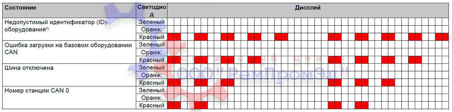 |
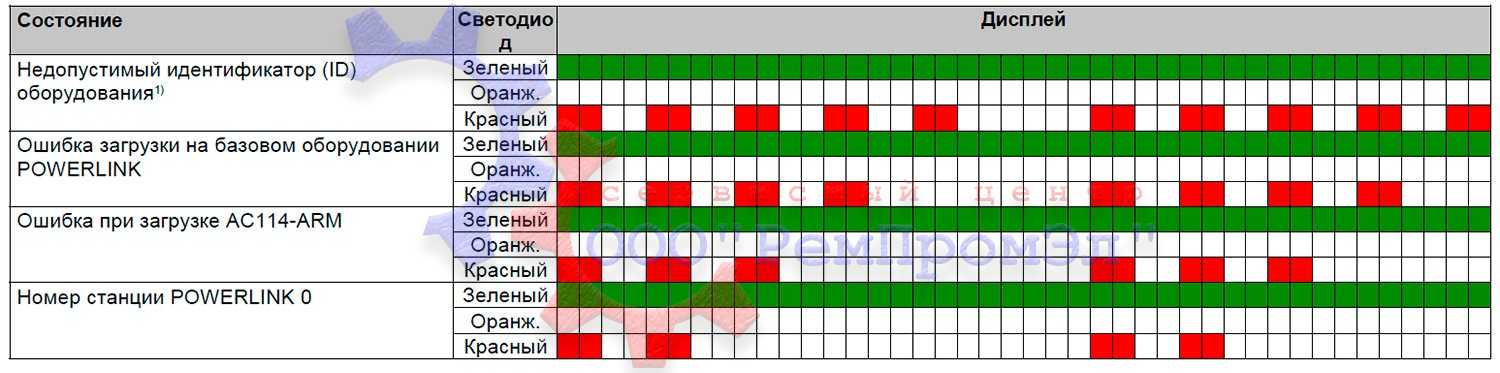 |
Возможные ошибки:
|
|
Все возможные ошибки сервопривода B&R ACOPOS 1010, 1016, 1022, 1045,1090, 1180, 1320, 1640, 128M — Скачать в формате PDF
Типы сервоприводов B&R ACOPOS
| Сервопривод | Тип сервопривода |
|---|---|
|
ACOPOS 1010, 1016 |
8V1010.00-2; 8V1010.001-2; 8V1010.50-2; 8V1010.501-2; 8V1016.00-2; 8V1016.001-2; 8V1016.50-2; 8V1016.501-2 |
| ACOPOS 1022, 1045, 1090 | 8V1022.00-2; 8V1022.001-2; 8V1045.00-2; 8V1045.001-2; 8V1090.00-2; 8V1090.001-2 |
| ACOPOS 1180, 1320 | 8V1180.00-2; 8V1180.001-2; 8V1320.00-2; 8V1320.001-2 |
| ACOPOS 1640, 128M | 8V128M.00-2; 8V128M.001-2; 8V1640.00-2; 8V1640.001-2 |
Указанные в таблице типы сервоприводов B&R ACOPOS это далеко не все, мы предлагаем качественный ремонт сервоприводов в Тольятти абсолютно любых производителей и года выпуска.
Оставить заявку на ремонт сервопривода B&R ACOPOS

Вы заинтересованы в качественном ремонте дорогостоящего промышленного оборудования силами специалистов нашего сервисного центра, Вы сделали правильный выбор, мы приложим максимум усилий для скорейшего восстановления вышедшего из строя серводрайвера, что позволит Вам максимально сократить простой оборудования и сэкономить значительную сумму.
У вас есть проблемы с сервоприводом? Вам нужен срочный ремонт сервопривода B&R ACOPOS или других серий? Оставьте заявку на ремонт сервопривода B&R ACOPOS в Тольятти воспользовавшись одноименной кнопкой на сайте либо обратитесь к нашим менеджерам. Связаться с ними можно несколькими способами:

- Заказав обратный звонок (кнопка в правом верхнем углу сайта)
- Посредством чата (кнопка расположена с левой стороны сайта)
- Позвонив по номеру телефона: +7(927)610-78-70; +7(848)255-80-30
- Написав на электронную почту: Адрес электронной почты защищен от спам-ботов. Для просмотра адреса в вашем браузере должен быть включен Javascript.
- Перейти в начало статьи
|
|
#1 |
|
Member
Join Date: Feb 2012 Location: Cashel Posts: 2 |
B & R ACOPOS 1090 error Hi, what is the reason servo drive acopos 1090 ready GREEN LED blinking? cannot find the error on any manuals. please help |
|
|
|


|
|
#2 |
|
Member
Join Date: May 2012 Location: Beer Posts: 4 |
Quote:
Originally Posted by BLESSEN12 Hi, what is the reason servo drive acopos 1090 ready GREEN LED blinking? cannot find the error on any manuals. please help Hi, You can change Capacitor value 0.033uF/275Vac. Email:langsun2009@Hotmail.com
Last edited by kp2009; May 17th, 2012 at 03:41 AM.
|
|
|
|


|
|
#3 |
|
Member
Join Date: May 2012 Location: Beer Posts: 4 |
.. |
|
|
|
|
|
#4 |
|
Member
Join Date: Sep 2012 Location: algeria Posts: 1 |
probl�me with acopos 1090 السلام عليكم Hi, what is the reason servo drive acopos 1090 with module plugin C114 error LED blinking? cannot find the error on any manuals. please help plis..
|
|
|
|

|
|
#5 |
|
Lifetime Supporting Member + Moderator
Join Date: Sep 2010 Location: In The VAT Shed Posts: 720 |
Which error LED is blinking, the one on the drive or the LED on the module, and what colour is it blinking. Mark |
|
|
|

|
|
#6 |
|
Member
Join Date: Nov 2012 Location: Minneapolis, MN Posts: 1 |
Quote:
Originally Posted by kp2009 Hi, You can change Capacitor value 0.033uF/275Vac. Email:langsun2009@Hotmail.com
THANK YOU for this information! It solved our problem with the same drive. THANK YOU, THANK YOU, THANK YOU!! Dave In Minneapolis
Last edited by DaveInMinneapolis; November 3rd, 2012 at 01:45 PM. Reason: typo & format
|
|
|
|

|
|
#7 |
|
Member
Join Date: May 2012 Location: Beer Posts: 4 |
…. |
|
|
|
|
|
#8 |
|
Member
Join Date: Feb 2013 Location: malaysia Posts: 10 |
hi, please need help thank you |
|
|
|

|
|
#9 |
|
Member
Join Date: Feb 2013 Location: malaysia Posts: 10 |
hi, kp2009 i have check that capacitor 3 units, in the my driver is not 0.033uf its 1uf/400vac i have remove that capacitor and measure with LCR meter,but its showing that 0.689 for the 2psc and the another one is show 0.989uf so can you please tell me is that is will ok or any other probelmis in the PCB? PLEASE I NEED YOUR HELP THANK YOU |
|
|
|
|
|
#10 |
|
Member
Join Date: Feb 2013 Location: Bolton Posts: 5 |
Hi, If you require any industrial repairs, please email me electronics@neutronictechnologies.com |
|
|
|
|
|
#11 |
|
Member
Join Date: Feb 2013 Location: malaysia Posts: 10 |
Andy M DEAR FRIEND, as you said have 3 psc of gray color capacitor is correct, but the value of capacitor is 1uf/400v its not the 33nf thank you . |
|
|
|
|
|
#12 |
|
Member
Join Date: Feb 2013 Location: Bolton Posts: 5 |
If you are sure you are looking at the right capacitor then any that do not measure correctly are faulty. Polyester capacitors of this nature should be very accurate and so should measure their printed value. |
|
|
|
|
|
#13 |
|
Member
Join Date: Feb 2013 Location: Bolton Posts: 5 |
Attach a photo showing the 3 capacitors you are looking at please |
|
|
|
|
|
#14 |
|
Member
Join Date: Feb 2013 Location: malaysia Posts: 10 |
Andy M DEAR SIR, i would take picture and send to you by tomorrow ,i am sorry now the OFFLINE ,THANK YOU SIR. THANKS FOR REPLY SIR. |
|
|
|
|
|
#15 |
|
Member
Join Date: Feb 2013 Location: Bolton Posts: 5 |
Photo attatched with bottom filter board removed, the 3 capacitors are actually removed here but you can see where they go |
|
|
|

ACOPOS Error Texts
The ACOPOS error texts are described as follows:
1: Invalid parameter ID
Description: Response error while writing or reading an invalid parameter ID. Reaction: None. Cause/Remedy: See error number 1002.
2: Data block for upload is not available
Description: Response error during initialization of an NC system module data block upload (data block read access). The corresponding NC system module (‘acp10sys.br’ or ‘acp10bsl.br’) is not present on the drive. Reaction: Data block read access is not initialized. Cause/Remedy: The NC system module was not saved on the drive. See error number 32018.
<error number>: <error text>
Description: Exact description of error.
Reaction: Description of the reaction of the ACOPOS servo drive, which is triggered by the error.
Cause/Remedy: Description of the cause of error as well as the possibilities for correcting this error.
Info:Description of the additional information output with the error message.
Data type: Data format
Info:
Data type:
Info:
Data type:
Pagina 1 di 164ACOPOS Error Texts
18/04/2007file://C:Documents and SettingscovattaImpostazioni localiTemp~hhE9C7.htm

3: Write access for a read-only parameter
Description: Response error while writing a parameter, which does not allow a change in the value. Reaction: The parameter value is not accepted. Cause/Remedy: See error number 1002.
4: Read access for a write-only parameter
Description: Response error while reading a parameter, which does not allow read access. Reaction: The parameter value is not passed on. Cause/Remedy: See error number 1002.
8: Data block read access already initialized
Description: Response error during initialization of a data block read access (upload), if the previous transfer has not yet been completed. Reaction: Data block read access is not initialized for the parameter ID. Cause/Remedy: Sequence error during data block download. See also error number 1002.
9: Data block write access already initialized
Description: Response error during initialization of a data block write access (download), if the previous transfer has not
Info:
Data type:
Info:
Data type:
Info:
Data type:
Info:
Data type:
Pagina 2 di 164ACOPOS Error Texts
18/04/2007file://C:Documents and SettingscovattaImpostazioni localiTemp~hhE9C7.htm

yet been completed. Reaction: Data block write access is not initialized for the parameter ID. Cause/Remedy: Sequence error during data block download. See also error number 1002.
10: Data block read access not initialized
Description: Response error while reading a data segment (RD_BLOCK_SEGM, RD_BLOCK_LAST_SEGM), if no data block upload was initialized. Reaction: No data is passed on. Cause/Remedy: See error number 8.
11: Data block write access not initialized
Description: Response error while writing a data segment (WR_BLOCK_SEGM, WR_BLOCK_LAST_SEGM), if no data block download was initialized. Reaction: No data is saved. Cause/Remedy: See error number 9.
16: The data segment is already the last when reading the data block
Description: Response error while reading a data segment (RD_BLOCK_SEGM), if the initialized length of the upload data has already been transferred. The last data segment must be transferred with its own parameter ID (RD_BLOCK_LAST_SEGM). Reaction: The data block upload is aborted. Cause/Remedy:
Info:
Data type:
Info:
Data type:
Info:
Data type:
Pagina 3 di 164ACOPOS Error Texts
18/04/2007file://C:Documents and SettingscovattaImpostazioni localiTemp~hhE9C7.htm

See error number 8.
17: The data segment is already the last when writing the data block
Description: Response error while writing a data segment (RD_BLOCK_SEGM), if the initialized length of the download data has already been transferred. The last data segment must be transferred with its own parameter ID (WR_BLOCK_LAST_SEGM). Reaction: The data block download is aborted. No data is saved. Cause/Remedy: See error number 9.
18: The data segment is not yet the last when reading the data block
Description: Response error while reading the last data segment (RD_BLOCK_LAST_SEGM), if enough upload data has not yet been transferred for the initialized length. Reaction: The data block upload is aborted. Cause/Remedy: See error number 8.
19: The data segment is not yet the last when writing the data block
Description: Response error while writing the last data segment (WR_BLOCK_LAST_SEGM), if enough download data has not yet been transferred for the initialized length. Reaction: The data block download is aborted. No data is saved. Cause/Remedy: See error number 9.
21: Checksum after data block write is invalid
Info:
Data type:
Info:
Data type:
Info:
Data type:
Info:
Pagina 4 di 164ACOPOS Error Texts
18/04/2007file://C:Documents and SettingscovattaImpostazioni localiTemp~hhE9C7.htm

Description: Response error in BsLoader mode during the data block download of an NC system module (‘acp10sys.br’ or ‘acp10bsl.br’). The checksum of the NC system module (B&R module) is invalid. Reaction: See error number 25. Cause/Remedy: See error number 32018. See error number 1012.
23: Parameter ID in data block is invalid (data block write)
Description: Response error in BsLoader mode during the data block download of an NC system module (‘acp10sys.br’ or ‘acp10bsl.br’). The parameter ID of the data block does not match the parameter ID entered to the B&R module header of the transferred NC system module. Reaction: See error number 25. Cause/Remedy: The transferred data block is an invalid NC system module. A BsLoader (‘acp10bsl.br’) was transferred during the operating system download. An operating system (‘acp10sys.br’) was transferred during the BsLoader download. See error number 32018.
25: Burn system module only allowed immediately after download
Description: Response error in BsLoader mode during the ‘burn NC system module’ command. There is no valid NC system module (‘acp10sys.br’ or ‘acp10bsl.br’) present on the drive or the burn command was not executed immediately following the NC system module download. Reaction: NC system module is identified as invalid and cannot be saved (burned to the FLASH memory). Cause/Remedy: NC system module download was not executed. NC system module is malfunctioning, is invalid or is incompatible. Sequence error during NC system module download. See also error number 32018.
27: Operating system not able to be started (operating system is not on the FPROM)
Data type:
Info: Parameter ID
Data type: ‘PARID’
Info:
Data type:
Pagina 5 di 164ACOPOS Error Texts
18/04/2007file://C:Documents and SettingscovattaImpostazioni localiTemp~hhE9C7.htm

Description: Response error during command for changing the boot state, ‘start operating system’. There is no operating system saved on the drive. Reaction: The operating system is not started. Cause/Remedy: See error number 32018.
40: Value of parameter higher than maximum value
Description: Response error while writing a parameter, if the value is larger than the upper limit for this parameter. Reaction: The parameter value is not accepted. Cause/Remedy: See error number 1002.
41: Value of parameter higher than maximum value
Description: See error number 40. Reaction: See error number 40. Cause/Remedy: See error number 40.
42: Value of parameter higher than maximum value
Description: See error number 40. Reaction: See error number 40.
Info:
Data type:
Info: Maximum value
Data type: REAL
Info: Maximum value
Data type: UDINT
Info: Maximum value
Data type: DINT
Pagina 6 di 164ACOPOS Error Texts
18/04/2007file://C:Documents and SettingscovattaImpostazioni localiTemp~hhE9C7.htm

Cause/Remedy: See error number 40.
52: Value of parameter lower than minimum value
Description: Response error while writing a parameter, if the value is smaller than the lower limit for this parameter. Reaction: The parameter value is not accepted. Cause/Remedy: See error number 1002.
53: Value of parameter lower than minimum value
Description: See error number 52. Reaction: See error number 52. Cause/Remedy: See error number 52.
54: Value of parameter lower than minimum value
Description: See error number 52. Reaction: See error number 52. Cause/Remedy: See error number 52.
64: Hardware ID in B&R module is invalid (data block write)
Description:
Info: Minimum value
Data type: REAL
Info: Minimum value
Data type: UDINT
Info: Minimum value
Data type: DINT
Info: Hardware ID
Data type: USINT
Pagina 7 di 164ACOPOS Error Texts
18/04/2007file://C:Documents and SettingscovattaImpostazioni localiTemp~hhE9C7.htm

Response error in BsLoader mode during the download of an NC system module (‘acp10sys.br’ or ‘acp10bsl.br’). The hardware ID in the B&R module header of the NC system module is invalid or incompatible to the ACOPOS hardware. Reaction: See error number 25. Cause/Remedy: The NC system module cannot be supported by the ACOPOS hardware. See error number 32018.
65: Hardware version in B&R module is invalid (data block write)
Description: Response error in BsLoader mode during the download of an NC system module (‘acp10sys.br’ or ‘acp10bsl.br’). The hardware version in the B&R module header of the NC system module is not compatible with the hardware version of the drive. Reaction: See error number 25. Cause/Remedy: Incorrect operating system version or BsLoader version: BsLoader V047 or operating system V110 is not allowed to be loaded on an ACOPOS servo drive 8Vxxxx.00-1. BsLoader V0381 or operating system V0390 is not allowed to be loaded on an ACOPOS servo drive 8Vxxxx.xx-2. See error number 32018.
66: The operating system on the drive is incompatible to the existing network
Description: Response error in BsLoader mode during the ‘change boot state’ command. The operating system cannot be started because the saved operating system does not support the existing network. Hardware ID of operating system: 80h…CAN operating system 81h…Powerlink operating system Reaction: The command is not executed. Cause/Remedy: A Powerlink operating system is saved on a drive with a CAN network card (AC110 plug-in card). A CAN operating system is saved on a drive with a Powerlink network card (AC112 plug-in card). See error number 32018.
67: Necessary parameter is missing or is invalid
Info: Hardware Revision
Data type: USINT
Info: Hardware ID of operating system
Data type: USINT
Pagina 8 di 164ACOPOS Error Texts
18/04/2007file://C:Documents and SettingscovattaImpostazioni localiTemp~hhE9C7.htm

Description: Response error while writing the parameter. A parameter, which is necessary for the assignment, was not configured or was configured incorrectly Reaction: Parameter value is not accepted. Cause/Remedy: Parameters were configured in wrong order. Dependent parameters are missing or were before invalidly configured. Example: If when switching on the external bleeder not all parameters of the external bleeder were valid configured, then this error is sent.
68: Data block length invalid
Description: Reaction: Cause/Remedy:
1001: Error-FIFO overflow
Description: The FIFO for error messages on the ACOPOS is full. Only runtime errors are entered in this error FIFO. Response errors are directly sent as response to parameter write or read. Reaction: Further error messages are lost. Cause/Remedy: Via the network; — no errors are being read or — errors are being read too slowly. On the ACOPOS; — too many errors are being entered or — errors are being entered too quickly. See additionally entered error numbers.
1002: Parameter outside the valid range
Info: Parameter ID
Data type: ‘PARID’
Info:
Data type:
Info:
Data type:
Pagina 9 di 164ACOPOS Error Texts
18/04/2007file://C:Documents and SettingscovattaImpostazioni localiTemp~hhE9C7.htm

Description: Response error while writing a parameter if the value is outside the valid limits. Reaction: The parameter value is not accepted. Cause/Remedy: Incorrect parameter ID being used for the desired function. The value is not a valid constant or is not in the allowed selection list. The value exceeds or does not meet the limits for implementation. The value is outside of a physically possible range (e.g. negative time). The data type or data length for this parameter ID is incorrect. Network transfer error. See also error number 1012.
1003: Parameter cannot be written while loop control is active
Description: Response error while writing a parameter, which does not allow a change in the value when the controller is active. Reaction: The parameter value is not accepted. Cause/Remedy: The parameter was written too late (after the ‘switch on controller’ command). The ‘switch off controller’ command is missing or was not executed in the drive state (movement active). Request (delay step) for ‘controller off’ state is missing. -> Check program sequence and status request.
1004: Timeout in network life sign monitor
Description: Runtime error during active network life sign monitoring, if no cyclic telegram arrives for a specified amount of time (NETWORK_LIVE_CTRL). See also error number 4005. Reaction: All digital outputs (AC130, AC131) are deactivated, (i.e. the output levels are set to LOW and all switchable IOs are set to input). When ‘switch on controller’ command: See error number 4005. When controller is active: See error number 1011. Cause/Remedy: Problem in network life sign monitor:
Info:
Data type:
Info:
Data type:
Info:
Data type:
Pagina 10 di 164ACOPOS Error Texts
18/04/2007file://C:Documents and SettingscovattaImpostazioni localiTemp~hhE9C7.htm

Time for network life sign monitoring NETWORK_LIVE_CTRL is defined too short. Network life sign monitoring is activated too early, before cyclic telegrams are sent. Problem in network data transfer: Cycle time exceeded, extremely high computing time load or failure of the controller CPU. Disturbance or disconnection of the network connection. See wiring guidelines error number 7030. The network load is too high.
1005: Parameter cannot be written while a movement is active
Description: Response error while writing a parameter, which does not allow a change in the value when a movement is active. Reaction: The parameter value is not accepted. Cause/Remedy: The parameter was written too late, after a movement start command. Request (delay step) for ‘move complete’ state is missing. -> Check program sequence and status request.
1006: Invalid parameter for trigger event (digital input + edge)
Description: Response error while writing an event parameter if the value is an invalid digital input or an invalid trigger edge. Reaction: The parameter value is not accepted. Cause/Remedy: See error number 1002.
1007: Master for network coupling deactivated — one master is already sending
Description: Runtime error when sending cyclic master data (positions) for a network coupling if data is also received at the same CAN ID (MA1/2/3_CYCLIC_SEND). Reaction: The transmission of data is deactivated for this coupling object, to prevent a CAN-BUS-OFF or position jumps.
Info:
Data type:
Info:
Data type:
Info:
Data type:
Pagina 11 di 164ACOPOS Error Texts
18/04/2007file://C:Documents and SettingscovattaImpostazioni localiTemp~hhE9C7.htm

Cause/Remedy: The transmission of data to this coupling object was also activated for another master (network nodes). Another device is sending telegrams to the CAN-IDs of the ACOPOS network coupling (125, 126, 127).
1008: Master for network coupling deactivated — Encoder error
Description: Runtime error when sending cyclic master data for a network coupling if actual positions are sent and the corresponding encoder sends an error (MA1/2/3_CYCLIC_SEND). Reaction: The transmission of data is deactivated for this coupling object, to prevent position jumps. Cause/Remedy: See additionally entered encoder error numbers.
1009: Error during memory allocation
Description: Response error in dynamic memory management if there is not enough memory for the requested function. Reaction: The most recently requested function is not executed. The download data is not saved. The parameter value is not accepted. Cause/Remedy: An individual memory area is too large or too much memory was being used: cam profile data download, parameter sequence download, EPROM data download, creation of function block (FUNCTION_BLOCK_CREATE), when writing parameters with memory allocation (CAMCON_MAX_CAM, FIFO_MAX_LENGTH)
1011: Quickstop input active
Description: Runtime error in quickstop function if the configured digital input is active. See also error number 4005. Reaction: The ‘controller ready’ state is reset.
Info:
Data type:
Info:
Data type:
Info:
Data type:
Pagina 12 di 164ACOPOS Error Texts
18/04/2007file://C:Documents and SettingscovattaImpostazioni localiTemp~hhE9C7.htm

When ‘switch on controller’ command: See error number 4005. When position control is active (CONTROLLER_MODE=1 or 3): Movement stopped with the axis limits and by switching off the controller. When speed control is active (CONTROLLER_MODE=2): See error number 4007. When U/f control is active (CONTROLLER_MODE=7): Movement stopped with speed controlled ramp, with axis limits and by switching off the controller. When current control is active with commutation (CONTROLLER_MODE=4): Movement stopped with the current limits and by switching off the controller. Cause/Remedy: See error number 6021.
1012: Breakdown of cyclic network communication
Description: Runtime error if the Firmware for the AC112 network card detects a failure in the cyclic Powerlink communication. See error number 4005. Reaction: See error number 1004. Cause/Remedy: Network cabling interruption. Powerlink station has failed or is switched off. Too many stations wired together (maximum number of HUB layers, maximum network cable length). Too many stations for the configured Powerlink cycle time. Environmental temperature outside the valid range. Network plug-in card (AC112) is defective or wrong HW revision. In the event of network disturbances: See wiring guidelines error number 7030
1013: Station is not available for network communication
Description: Error configuring cyclic receive data if the network station for a coupling is not available (CONFIG_MA1/2/3/4/5_CYCLIC_POS). Reaction: The cyclic data (position) is not available on the corresponding parameter ID (MA1/2/3/4/5_CYCLIC_POS) and is not updated. Cause/Remedy: Invalid station number. The configuration was written too early. The station is not yet on the network or has failed.
Info:
Data type:
Info: Station number
Data type: UINT
Pagina 13 di 164ACOPOS Error Texts
18/04/2007file://C:Documents and SettingscovattaImpostazioni localiTemp~hhE9C7.htm

See also error number 1012.
1014: Network command interface is occupied
Description: Error configuring cyclic receive data if the processing of the last command is not finished yet (CONFIG_MA1/2/3/4/5_CYCLIC_POS). Reaction: The configuration of the network coupling is not accepted. Cause/Remedy: The configuration for this coupling object was written sveral times too fast one after the other.
1016: Maximum cycle time exceeded — CPU load too high
Description: Runtime error while processing the mid-priority operating system functions if the computing time load on the ACOPOS is too high (e.g. set value generation, network processing and function blocks are no longer completed with the position controller cycle of 400us). The high priority controller functions are further processed with a rigid cycle. Reaction: Depending on the duration and the degree by which the cycle time is exceeded, subsequent errors can occur (e.g. speed jumps and lag errors). Cause/Remedy: Too many function blocks (FUNCTION_BLOCK_CREATE).
1017: Invalid parameter ID for cyclic read access
Description: Response error configuring a cyclic read access or a data connection using pointer parameter ID. Reaction: The parameter ID is not accepted. Cause/Remedy: Invalid parameter ID, the data type is not supported (composite data type or not a 4 byte value). Read access not allowed or parameter with a computing-intensive read function.
1018: Invalid parameter ID for cyclic write access
Info:
Data type:
Info:
Data type:
Info: Parameter ID
Data type: ‘PARID’
Pagina 14 di 164ACOPOS Error Texts
18/04/2007file://C:Documents and SettingscovattaImpostazioni localiTemp~hhE9C7.htm

Description: Response error configuring a cyclic write access or a data connection using pointer parameter ID. Reaction: The parameter ID is not accepted. Cause/Remedy: Write access not allowed. Write access not allowed when controller is active or when a movement is active. See also error number 1017.
1021: Parameter cannot be written: Function block active
Description: Response error while writing a parameter, which does not allow a change in the value when the corresponding function block is active. Reaction: The parameter value is not accepted. Cause/Remedy: The function block does not support an ‘online’ change of this parameter. The function block is active in a certain operating state, which does not allow an ‘online’ change of this parameter (e.g. MPGEN in a compensation movement). The parameter was written too late, after activation of the function block or operating state. The function block was not deactivated before writing the parameter or a status request is missing.
2001: Upload of trace data not allowed: Recording active
Description: Response error during initialization of the data upload (data block read access) if a trace is still active. Reaction: Data block read access is not initialized. The upload cannot be executed. Cause/Remedy: Due to a long recording time or because the trigger event has not occurred, the previous trace has not yet ended. Status request for ‘end trace’ missing. The ‘stop trace’ command is missing. -> Check trace parameter for the trigger condition.
2003: Trace start not allowed: Recording active
Info: Parameter ID
Data type: ‘PARID’
Info:
Data type:
Info:
Data type:
Pagina 15 di 164ACOPOS Error Texts
18/04/2007file://C:Documents and SettingscovattaImpostazioni localiTemp~hhE9C7.htm

Description: Response error using ‘Start trace’ command if a trace is already active. Reaction: This does not interrupt the active trace. Cause/Remedy: See error number 2001.
2004: Trace start not allowed: No trace test data defined
Description: Response error using ‘Start trace’ command if no test data has been configured for the trace. Reaction: The trace is not started. Cause/Remedy: Invalid parameter ID for test data.
2006: Initialization of trace parameters not allowed: Recording active
Description: Response error while writing a parameter if a trace is active. ‘Online’ changes cannot be made to the trace parameter. Reaction: The parameter value is not accepted. This does not interrupt the active trace. Cause/Remedy: The parameter was written too late, after the ‘start trace’ command. See error number 2001.
4005: Controller cannot be switched on: Drive in error state
Description: Response error while switching on the controller if the drive is in an error state. The error LED indicates the ‘controller not ready’ state. Additionally, a runtime error is entered, which provides detailed information about the cause of error. (e.g. error number 1011). This error entry can also be triggered using a separate
Info:
Data type:
Info:
Data type:
Info:
Data type:
Info:
Data type:
Pagina 16 di 164ACOPOS Error Texts
18/04/2007file://C:Documents and SettingscovattaImpostazioni localiTemp~hhE9C7.htm

command (CMD_ERR_STATE_INTO_FIFO). Reaction: The power level is not enabled and the controller is not switched on. Cause/Remedy: See additionally entered error numbers.
4007: Lag error stop limit exceeded
Description: Runtime error when position controller is active if the lag error PCTRL_LAG_ERROR exceeds the configured lag error limit value AXLIM_DS_STOP. Reaction: Movement stopped with speed regulated ramp, with axis limits and by switching off the controller. Cause/Remedy: Lag error limit too small (AXLIM_DS_STOP). Incorrect controller configuration: — Controller is set too weak. — Feed forward incorrectly configured (e.g. prediction time = 0). — Unstable control loop. Current limiting: — Increased current. See error number 9030. — EMF: Operating speed too high and/or network voltage too low. Check if the motor is being run within the voltage limit sqrt(ICTRL_USD_REF^2+ ICTRL_USQ_REF^2) > UDC_ACT/sqrt(3). — Current limiting: Check if the current ICTRL_ISQ_REF is limited with the limits sqrt(2)* MOTOR_CURR_MAX or sqrt(2)* ACOPOS_CURR_MAX. — Recovery power limiter: Check if UDC_ACT > UDC_BLEEDER_ON and ICTRL_ISQ_REF = ISQ_MAX_UDC and ICTRL_ISQ_REF = ISQ_MIN_UDC. — Under-voltage limiter: Check if UDC_ACT < UDC_NOMINAL and ICTRL_ISQ_REF = ISQ_MAX_UDC and ICTRL_ISQ_REF = ISQ_MIN_UDC. — Temperature limiter: The current is limited when movement is stopped due to over-temperature on junction. See error number 9030. — Torque limiting: Check if the torque TORQUE_ACT is limited with the 4 quadratic torque limiter (LIM_T1_POS, LIM_T1_NEG, LIM_T2_POS, LIM_T2_NEG). Speed limiting: — Speed controller. Check if the speed SCTRL_SPEED_REF is limited with the limits SCTRL_LIM_V_POS, SCTRL_LIM_V_NEG or MOTOR_SPEED_MAX. — Position controller. Check if the speed PCTRL_V_ACT is limited with the limit POS_CTRL_P_MAX. Encoder position or speed contains an error: See error number 4014. Motor wiring error: See error number 6045. Motor defect: See error number 6045. ACOPOS defect: See error number 6045.
4008: Positive limit switch reached
Info: Current lag error
Data type: REAL
Info:
Pagina 17 di 164ACOPOS Error Texts
18/04/2007file://C:Documents and SettingscovattaImpostazioni localiTemp~hhE9C7.htm

Description: Runtime error when movement is active if the positive limit switch is reached in the positive direction of movement. Reaction: Movement stopped with the axis limits. The controller remains switched on. Cause/Remedy: Movement command without target position or with incorrect target position. SW limits are deactivated or are defined too large. Slave movement range for cam automats is too large. When slowly «exiting» a closed limit switch with the cam automats if the master position does not increase steadily. See also error number 4010.
4009: Negative limit switch reached
Description: Runtime error when movement is active if the negative limit switch is reached in the negative direction of movement. Reaction: Movement stopped with the axis limits. The controller remains switched on. Cause/Remedy: See error number 4008.
4010: Controller cannot be switched on: Both limit switches are closed
Description: Response error using the ‘switch on controller’ command if the positive and negative limit switches are closed. Reaction: The command is not executed. Cause/Remedy: The active input level of the limit switch is inverted. Limit switch falsely closed due to an ‘external force’ (mechanically blocked, closed manually). Falsely closed due to HW error (wire break, line termination, wiring error, supply voltage). For ‘endless axes’ or ‘cyclic axes’ without limited movement range and without end switch: Monitoring of the limit switch can also be deactivated (LIMIT_SWITCH_IGNORE) for an alternative use of the digital inputs.
Data type:
Info:
Data type:
Info:
Data type:
Pagina 18 di 164ACOPOS Error Texts
18/04/2007file://C:Documents and SettingscovattaImpostazioni localiTemp~hhE9C7.htm

4011: Controller cannot be switched off: Movement active
Description: Response error using ‘switch off controller’ command if a movement is active. Reaction: The command is not executed. This does not interrupt the active movement. Cause/Remedy: The command was written too soon after a movement stop. Request (delay step) for ‘move complete’ state is missing. -> Check program sequence and status request.
4012: Controller cannot be switched on: Init parameters missing or not valid
Description: Response error using ‘switch on controller’ command if at least one Init parameter is missing or was set to an invalid value. Reaction: The command is not executed. Cause/Remedy: The command was written too soon in the initialization phase, before the configuration was completed. Parameter initialization or request (delay step) for ‘Global init’ state is missing. -> Check program sequence and status request.
4014: Two encoder control: Stop limit of positions difference exceeded
Description: Runtime error when two-encoder position control is active. The difference between position encoder position and motor encoder position is greater than AXLIM_DS_STOP2. Reaction: See error number 4007. Cause/Remedy: Error in the motor/position encoder configuration. Tolerances in the drive mechanics (fluctuations in the spindle slope, backlash, thermal expansions in the power transmission system, high accelerations and low rigidity in power transmission system) require a larger AXLIM_DS_STOP2. Defective drive mechanics (slip, coupling break)
Info:
Data type:
Info: Parameter ID
Data type: ‘PARID’
Info: Current positions difference
Data type: REAL
Pagina 19 di 164ACOPOS Error Texts
18/04/2007file://C:Documents and SettingscovattaImpostazioni localiTemp~hhE9C7.htm

Encoder position or speed contains an error: Encoders which were not detected by the position encoder monitor or motor encoder monitor. Check UP/DOWN LED on the encoder plug-in card and encoder position PCTRL_S_ACT. Encoder does not meet the specifications of the plug-in card (compare the user’s manual and the encoder data sheet). Encoder connection is interrupted or defective. See wiring guidelines error number 7030. Encoder supply defect. Encoder defective. Plug-in card defective. Resolver signal disturbance. See error number 7045. Resolver signal disturbance. See error number 39002.
5001: Target position exceeds positive SW limit
Description: Response error at the start of a movement if the requested target position is larger than the positive SW limit. Response error when a movement in the positive direction is active if the current position is already outside of the positive SW limits. Reaction: The requested movement start is not executed. This will not interrupt an active movement. Cause/Remedy: SW limit incorrectly configured. Incorrect target position. Incorrect movement command. The monitor of the SW limits can also be deactivated (SGEN_SW_END_IGNORE) for ‘endless axes’ or ‘cyclic axes’ without limited movement range.
5002: Target position exceeds negative SW limit
Description: Response error at the start of a movement if the requested target position is smaller than the negative SW limit. Response error when a movement in the negative direction is active if the current position is already outside of the negative SW limits. Reaction: See error number 5001. Cause/Remedy: See error number 5001.
5003: Positive SW limit reached
Info:
Data type:
Info:
Data type:
Info:
Pagina 20 di 164ACOPOS Error Texts
18/04/2007file://C:Documents and SettingscovattaImpostazioni localiTemp~hhE9C7.htm

Description: Runtime error when movement is active if the braking range of the positive SW limit has been reached and the set speed is 0. Reaction: The movement is deactivated. The controller remains switched on. Cause/Remedy: Incorrect movement command without absolute target position (movement in positive direction). Positive SW limit incorrectly configured. Cam automat: The set value generation is too dynamic (speed or acceleration is too high) for the axis limit AXLIM_A2_POS and therefore exceeds the range of the ‘braking parabola’ on the positive SW limit. See also error number 5001.
5004: Negative SW limit reached
Description: Runtime error when movement is active if the braking range of the negative SW limit has been reached and the set speed is 0. Reaction: The movement is deactivated. The controller remains switched on. Cause/Remedy: See error number 5003. Negative SW limit incorrectly configured. Cam automat: The set value generation is too dynamic (speed or acceleration is too high) for the axis limit AXLIM_A2_NEG and therefore exceeds the range of the ‘braking parabola’ on the negative SW limit. See also error number 5001.
5005: Start of movement not possible: Position controller inactive
Description: Response error when starting a movement if the position controller is not active. Reaction: The requested movement start is not executed. Cause/Remedy: ‘Switch on controller’ command is missing. Request (delay step) for ‘controller on’ state is missing. The controller was switched off due to a drive error. The controller was activated in a mode without position control, e.g. speed control. Check CONTROLLER_MODE. The enable input PCTRL_ENABLE_PARID deactivates position control.
Data type:
Info:
Data type:
Info:
Data type:
Pagina 21 di 164ACOPOS Error Texts
18/04/2007file://C:Documents and SettingscovattaImpostazioni localiTemp~hhE9C7.htm

5006: Start of movement not possible: Axis not referenced
Description: Response error when starting a movement if the home position is not valid. Reaction: The requested movement start is not executed. Cause/Remedy: The ‘reference’ command is missing. The status request (delay step) for ‘reference completed’ is missing. The referencing procedure was aborted due to an error. The monitor for ‘reference’ can also be deactivated (SGEN_SW_END_IGNORE) for ‘endless axes’ or ‘cyclic axes’ without limited movement range.
5010: Move in pos. direction not possible: Pos. limit switch is closed
Description: Response error when starting a movement. The positive limit switch is closed and the requested movement is moving in the positive direction. Reaction: The requested movement start is not executed. Cause/Remedy: Movement command or target position incorrect. See also error number 4010.
5011: Move in neg. direction not possible: Neg. limit switch is closed
Description: Response error when starting a movement. The negative limit switch is closed and the requested movement is moving in the negative direction. Reaction: See also error number 5010. Cause/Remedy: See also error number 5010.
5012: Start of movement not possible: Stop ramp active
Info:
Data type:
Info:
Data type:
Info:
Data type:
Info:
Pagina 22 di 164ACOPOS Error Texts
18/04/2007file://C:Documents and SettingscovattaImpostazioni localiTemp~hhE9C7.htm

Description: Response error when starting a movement if a movement stop is active. Reaction: The requested movement start is not executed. Cause/Remedy: Missing status request (delay step) following a stop command. The movement stop was triggered by a drive error. A movement can also be started in the deceleration ramp after the ‘halt basis movement’ command.
5013: Cyclic set value mode cannot be switched on: Movement active
Description: Response error when switching on the operating mode ‘cyclic, external set values’ (CMD_CYC_SET_VALUE_MODE) if a drive-controlled movement is active. A movement must first be decelerated to standstill so that the new operating mode can be initialized and a set value generator external to the drive can be applied without any jumps. Reaction: The operating mode ‘cyclic, external set values’ is not activated. The current movement is not interrupted. Cause/Remedy: A referencing procedure or a basis movement is started and the status request (delay state) for ‘move complete’ is missing.
5015: Start of movement not possible: Homing procedure active
Description: Response error using movement-start command if a homing procedure is active. Reaction: The requested movement start is not executed. This does not interrupt the homing procedure. Cause/Remedy: The status request (delay step) for ‘reference completed’ is missing. A homing procedure can be ended by a movement stop.
5016: Parameter cannot be written: Homing procedure active
Data type:
Info:
Data type:
Info:
Data type:
Info:
Data type:
Pagina 23 di 164ACOPOS Error Texts
18/04/2007file://C:Documents and SettingscovattaImpostazioni localiTemp~hhE9C7.htm

Description: Response error while writing a parameter if a homing procedure is active. ‘Online’ changes cannot be made to the homing parameter. Reaction: The parameter value is not accepted. This does not interrupt the active homing procedure. Cause/Remedy: The parameter was written too late, after the ‘start homing procedure’ command. -> Check program sequence and status request.
5017: Homing procedure mode not possible: Position controller inactive
Description: Response error using ‘start homing procedure’ command. A homing mode was defined, which requires a movement and is therefore only possible when control is active (e.g. homing mode ncSWITCH_GATE). Reaction: The homing procedure is not started. The ‘homing position valid’ state is reset. Cause/Remedy: Incorrect homing mode. Homing mode ncDIRECT with reference pulse. ‘Switch on controller’ command is missing. Request (delay step) for ‘controller on’ state is missing. The controller was switched off due to a drive error.
5018: Homing procedure not possible: Movement active
Description: Response error using ‘start homing procedure’ command if a movement is active. Homing «on the fly» is not supported during an active movement. Reaction: See error number 5017. The currently active movement is not interrupted. Cause/Remedy: Movement stop completed is missing. Request (delay step) for ‘move complete’ state is missing.
5019: Homing parameter outside the valid range
Info:
Data type:
Info:
Data type:
Info: Parameter ID
Data type: ‘PARID’
Pagina 24 di 164ACOPOS Error Texts
18/04/2007file://C:Documents and SettingscovattaImpostazioni localiTemp~hhE9C7.htm

Description: Response error when writing a homing parameter or using ‘start homing procedure’ command. An invalid configuration was detected. Reaction: The parameter value is not accepted. When ‘start homing procedure’ command: See error number 5017. Cause/Remedy: According to the parameter ID in the additional info.
5020: Homing procedure not possible: Both limit switches are closed
Description: Response error using ‘start homing procedure’ command. The positive and negative limit switches are closed. Reaction: See error number 5017. Cause/Remedy: See error number 4010.
5021: Limit switch closed: No direction change for this homing mode
Description: A homing mode was defined which does not allow a change of direction at the HW limits. Response error if a limit switch in the start direction is already closed (ncABS_SWITCH) when the ‘start homing procedure’ command is given. Runtime error during homing procedure if a limit switch signal occurred (ncABS_SWITCH, ncEND_SWITCH). Reaction: When ‘start homing procedure’ command: See error number 5017. When homing procedure: See error number 5035. Cause/Remedy: The HW limit was reached while searching for the edge of the absolute reference switch. -> HW error at reference switch (wire break, line termination, wiring error, supply voltage). The reference switch is mounted too close to the limit switch. See also error number 4010.
5022: Second limit switch signal received: Reference switch not found
Info:
Data type:
Info:
Data type:
Info:
Data type:
Pagina 25 di 164ACOPOS Error Texts
18/04/2007file://C:Documents and SettingscovattaImpostazioni localiTemp~hhE9C7.htm

Description: Runtime error during homing procedure if a limit switch signal has already occurred two times. Reaction: See error number 5035. Cause/Remedy: When searching for a reference switch edge or a reference pulse, the entire range between positive and negative end switch was covered. -> HW error at reference switch or encoder (wire break, line termination, wiring error, supply voltage). False triggering at a limit switch due to ‘bounce’. See also error number 4010.
5023: Incorrect limit switch signal received for current movement direction
Description: Runtime error during homing procedure if the negative limit switch signal is reached in the positive direction or if the positive limit switch signal is reached in the negative direction. Reaction: See error number 5035. Cause/Remedy: The reference switch is mounted too close to the limit switch. See also error number 4010.
5024: Cyclic set value mode aborted: Set positions missing
Description: Runtime error in the operating mode, ‘cyclic, external set values’. Linear extrapolation occurs if a new set position (CYC_MASTER_SET_POS) is not received within the master cycle. This error is registered if this failure occurs several times consecutively. Reaction: Movement stopped with the axis limits and by switching off the controller. Cause/Remedy: The operating mode ‘cyclic, external set values’ is activated too early, before set values are sent. See error number 5110.
5025: Homing offset with counting range correction cannot be set
Description: Response error using ‘start homing procedure’ command. A homing mode was defined with counting range
Info:
Data type:
Info:
Data type:
Info:
Data type:
Pagina 26 di 164ACOPOS Error Texts
18/04/2007file://C:Documents and SettingscovattaImpostazioni localiTemp~hhE9C7.htm

correction (+ncCORRECTION). Automatic correction of the homing offset cannot be performed because the encoder counting range with overflow is not unique in the entire movement range. Reaction: See error number 5017. Cause/Remedy: The maximum encoder counting range is smaller than the movement range between the SW limits. -> Difference between the SW limits is too large. Load scaling (units per motor revolutions) is too small. No absolute encoder (incremental encoder), encoder counting range is too small (e.g. only ‘Single-Turn’). The testing limits exceeded the Integer32 counting range. -> Value for the SW limits or load scaling is defined too large.
5026: Basis movement parameters (with override) exceed speed limit value
Description: Response error when starting a movement or writing the speed override. A speed value of the basis movement parameter multiplied with the override is greater than the corresponding axis limit. Reaction: The requested movement start is not executed, and the speed override is not accepted. This will not interrupt an active movement. Cause/Remedy: Speed override greater than 100%.
5027: Basis movement parameters (with override) exceed acceleration limit value
Description: Response error when starting a movement or writing the acceleration override. An acceleration of the basis movement parameter multiplied with the override is greater than the corresponding axis limit. Reaction: The requested movement start is not executed, and the acceleration override is not accepted. This will not interrupt an active movement. Cause/Remedy: Acceleration override greater than 100%.
5028: Current movement is not a basis movement
Description: Response error using ‘halt basis movement’ command if the active movement is not a basis movement.
Info:
Data type:
Info:
Data type:
Info:
Data type:
Pagina 27 di 164ACOPOS Error Texts
18/04/2007file://C:Documents and SettingscovattaImpostazioni localiTemp~hhE9C7.htm

Reaction: The requested command is not executed. Cause/Remedy: For example, the cam automat or the operating mode ‘external, cyclic set values’ is active. -> The ‘stop movement’ command is allowed for any movement.
5029: Trigger ignored — remaining distance exceeds SW limit
Description: Runtime error when basis movement is active in the ‘stop after trigger’ mode. The trigger event has occurred and the target position (latched position plus remaining distance) is outside the SW limits. Reaction: The trigger event is ignored and the movement remains active. Cause/Remedy: The remaining distance is too large or the SW limits are incorrectly defined. An incorrect position (reference system to the trigger sensor) was set due to a previous homing procedure. Trigger sensor too close to the end of the movement range. Failure of the actual trigger edge (print marks, product edge) and triggering at a subsequent, undesired trigger edge. See also error number 5001.
5030: Homing procedure mode not possible: Position controller active
Description: Response error using ‘start homing procedure’ command. A homing mode was configured, which is only possible when the controller is switched off (mode = ncINIT_SET_POS). Reaction: See error number 5017. Cause/Remedy: Incorrect homing mode. The ‘switch off controller’ command is missing or was not executed in the drive state (movement active). Request (delay step) for ‘controller off’ state is missing.
5031: Homing procedure mode not possible: Cyclic set values mode is off
Description: Response error using ‘start homing procedure’ command. A homing mode was configured, which is only possible in the ‘cyclic, external set values’ mode (homing mode = ncINIT_SET_POS).
Info:
Data type:
Info:
Data type:
Info:
Data type:
Pagina 28 di 164ACOPOS Error Texts
18/04/2007file://C:Documents and SettingscovattaImpostazioni localiTemp~hhE9C7.htm

Reaction: See error number 5017. Cause/Remedy: Incorrect homing mode. The operating mode ‘cyclic, external set values’ was not switched on or was deactivated due to a drive error.
5032: Acceleration too low — braking distance exceeds positive SW limit
Description: Response error when starting a movement or writing the acceleration override. A movement is active and the acceleration was reduced to the point that the braking distance cannot be maintained up to the positive SW limit. Reaction: The requested movement start is not executed, and the acceleration override is not accepted. This does not interrupt the active movement. Cause/Remedy: Movement with absolute target position at the positive SW limits and start of a new movement with reduced acceleration parameters shortly before the target. See also error number 5001.
5033: Acceleration too low — braking distance exceeds negative SW limit
Description: Response error when starting a movement or writing the acceleration override. A movement is active and the acceleration was reduced to the point that the braking distance cannot be maintained up to the negative SW limit. Reaction: See error number 5032. Cause/Remedy: Movement with absolute target position at the negative SW limits and start of a new movement with reduced acceleration parameters shortly before the target. See also error number 5001.
5034: Homing procedure not possible: Encoder error
Description: Response error using ‘start homing procedure’ command. The corresponding encoder is in an error state.
Info:
Data type:
Info:
Data type:
Info:
Data type:
Pagina 29 di 164ACOPOS Error Texts
18/04/2007file://C:Documents and SettingscovattaImpostazioni localiTemp~hhE9C7.htm

Reaction: See error number 5017. Cause/Remedy: Detail information from additionally entered runtime error in the encoder.
5035: Reference marks not detected
Description: Runtime error while referencing with distance-coded reference marks. The movement range has already exceeded the general distance, without two mark pulses having occurred (homing mode DCM). Reaction: The homing procedure is aborted. The ‘homing position valid’ state is not reset. Cause/Remedy: See error number 7047.
5036: Acceleration stop limit exceeded
Description: Runtime error when cam automat is active or in the operating mode, ‘cyclic, external set values’. The acceleration of the set position exceeds the defined maximum value (LIM_A_SET_STOP). Reaction: Movement stopped with the axis limits and by switching off the controller. Cause/Remedy: When active cam automats: Maximum value (LIM_A_SET_STOP) too small. Set value generation is too dynamic. Speed and acceleration are too high due to: Overriding additional movements on the additive axes. External encoder with ‘coarse’ resolution as master axis. The dynamics of the master movement are not taken into consideration when forming the curve. External master with ‘unknown’ movement dynamics. Online change of the multiplication factors. See error number 5101 for compensation gears. Cam automat is terminated from a curve with a slope not equal to 0 (EVENT_ST_INDEX=255). Direct start of the cam automat with moved master from an active basis movement. Set position jumps due to: Referencing the master axis or the additive axes. Jump-causing value change on the additive axes. Small positions offset between cam profiles and within the polynomial. See error number 37111. Network error while coupling the master axis to a cyclic network position. Lag error stop in the master axis (set value jumps to actual value). In the operating mode, ‘cyclic, external set values’: Maximum value (LIM_A_SET_STOP) too small.
Info:
Data type:
Info: Acceleration
Data type: REAL
Pagina 30 di 164ACOPOS Error Texts
18/04/2007file://C:Documents and SettingscovattaImpostazioni localiTemp~hhE9C7.htm

Set value generation is too dynamic. Speed and acceleration are too high. Faulty set value generation. Actual/set value set falsely after the controller is switched on or following a drive-controlled movement (homing). Jump-causing value change of the additive offset (CYC_ADD_SET_PARID). Network error.
5101: Cam profile compensation gears: Limit values exceeded
Description: Runtime error when cam automats are active during the calculation of a compensation gear. The speed or acceleration limits cannot be maintained with the combination of current parameters, connection curves and compensation paths. On the other hand, the ‘effective’ master/slave compensation paths result depending on compensation modes, compensation path parameters, multiplication factors and curve periods. Is only registered once following a start or restart. Reaction: The compensation is calculated using excessive values. For example, the maximum slave speed is increased by the entry or exit speed. Cam automat movement remains active. However, subsequent errors may occur (e.g. error number 4007). Cause/Remedy: ‘Effective’ master compensation path too short. See also error number 37108. ‘Effective’ master compensation path too long in connection with AUT_COMP_SL_V_MIN. ‘Effective’ slave compensation path too short or too long. See also error number 37101 and Error number 37102. Maximum speed value of the master axis AUT_MA_V_MAX too large. Maximum speed value of the master axis AUT_MA_V_MAX too small in connection with AUT_COMP_SL_V_MIN. Exit slope of the curve of the ‘old’ state is too large. Entrance slope of the curve of the ‘new’ state is too large (multiplication factor of the slave axis). Maximum slave speed value AUT_COMP_SL_V_MAX too small. Minimum slave speed value AUT_COMP_SL_V_MIN too large. Maximum slave acceleration value in the first part of the compensation AUT_COMP_SL_A1_MAX too small. Maximum slave acceleration value in the second part of the compensation AUT_COMP_SL_A2_MAX too small.
5102: Too many changes of cam profile per cycle (master period too short)
Description: Runtime error when cam automats are active if consecutive scan cycles (calculation cycle 400us) require a cam profile change each time. A maximum of one cam profile change is executed in a scan cycle. If this maximum ‘frequency of change’ is no longer sufficient, then the cam profiles lose their shape and the position relationship between the master and slave is lost. Reaction: Cam automat movement aborted with the axis limits.
Info:
Data type:
Info:
Data type:
Pagina 31 di 164ACOPOS Error Texts
18/04/2007file://C:Documents and SettingscovattaImpostazioni localiTemp~hhE9C7.htm

Cause/Remedy: Speed too high in the master axis or an additive axis. Position jumps in the master axis or an additive axis. Master period of a cam profile or a compensation gear too short. Master multiplication factor too small. Change-of-state event with the attribute ncAT_ONCE occurs too often. See also error number 5036.
5103: Slave trigger FIFO full
Description: Runtime error when cam automat is active (CMD_CAM_START) if the trigger FIFO for the slave axis is full. Reaction: See error number 5102. Cause/Remedy: Too many faulty triggers in connection with a trigger window which is too large. This mostly happens if the trigger window is larger than the half interval (CAM_SL_TRIG_WINDOW > (CAM_SL_S_SYNC + CAM_SL_S_COMP) / 2).
5104: Slave trigger FIFO empty
Description: Runtime error when cam automat is active (CMD_CAM_START) if the trigger FIFO for the slave axis is empty. Reaction: See error number 5102. Cause/Remedy: Trigger signal when FIFO size is 1 (CAM_SL_S_TRIG small) in connection with a large trigger window (CAM_SL_TRIG_WINDOW). When a trigger failure occurs, a replacement value is entered after the window position is exceeded.
5105: Master trigger FIFO full
Description: Runtime error when cam automat is active (CMD_CAM_START) if the trigger FIFO for the master axis is full. Reaction: See error number 5102.
Info:
Data type:
Info:
Data type:
Info:
Data type:
Pagina 32 di 164ACOPOS Error Texts
18/04/2007file://C:Documents and SettingscovattaImpostazioni localiTemp~hhE9C7.htm

Cause/Remedy: Too many false triggers when a FIFO length is at the maximum limit (CAM_MA_S_TRIG large and (CAM_MA_S_SYNC + CAM_MA_S_COMP) small). This mostly happens if the trigger window is larger than the half interval (CAM_MA_TRIG_WINDOW > (CAM_MA_S_SYNC + CAM_MA_S_COMP) / 2).
5106: Master trigger FIFO empty
Description: Runtime error when cam automat is active (CMD_CAM_START) if the trigger FIFO for the master axis is empty. Reaction: See error number 5102. Cause/Remedy: No trigger signal when FIFO size is 1 (CAM_MA_S_TRIG small) in connection with a large trigger window (CAM_MA_TRIG_WINDOW). The information ‘Product not available’ is entered after the window position has been exceeded.
5107: Cam coupling cannot be started: Parameter outside the valid range
Description: Response error at start and restart of the cam automat (CMD_CAM_START) if an invalid configuration was detected. Reaction: The cam automat start is not executed. Cause/Remedy: The parameter ID of the additional information differentiates between the following causes: CAM_MA_S_START The current master position has already exceeded CAM_MA_S_START. CAM_MA_V_MAX The slave speed exceeds the axis limit value. This means that the maximum speed of the master axis or the cam profile slope is too large ((CAM_MA_V_MAX * CAM_SL_S_SYNC / CAM_MA_S_SYNC) > AXLIM_V_POS). CAM_SL_S_COMP_MIN Slave axis compensation path is smaller than the minimum value (CAM_SL_S_COMP < CAM_SL_S_COMP_MIN) CAM_SL_S_COMP_MAX Slave axis compensation path is larger than the maximum value (CAM_SL_S_COMP > CAM_SL_S_COMP_MAX) CAM_MA_TRIG_WINDOW Master axis trigger window is larger than the interval (CAM_MA_TRIG_WINDOW > (CAM_MA_S_SYNC + CAM_MA_S_COMP)) CAM_MA_COMP_TRIG_WINDOW Master axis compensation trigger window is larger than the interval (CAM_MA_COMP_TRIG_WINDOW > (CAM_MA_S_SYNC + CAM_MA_S_COMP)) CAM_SL_TRIG_WINDOW
Info:
Data type:
Info: Parameter ID
Data type: ‘PARID’
Pagina 33 di 164ACOPOS Error Texts
18/04/2007file://C:Documents and SettingscovattaImpostazioni localiTemp~hhE9C7.htm

Slave axis trigger window is larger than the interval (CAM_SL_TRIG_WINDOW > (CAM_SL_S_SYNC + CAM_SL_S_COMP)) CAM_MA_S_TRIG Master trigger FIFO exceeds the maximum length. This means the relative trigger position of the master axis is too large or the interval is too small. CAM_MA_S_COMP_TRIG Master compensation trigger FIFO exceeds the maximum length. This means the relative position compensation trigger of the master axis is too large or the interval is too small. CAM_SL_S_TRIG Slave trigger FIFO exceeds the maximum length. This means the relative trigger position of the slave axis is too large or the interval is too small.
5108: Master compensation trigger FIFO full
Description: Runtime error when cam automat is active (CMD_CAM_START) if the compensation trigger FIFO for the master axis is full. Reaction: See error number 5102. Cause/Remedy: Too many false triggers when a FIFO length is at the maximum limit (CAM_MA_S_COMP_TRIG large and (CAM_MA_S_SYNC + CAM_MA_S_COMP) small). This mostly happens if the trigger window is larger than the half interval (CAM_MA_COMP_TRIG_WINDOW > (CAM_MA_S_SYNC + CAM_MA_S_COMP) / 2).
5109: Master compensation trigger FIFO empty
Description: Runtime error when cam automat is active (CMD_CAM_START) if the compensation trigger FIFO for the master axis is empty. Reaction: See error number 5102. Cause/Remedy: No trigger signal when FIFO size is 1 (CAM_MA_S_COMP_TRIG small) in connection with a large trigger window (CAM_MA_COMP_TRIG_WINDOW). The information ‘Product not available’ is entered after the window position has been exceeded.
5110: Cam coupling aborted: Cyclic set positions missing
Description:
Info:
Data type:
Info:
Data type:
Info:
Data type:
Pagina 34 di 164ACOPOS Error Texts
18/04/2007file://C:Documents and SettingscovattaImpostazioni localiTemp~hhE9C7.htm

Runtime error while coupling to a cyclic network position (MA1/2/3_CYCLIC_POS). Linear extrapolation occurs if a new set position is not received within the master cycle. This error is registered if this failure occurs several times consecutively. Reaction: Movement aborted with the axis limits and coupling aborted. Cause/Remedy: Coupling is activated too soon, before set values are sent. The sending of set values was not activated or the master station failed. The master cycle is too short or the network load is too high. Disturbance or disconnection of the network connection. See also error number 1012.
5111: Cam coupling aborted: Encoder error
Description: Runtime error when cam automat is active if the master axis is made up of an encoder position and the encoder evaluation detects an error. Reaction: See error number 5102. Cause/Remedy: Detail information from additionally entered runtime error in the encoder.
5112: Command not allowed: Cam profile coupling not active
Description: Response error using the ‘Switch controller on/off when cam automat is active’ command if the automat is not active (CMD_CAM_CONTROLLER and CMD_AUT_CONTROLLER). Reaction: The command is not executed. The controller state remains unchanged. Cause/Remedy: The cam automat was not started. The cam automat was ended due to a drive error or a command.
5113: Command not allowed: Controller is already active
Description: Response error using the ‘Switch on controller when cam automat is active’ command if the controller is already on (CMD_CAM_CONTROLLER=ncSWITCH_ON).
Info:
Data type:
Info:
Data type:
Info:
Data type:
Pagina 35 di 164ACOPOS Error Texts
18/04/2007file://C:Documents and SettingscovattaImpostazioni localiTemp~hhE9C7.htm

Reaction: The controller state remains unchanged. Cause/Remedy: The controller was already on. The controller was not switched off earlier. -> Check program sequence and status request.
5114: Parameter cannot be written: Cam coupling active
Description: Response error while writing a parameter, which does not allow an online change when the controller is active (CMD_CAM_START). Reaction: The parameter value is not accepted. Cause/Remedy: The parameter was written too late (after the cam automat start). The parameter was written too soon (before the cam automat movement was aborted). -> Check program sequence and status request.
5115: Restart command not possible: The cam automat is not active
Description: Response error when restarting (ncRESTART) the cam automat if the automat function is not active. Reaction: The cam automat restart is not executed. Cause/Remedy: The cam automat has not yet ever been started ‘normally’ using ncSTART. The cam automat was terminated previously using ncSTOP. The cam automat was previously terminated using the end state 255 (only for CMD_AUT_START).
5201: Parameter cannot be written: Drumsequencer active
Description: Response error while writing a parameter, which does not allow an online change when the drum sequencer is active (CMD_DRUMSEQ=ncSTART). Reaction: The parameter value is not accepted.
Info:
Data type:
Info:
Data type:
Info:
Data type:
Pagina 36 di 164ACOPOS Error Texts
18/04/2007file://C:Documents and SettingscovattaImpostazioni localiTemp~hhE9C7.htm

Cause/Remedy: The parameter was written too late (after the drum sequencer start). The parameter was written too soon (before the cam automat movement was aborted). -> Check program sequence.
5202: Drumsequencer: Switch positions not in ascending order
Description: Response error using the drum sequencer (CMD_DRUMSEQ=ncSTART) or using the drum sequencer function block (CAMCON_CAM_S2). The start position of a cam in the interval is larger than the end position or the positions of neighboring cams overlap. Reaction: The drum sequencer (CMD_DRUMSEQ) is not started. The parameter value (CAMCON_CAM_S2) is not accepted. Cause/Remedy: Cams were not deactivated when reconfiguring or the number of cams was not reduced (‘old cams’ remain). The configuration order was switched (first the start position, then the end position).
5300: Data block for upload is not available
Description: Response error when initializing a data upload (data block read access) if no data is present at the current index. For example; cam profile data or data from a parameter sequence. Reaction: Data block read access is not initialized. The upload cannot be executed. Cause/Remedy: Invalid data index. A download has not yet been performed for the data index. The download for the data index was executed earlier with invalid data.
5302: Parameter cannot be written: Cam automat active
Description: Response error while writing a parameter, which does not allow an online change when the cam automat is active (CMD_AUT_START). Reaction: The parameter value is not accepted.
Info:
Data type:
Info:
Data type:
Info:
Data type:
Pagina 37 di 164ACOPOS Error Texts
18/04/2007file://C:Documents and SettingscovattaImpostazioni localiTemp~hhE9C7.htm

Cause/Remedy: The parameter was written too late (after the cam automat start). The parameter was written too soon (before the cam automat movement was aborted). -> Check program sequence and status request.
5303: Cam profile data not available at index
Description: Response error while writing a data index if no cam profile data is present at this index. Reaction: The data index is not accepted. Cause/Remedy: See error number 5300. See error number 5304.
5304: Format error in cam profile data
Description: Response error at the last data segment of the cam profile download (AUT_POLY_DATA). The polynomial data is checked for validity before the cam profile is accepted. Reaction: The new cam profile is not accepted. A previously valid cam profile with this data index is kept. Cause/Remedy: Detail 1: The number of polynomials does not fall within the range of 1-64. 2: The coefficient a1 for the y-shift of the 1st polynomial is not 0. 3: Invalid float value range for a coefficient. 4: A polynomial master position xi is negative or smaller than the previous master position. 5: The last master position xn does not correspond to the master interval (period). 6: The polynomial function value y(xn) at the end of the master interval does not correspond to the slave interval. See also error number 37111. 7: The length of the master period (period) is too small or is negative. 8: The number of bytes in the data block does not fall within the range of 1-64 polynomials. 9: The value for ‘reserve’ is not 0.
5311: Cam automat: Event leads to non initialized state
Description:
Info:
Data type:
Info: Detail
Data type: UINT
Info:
Data type:
Pagina 38 di 164ACOPOS Error Texts
18/04/2007file://C:Documents and SettingscovattaImpostazioni localiTemp~hhE9C7.htm

Response error while writing CMD_AUT_ST_CHECK. Parameter checks of the automat state are performed. Reaction: None. Cause/Remedy: An event was configured in this state, which leads to a state without valid cam profile data. The event was incorrectly configured (AUT_EVENT_ST_INDEX). The state at AUT_EVENT_ST_INDEX has not yet been completely configured.
5315: Download error: Cam profile data in use by cam automat or function block
Description: Response error at the last data segment of the cam profile download (AUT_DATA_INDEX, AUT_POLY_DATA). A download for this data index has already been executed several times (online change of cam profiles). These cam profiles have not yet been enabled and too many cam profiles are now being used with the same index. Reaction: The new cam profile is not accepted. A previously valid cam profile with this data index is kept. Cause/Remedy: Download to the wrong data index. The lock for consistent online parameter change (AUT_ONL_PAR_LOCK) is not reset. Too many instances are using the same cam profile. For example, cam automat real and virtual axis, CURVE function blocks. The cam profile is not enabled (e.g. the cam profile master axis does not move, therefore remaining in the curve). CURVE function blocks continually block a curve. -> For online change and static application, no common data index should be used. If the same cam profile is required, it can be transferred to a second data index.
5316: Event type ncST_END+ncNEGATIVE is not possible for entry in compensation gears
Description: Response error while writing CMD_AUT_ST_CHECK. Parameter checks of the automat state are performed. Reaction: None. Cause/Remedy: An event for the negative direction of movement was configured in this state (AUT_EVENT_TYPE=ncST_END+ncNEGATIVE), which causes a state with compensation gears. The calculation of a compensation is only executed for the positive direction.
5317: Start of cam automat leads to non initialized state
Info:
Data type:
Info:
Data type:
Pagina 39 di 164ACOPOS Error Texts
18/04/2007file://C:Documents and SettingscovattaImpostazioni localiTemp~hhE9C7.htm

Description: Response error at the start of the cam automat (CMD_AUT_START) directly in a certain state. In this state, there is no cam profile data at AUT_START_ST_INDEX or the state was selectively deactivated (AUT_ST_DATA_INDEX=0). Reaction: The cam automat start is not executed. Cause/Remedy: The state has not yet been completely configured. Invalid state index.
5318: Relative distance of master axis higher than cam profile period
Description: Response error at the start of the cam automat (CMD_AUT_START, AUT_START_ST_INDEX) directly in a certain state. The parameter AUT_CAM_MA_S_REL, for the master start position within the curve exceeds the total length of the curve. Reaction: The cam automat start is not executed. Cause/Remedy: Invalid state index. AUT_CAM_MA_S_REL is too large. Master interval of the curve is too small. Multiplication factor for the master axis is too small.
5319: Cam profile data not allowed for state 0
Description: Response error while writing AUT_ST_DATA_INDEX. Only the data index 0 is allowed in the basis state (AUT_ST_INDEX=0). It is not possible to use a cam profile. Reaction: None. Cause/Remedy: Invalid data index or state index. In the event that the cam automat being with a cam profile, the respective state can be configured with AUT_START_ST_INDEX (direct start).
5329: No valid cam profile data or state deactivated
Info:
Data type:
Info:
Data type:
Info:
Data type:
Pagina 40 di 164ACOPOS Error Texts
18/04/2007file://C:Documents and SettingscovattaImpostazioni localiTemp~hhE9C7.htm

Description: Response error while writing CMD_AUT_ST_CHECK. Parameter checks of the automat state are performed. Reaction: None. Cause/Remedy: There is no cam profile data in this state. The state was selectively deactivated (AUT_ST_DATA_INDEX=0). The state has not yet been completely configured.
6000: Master sampling time is not a multiple of position controller sampling time
Description: Response error while writing the master cycle time. The master cycle time cannot be divided by the position controller cycle time (400us). Reaction: The master cycle time is not accepted. Cause/Remedy: See error number 1002. When using Powerlink, see also error number 1012.
6001: Sync controller: Timeout for sync telegram occurred
Description: Runtime error during drive synchronization. No synchronization telegram was received within the 5x period duration of the synchronization telegram SYNC_MSG_PERIOD. Reaction: The ‘drive synchronous’ state is reset. Position jumps can occur during network coupling. Set value jumps can occur during the operating mode ‘external, cyclic set values’. Cause/Remedy: Synchronization master was switched off or failed (application, power failure, voltage drop, AC110 plug-in card defective) Network connection to the synchronization master is defective or has been interrupted. See wiring guidelines error number 7030. Check terminating resistors. Defective bus station in the entire system. The network load is too high. As a result, the synchronization telegram is sent with a delay due to its low priority. This error can only occur in a CAN network.
Info:
Data type:
Info:
Data type:
Info:
Data type:
Pagina 41 di 164ACOPOS Error Texts
18/04/2007file://C:Documents and SettingscovattaImpostazioni localiTemp~hhE9C7.htm

6002: Sync controller: Error tolerance of system time difference exceeded
Description: Runtime error during drive synchronization. The deviation of the master system time to the slave system time SYNC_SYS_TIME_DIFF is too high. Reaction: See error number 6001. Cause/Remedy: The deviation of the quartz frequencies from master to slave which make up the system time is too high. In a CAN network with low-level drive synchronization, the synchronization telegram was transferred with a delay due to high network load. When using Powerlink, see error number 1012.
6008: Controller is already active
Description: Response error using the commands ‘Set controller mode’ and ‘Switch on controller’. Switching the controller mode while the controller is active is not allowed. Reaction: The command is not executed. Cause/Remedy: The controller must be switched off before the command is written.
6011: Controller is not in speed mode
Description: Response error while writing a set speed value SCTRL_SPEED_REF, SCTRL_V_SET_UNITS, SCTRL_V_SET_SCALE. The parameter cannot be written while the controller mode is active. Reaction: Set speed value is not accepted. Cause/Remedy: A set speed value can only be written in the following controller modes: — Speed control (CONTROLLER_MODE = 2) — Position control (CONTROLLER_MODE = 1 or 3) with deactivated position controller
6014: Drive initialization active
Info:
Data type:
Info:
Data type:
Info:
Data type:
Pagina 42 di 164ACOPOS Error Texts
18/04/2007file://C:Documents and SettingscovattaImpostazioni localiTemp~hhE9C7.htm

Description: Runtime error using the ‘switch on controller’ command. See also error number 4005. An initialization accesses the FLASH memory. The controller may not be switched on during access. Reaction: See error number 4005. Cause/Remedy: An initialization was started by changing the encoder type from ncINC to ncSSI when using an AC123 plug-in card. The command ‘switch on controller’ was made during this phase. -> Request the status ‘controller ready’ before the command ‘switch on controller’.
6015: CAN controller: CAN bus disturbance (receive error counter greater 96)
Description: Runtime error when using an AC110 plug-in card. Any CAN network node can detect malfunctions. To do this, a CAN node contains a send and receive error counter, which is incremented when a send or receive procedure containing an error is detected and is decremented when a send or receive procedure occurs without errors. The error counter is incremented further when an error occurs than it is decremented when the transfer is successful. Therefore, the state of the error counter is a measurement for the relative frequency of disturbances. If a network node detects an error which only has local effects, then the error flag triggered by this node causes a subsequent signal to all other network nodes. Using the point in time that the error flag was completed, the network nodes know if they were the first to signal the error. To localize the error, receive-errors and send-errors in the node that signaled an error while receiving or sending the node are incremented by a considerably higher amount (9x or 8x) than the counter of the secondary signalizing node. If the first detection of an error by the same node exceeds a certain frequency, then it is very likely that this node is defective. By exceeding certain error counter limits measures are taken to limit the influence of an affected node on the network. These measures include the notification of an increased error counter state, prohibiting the sending of active error flags when a high error counter state is reached and automatically switching off the node when a very high send-error counter state is reached. The counter state cannot be read. This error notifies of the arrival of the receive-error counter state 96. See also error number 4005. Reaction: See error number 1004. Cause/Remedy: The network is interrupted or defective. See wiring guidelines error number 7030. Check terminating resistors. AC110 plug-in card defective. CAN network defective in the entire system.
6016: CAN controller: CAN bus disturbance (transmit error counter greater 96)
Info:
Data type:
Info: Slot
Data type: USINT
Info: Slot
Data type: USINT
Pagina 43 di 164ACOPOS Error Texts
18/04/2007file://C:Documents and SettingscovattaImpostazioni localiTemp~hhE9C7.htm

Description: Runtime error in the CAN network. This error notifies of the arrival of the send-error counter state 96. See error number 6015. Reaction: See error number 1004. Cause/Remedy: CAN bus stations with the same node number in the entire system. See also error number 6015.
6017: Software: Watchdog active
Description: Runtime error during the processing of operating system functions with middle priority. A timeout occurred during a function call. Network communication can no longer be guaranteed. See also error number 4005. Reaction: See error number 1004. Cause/Remedy: ACOPOS hardware defect. Operating system malfunction.
6018: Hardware: 15V power supply fail
Description: Runtime error in the hardware monitor using the ‘switch on controller’ command or while the controller is active. See also error number 4005. The internal 15V supply voltage is defective. Depending on the hardware this supply is used for the plug-in cards, fans, current measurement, DC bus relay, etc. Reaction: See error number 6021. Cause/Remedy: Failure or voltage dip in the 24VDC supply voltage for the servo drive. Failure or voltage dip in the mains supply for the servo drive. ACOPOS hardware defect.
6019: ACOPOS: Overcurrent
Description:
Info:
Data type:
Info:
Data type:
Info:
Data type:
Pagina 44 di 164ACOPOS Error Texts
18/04/2007file://C:Documents and SettingscovattaImpostazioni localiTemp~hhE9C7.htm

Runtime error if at least one of the six transistors in the inverter or the transistor for the braking resistor registers overcurrent. When using the following ACOPOS servo drives, this error is also registered for overcurrent in the current transformer (U and V): 8V1180.xx-x….95.4 Apeak 8V1320.xx-x….160.4 Apeak 8V1640.xx-x….400.0 Apeak 8V128M.xx-x….585.0 Apeak Reaction: Synchronous motor: Movement stop with short-circuit braking. Asynchronous motor: Movement stop by switching off the power section and switching on the holding brake. If the error occurs two times consecutively, then a movement is stopped by switching off the power section and switching on the holding brake. Cause/Remedy: Motor wiring error: — Phase and ground conductor switched. -> Check if the ground conductor PE in the motor cable on the X5 plug is connected with motor phase U, V or W. — Short circuit in the motor cable. Short circuit between two phases, ground PE and phase or shield and phase. -> Check the resistance between U-V, V-W, W-U, U-PE, V-PE, W-PE, U-shield, V-shield and W-shield. Motor defect: — Winding short in a motor phase. -> Check on the motor plug and on the motor terminals if two of the three motor impedances (phase-phase) have lowered. — Winding short between two motor phases. -> Check on the motor plug and on the motor terminals if one of the three motor impedances (phase-phase) has lowered. — Housing short between motor phase and housing. -> Using a continuity tester or a megohmmeter, check the insulation resistance between the motor phases and the housing. ACOPOS servo drive defect: — Alloyed transistor or control in a half-bridge defective. -> Check if the error is also registered when the motor cable is unplugged. — Alloyed transistor or control for braking resistor defective. -> Check if the error is registered when the DC bus voltage UDC_ACT is greater than the switch-on voltage of the braking resistor UDC_BLEEDER_ON. — Problem with current measurement. -> Check the phase current when the power section is switched off. External braking resistor defect: — Short circuit. -> Check if the error is also registered when the external braking resistor is not connected. Set current value jump: See error number 9300. This cause is more likely on devices with current transformer monitoring.
6020: Hardware: 24V power supply fail
Description: Runtime error in the hardware monitor using the ‘switch on controller’ command or while the controller is active. See also error number 4005. The 24VDC supply voltage has sunk below the minimum limit (see ACOPOS user’s manual). Reaction: See error number 6021.
Info:
Data type:
Pagina 45 di 164ACOPOS Error Texts
18/04/2007file://C:Documents and SettingscovattaImpostazioni localiTemp~hhE9C7.htm

Cause/Remedy: Supply voltage via DC bus power supply: Problems with the VAC power supply (wire breakage, control, power failure, dip in power, etc) Voltage supply via an external power supply: Problem with the 24VDC supply voltage (cable breakage, control, power supply overload, power supply failure, etc) ACOPOS hardware defect.
6021: Low level at controller enable input
Description: Runtime error in the hardware monitor using the ‘switch on controller’ command or while the controller is active. The controller enable input is not being supplied with enough voltage. Reaction: When ‘switch on controller’ command: See error number 4005. When controller is active: Movement stop by switching off the IGBT output stage and switching on the holding brake. The ‘controller ready’ state is reset. Cause/Remedy: Triggered by external operation or external factors (application program or manual operation). False triggering due to defective hardware or malfunctions (broken connection, line termination, wiring error, control hardware defective or failed, ACOPOS 24VDC supply voltage, malfunctions). See also wiring guidelines error number 7030. ACOPOS hardware defect.
6022: Current controller: Permissible current offset values exceeded
Description: Runtime error while switching on the current controller. The offset values for current measurement are aligned in this phase. The power level is switched on and the motor is supplied with zero voltage. The measured currents were too large for the offset alignment. Reaction: Movement stop by switching off the IGBT output stage and switching on the holding brake. Cause/Remedy: When using a synchronous motor, the rotor (secondary element) is in motion while the controller is being switched on. As a result, voltage is induced and the current is supplied in the DC bus during the current offset alignment. The measured current is interpreted as offset current. ACOPOS hardware defect (current measurement, IGBT module, IGBT controller).
6023: Voltage sag at controller enable input
Info:
Data type:
Info:
Data type:
Pagina 46 di 164ACOPOS Error Texts
18/04/2007file://C:Documents and SettingscovattaImpostazioni localiTemp~hhE9C7.htm

Description: Runtime error in the hardware monitor using the ‘switch on controller’ command or while the controller is active. A voltage sag occurs on the controller enable input (contact ENABLE on connector X1). Reaction: When ‘switch on controller’ command: See error number 4005. When controller is active: Movement stop by switching off the IGBT output stage and switching on the holding brake. The ‘controller ready’ state is reset. Cause/Remedy: Triggered by external operation or external factors (application program or manual operation). False triggering due to defective hardware or malfunctions (broken connection, line termination, wiring error, control hardware defective or failed, ACOPOS 24VDC supply voltage, malfunctions). See also wiring guidelines error number 7030. ACOPOS servo drive defect.
6024: Current was latched before conversion (OpSys error in ABLS)
Description: Runtime error while reading the measured line currents. The line currents and temperatures are recorded consecutively per cycle (multiplexed). The exact time of the read access to the converted current values took place while recording the temperature. Read access in this timeframe causes incorrect current values. Reaction: See error number 6021. Cause/Remedy: Error in the operating system This error could only occur on ACOPOS servo drives 8Vxxxx.00-1.
6025: Temperature was latched before conversion (OpSys error in ABLS)
Description: Runtime error while reading the measured motor and heat sink temperatures. The line currents and temperatures are recorded consecutively per cycle (multiplexed). The exact time of the read access to the converted temperature values took place while recording the current. Read access in this timeframe causes incorrect temperature values. Reaction: See error number 6021. Cause/Remedy: See error number 6024.
Info:
Data type:
Info:
Data type:
Info:
Data type:
Pagina 47 di 164ACOPOS Error Texts
18/04/2007file://C:Documents and SettingscovattaImpostazioni localiTemp~hhE9C7.htm

6026: Holding brake: Stator current limit exceeded during release
Description: Runtime error using the ‘switch on controller’ command when holding brake monitor is active. The maximum current flows while opening (releasing) the holding brake MIN(ACOPOS_CURR_MAX, MOTOR_CURR_MAX). Reaction: See error number 6022. Cause/Remedy: The current controller is unstable. The time for opening (releasing) the holding break is too long and the controller is set too ‘soft’.
6027: Holding brake: Manual operation not permitted
Description: Response error when operating the holding brake with the command CMD_BRAKE. Manual operation of the holding brake is not allowed while the controller is active. Reaction: The command is not executed. Cause/Remedy: Manual operation of the holding brake while the controller is active was not switched on via the holding brake mode (bit 1 in BRAKE_MODE not set).
6028: Holding brake: Undervoltage/-current (wire breakage, check 24V supply)
Description: Runtime error using the ‘switch on controller’ command when holding brake monitor is active. See error number 6029. Reaction: See error number 1011. Cause/Remedy: Holding brake or external relay does not fulfill the drive specifications (input resistance too large,..). Deactivate monitor respectively set bit 2 in the BRAKE_MODE. Holding brake connection defective (broken connection, wiring error) ACOPOS 24VDC supply voltage malfunction (dip in power, mains overload). ACOPOS defective (Holding brake control, signal level monitoring, internal relay) External relay defective or incorrectly controlled.
Info:
Data type:
Info:
Data type:
Info:
Data type:
Pagina 48 di 164ACOPOS Error Texts
18/04/2007file://C:Documents and SettingscovattaImpostazioni localiTemp~hhE9C7.htm

Holding brake defective.
6029: Holding brake: Control signal on and output status off
Description: Runtime error during holding brake control monitor is active. The holding brake was not supplied with sufficient current and voltage within 500ms while the holding brake gating signal was on. Reaction: If the controller is switched off: None. See error number 6028. Cause/Remedy: See error number 6028.
6030: Holding brake: Brake output is active, but no brake entered in motor data
Description: Runtime error using the ‘switch on controller’ command when holding brake monitor is active. Current is flowing to the holding brake output even though a holding brake was not specified in the motor parameter block. Reaction: See error number 6022. Cause/Remedy: Incorrect configuration of the holding brake in the motor parameter block. The output for the holding brake is being used for another functionality and the brake monitor has not been deactivated (bit 2 in the BRAKE_MODE not set).
6031: System module already deleted
Description: Response error while deleting an NC system module. The operating system ‘acp10sys.br’ or BsLoader ‘acp10bsl.br’ to be deleted is not present on the drive. Reaction: The ‘delete NC system module’ command is not executed. Cause/Remedy: There is no NC system module to delete.
6032: Interface: FPGA configuration error
Info:
Data type:
Info:
Data type:
Info:
Data type:
Pagina 49 di 164ACOPOS Error Texts
18/04/2007file://C:Documents and SettingscovattaImpostazioni localiTemp~hhE9C7.htm

Description: Runtime error during initialization of a plug-in card. An error occurred while configuring a FPGA function block. Reaction: Plug-in card not supported Cause/Remedy: Plug-in card defective. PROM data from the plug-in card contains errors. ACOPOS hardware defect (bus board, plug, internal SSI bus).
6033: Type of servo amplifier is not supported by ACOPOS-firmware
Description: Runtime error while starting up the driver. PROM data from the drive is not compatible with the firmware. See also error number 4005. Reaction: See error number 4005. Cause/Remedy: Drive not supported by the firmware ACOPOS hardware defect (incorrect PROM data on drive, internal SSI bus defect).
6034: Cyclic set value mode aborted: Set speeds missing
Description: Runtime error while speed control is active with cyclic set values. No speed set value was received from the network for at least 3 master cycles. Reaction: See error number 4007. Cause/Remedy: Drive is not supplied with enough speed set values -> check application program. See error number 5110.
6036: Motor parameters missing or invalid
Info: Slot
Data type: USINT
Info:
Data type:
Info:
Data type:
Info: Parameter ID
Data type: ‘PARID’
Pagina 50 di 164ACOPOS Error Texts
18/04/2007file://C:Documents and SettingscovattaImpostazioni localiTemp~hhE9C7.htm

Description: Response error using the ‘switch on controller’ or ‘burn motor data’ commands. The motor parameter block was not completely initialized. Reaction: The command is not executed. Cause/Remedy: At least one motor parameter was not written or was written incorrectly. The motor type was not written as first parameter in the motor parameter block. The initialization status of all motor parameters is reset by writing the motor type; that means that all motor parameters must subsequently be rewritten. The motor data in motors with EnDat encoders could not by read by the EnDat encoder memory (encoder error, OEM motor, no motor data in the encoder memory).
6038: Torque limit higher than peak motor torque
Description: Response error when writing a parameter for the torque limit (torque limit or torque limit override). An active torque limit would be larger than the peak motor torque by writing the parameter. Reaction: Torque limit is not accepted. Cause/Remedy: Torque limit or torque limit override is too large for the motor parameter block. See also error number 1002.
6040: Operating system version is less than allowed minimum version
Description: Response error when writing the minimum required version BSYS_VERS_MIN if the ACOPOS operating system version is lower than BSYS_VERS_MIN. Reaction: The ‘controller ready’ state is reset. See error number 4005. Cause/Remedy: Invalid operating system version. Update operating system. See error number 32018. See error number 1002.
6041: Operating system version is greater than allowed maximum version
Description:
Info: Peak motor torque
Data type: REAL
Info:
Data type:
Info:
Data type:
Pagina 51 di 164ACOPOS Error Texts
18/04/2007file://C:Documents and SettingscovattaImpostazioni localiTemp~hhE9C7.htm

Response error when writing the maximum allowed version BSYS_VERS_MAX if the ACOPOS operating system version is higher than BSYS_VERS_MAX. Reaction: The ‘controller ready’ state is reset. See error number 4005. Cause/Remedy: Invalid operating system version. Update operating system. See error number 32018. See error number 1002.
6042: Operating system version is not in the allowed range
Description: Runtime error when switching on the controller if the minimum required version BSYS_VERS_MIN is lower than the ACOPOS operating system version or the maximum allowed version BSYS_VERS_MAX is higher than the ACOPOS operating system version. Reaction: The ‘controller ready’ state is reset. See error number 4005. Cause/Remedy: See error number 6040. See error number 6041.
6043: PHASING_MODE is not valid
Description: Runtime error when switching on the controller if an incremental encoder was used as motor encoder and the wrong PHASING_MODE was selected for determining the commutation offset MOTOR_COMMUT_OFFSET. Reaction: The startup procedure is cancelled. Cause/Remedy: Permissible values for PHASING_MODE: 0: Saturation mode 2: Dither mode Non-permissible values for PHASING_MODE: 1: Stepper mode would cause invalid movements. 3: Direct mode not supported. See error number 1002.
6044: Phasing: Rotational direction or position not valid
Info:
Data type:
Info: PHASING_MODE
Data type: UINT
Info: Calculated number of polepairs
Pagina 52 di 164ACOPOS Error Texts
18/04/2007file://C:Documents and SettingscovattaImpostazioni localiTemp~hhE9C7.htm

Description: Runtime error during phasing CMD_PHASING in stepper mode (PHASING_MODE=1). Reaction: Phasing is aborted. Cause/Remedy: Info shows the negative number of polepairs: — Motor wiring error: Motor phase permuted. -> Swap two motor phases. — Encoder position or speed contains an error: See error number 4014. Info shows a value in the range -0.5..0.5: — Encoder scaling SCALE_ENCODx_INCR is incorrect — Encoder position or speed contains an error: See error number 4014. — Motor wiring error: Motor phase not connected to the plug X4. -> Check the motor movement during the phasing. The motor should move 10 polepairs. — Load torque active. -> Check the motor movement during the phasing. The motor should move 10 polepairs. — Motor holding brake do not open. -> Check the motor movement during the phasing. The motor should move 10 polepairs.
6045: Wiring: At least one motor phase is disconnected
Description: Runtime error during phasing (CMD_PHASING=ncSTART) in stepper mode (PHASING_MODE=1) if the actual stator current of the quadrature component ICTRL_ISQ_ACT is below the limit (0.5*PHASING_CURR) during the ‘phasing’. Reaction: Phasing is aborted. Cause/Remedy: Motor wiring error: — At least two motor phases are disconnected, loose terminal. -> Check if all three phase-phase impedances (Zu-v, Uv-w and Zw-u) are the same on the X5 motor terminal. Caution: Observe safety regulations! Motor defect: Winding break, plug defect -> Check if all three phase-phase impedances (Zu-v, Uv-w and Zw-u) are the same on the motor plug (motor terminal). Current controller configuration error: -> Check the actual stator current of the quadrature component ICTRL_ISQ_ACT during the ‘phasing’. ACOPOS servo drive defect: -> Check if the orange Run-LED is lit during the ‘phasing’. -> Check the actual stator current of the quadrature component ICTRL_ISQ_ACT during the ‘phasing’ before and after switching the ACOPOS servo drive.
6046: Phasing: No rotor movement
Data type: REAL
Info:
Data type:
Pagina 53 di 164ACOPOS Error Texts
18/04/2007file://C:Documents and SettingscovattaImpostazioni localiTemp~hhE9C7.htm

Description: Runtime error during phasing (CMD_PHASING=ncSTART) in dither mode (PHASING_MODE=2). Speed SCTRL_SPEED_ACT is too low during the ‘phasing’. Reaction: Phasing is aborted. Cause/Remedy: Rotor blocked: — Motor with holding brake, blocked due to external load, motor with very high moment of inertia. -> Check the speed SCTRL_SPEED_ACT during the ‘phasing’. Incorrect motor configuration: — No torque is created when the phasing current PHASING_CURR is too low. -> Check the speed SCTRL_SPEED_ACT during the ‘phasing’. Encoder position or speed contains an error: See error number 4014. Motor wiring error: At least two motor phases are disconnected, loose terminal. See error number 6045.
6047: Holding brake: Control signal off and output status on
Description: Runtime error during holding brake control monitor is active. The holding brake was supplied 500ms with current and voltage while the holding brake gating signal was off. Reaction: See error number 6029. But if the position control is active (CONTROLLER_MODE=1 or 3): Movement stopped with the axis limits and switching off the controller after the error removed. Cause/Remedy: ACOPOS defective (Holding brake control, signal level monitoring, internal relay)
6048: Motor holding brake monitor: Position error too large
Description: Runtime error during the stop monitoring of the holding brake. The actual position of the motor encoder has exceeded the position error limit BRAKE_TEST_POS_LIM while the holding brake was closed. The holding brake wear out more quickly. Reaction: If the functional test of the holding brake torque is active: Test is aborted. Otherwise: None. Cause/Remedy:
Info:
Data type:
Info:
Data type:
Info:
Data type:
Pagina 54 di 164ACOPOS Error Texts
18/04/2007file://C:Documents and SettingscovattaImpostazioni localiTemp~hhE9C7.htm

Error in the configuration of the holding brake (Delay time for closing the holding brake too small). Error in the configuration of the motor encoder. Position error limit too small (Clearance and elastic deformation between holding brake and motor encoder must be considered). Load torque too large. Holding brake defective. No drive controlled movement halt. Additionally during functional test of the holding brake torque: Test torque or holding brake rated torque too large. Load torque determination incorrect (Current measuring system, motor configuration, rotor commutation or motor encoder measuring system). Controller instable. If the holding brake torque test is not active, then the stop monitoring can be deactivated by setting BRAKE_MODE Bit3 = 1.
7012: Encoder: Hiperface error bit
Description: Runtime error in a Hiperface encoder while reading or writing a parameter. An error occurred when transferring data between Hiperface encoder and AC121 plug-in card. As a result, the error bit was set. This error bit is set due to commands which cannot be processed (protocol error, command arguments) or due to internal encoder errors. Reaction: Error number 7013 is entered. Cause/Remedy: See additionally entered error numbers.
7013: Encoder: Status message
Description: Runtime error in a Hiperface encoder while reading or writing a parameter. The present encoder status is requested due to an error bit entry during a data transfer between Hiperface encoder and AC121 plug-in card. This should provide an answer about the cause of error. Reaction: If the error bit has not been set, the Hiperface status message is read and error number 7013 is entered. Cause/Remedy: Description of the encoder status according to Stegmann: 00h…The encoder has not detected an error Initialization error: 01h…Analog signal outside specification 02h…Internal angular offset incorrect
Info: Slot
Data type: USINT
Info: Status code
Data type: USINT
Pagina 55 di 164ACOPOS Error Texts
18/04/2007file://C:Documents and SettingscovattaImpostazioni localiTemp~hhE9C7.htm

03h…Data field partition table destroyed 04h…Analog limiting values unavailable 05h…Internal I2C bus unserviceable 06h…Internal checksum error Protocol error: 07h…Encoder reset from program monitoring 09h…Parity error 0Ah…Checksum of the data transmitted is incorrect 0Bh…Unknown command code 0Ch…Number of data items transmitted is incorrect 0Dh…Command argument transmitted is impermissible Data error: 0Eh…The selected data field must not be written to 0Fh…Incorrect access code 10h…The size of the specified data field cannot be changed 11h…Specified word address outside data field 12h…Access to nonexistent data field Position error: 01h…Analog signal outside specification 1Fh…Speed too high, no position formation possible 20h…Impermissible single-turn position 21h…Multi-turn position error 22h…Multi-turn position error 23h…Multi-turn position error Other errors: 1Ch…Monitoring the magnitude of the analog signals (process data) 1Dh…Critical encoder current (contamination, transmitter breakdown) 1Eh…Critical encoder temperature 08h…Current overflow
7014: Encoder: CRC error during parameter transfer
Description: Runtime error in an encoder with activated monitor (activation, see error number 7030). A CDC error occurred during the data transfer. Reaction: The transfer is repeated during the encoder initialization. The transfer is aborted while writing the parameter. Cause/Remedy: Encoder voltage dip (Check the ACOPOS 24VDC supply when power is supplied via plug-in cards). Encoder defective. SSI encoder connection is interrupted or defective. See wiring guidelines error number 7030. AC120 or AC121 plug-in card defect.
7015: Encoder: Timeout error during parameter transfer
Info: Slot
Data type: USINT
Info: Slot
Pagina 56 di 164ACOPOS Error Texts
18/04/2007file://C:Documents and SettingscovattaImpostazioni localiTemp~hhE9C7.htm

Description: Runtime error in an encoder with activated monitor (activation, see error number 7030). A timeout error occurred during the data transfer. The encoder did not send an answer to a send request. Reaction: The transfer is repeated during the encoder initialization. The transfer is aborted while writing the parameter. Cause/Remedy: Encoder is not connected. See also error number 7014.
7016: Encoder: Busy error during parameter transfer
Description: Runtime error in an encoder with activated monitor (activation, see error number 7030). The data transfer could not be started because the previous transfer was not completed. Reaction: The transfer is repeated during the encoder initialization. The transfer is aborted while writing the parameter. Cause/Remedy: Operating system error.
7017: Encoder: Error while reading encoder parameter
Description: Runtime error in an encoder with activated monitor (activation, see error number 7030). The encoder data contains errors or is not supported. Reaction: See error number 7030. Cause/Remedy: EnDat encoder: Error in the checksum of the encoder data. Hiperface encoder: Encoder type not supported.
7020: OEM data: Data write error
Data type: USINT
Info: Slot
Data type: USINT
Info: Slot
Data type: USINT
Info: Slot
Pagina 57 di 164ACOPOS Error Texts
18/04/2007file://C:Documents and SettingscovattaImpostazioni localiTemp~hhE9C7.htm

Description: Runtime error in an encoder while writing the OEM data. Errors occurred during the serial transfer. Reaction: The write procedure is aborted. Cause/Remedy: See additionally entered error numbers.
7021: Encoder: Timeout error while reading absolute position
Description: Runtime error in an encoder with activated monitor (activation, see error number 7030). A timeout error occurred while reading the absolute serial position. The encoder did not send an answer to a send request. Reaction: The transfer is repeated. Cause/Remedy: See error number 7014.
7022: Encoder: Initialization is active
Description: Runtime error in an encoder with activated monitor (activation, see error number 7030). The encoder initialization is not complete. Reaction: Write command motor data, read/write PROM data, etc is not executed. See also error number 7030. Cause/Remedy: Encoder is not connected. Encoder defective. Encoder initialization is active due to AB signal failure. Serial communication error (see additionally entered error numbers).
7023: Encoder: Parameter transfer is active
Description: Response error while reading/writing encoder OEM data. A read/write access to the encoder OEM data was
Data type: USINT
Info: Slot
Data type: USINT
Info: Slot
Data type: USINT
Info: Slot
Data type: USINT
Pagina 58 di 164ACOPOS Error Texts
18/04/2007file://C:Documents and SettingscovattaImpostazioni localiTemp~hhE9C7.htm

already activated and is not yet complete. Reaction: The command is not executed. Cause/Remedy: The interval between two read/write accesses was too short. Serial communication error (see additionally entered error numbers).
7029: Encoder: Incremental signal amplitude too small
Description: Runtime error in an encoder with activated monitor (activation, see error number 7030). The amplitude of the sinusoidal AB signals is smaller than 17.5% (AC120) or 20.0% (AC121) of the maximum amplitude which can be displayed (see ACOPOS user’s manual). Reaction: See error number 7030. Cause/Remedy: No encoder supply or supply contains an error. See also error number 7030.
7030: Encoder: Incremental signal amplitude too large
Description: Runtime error in an encoder with activated monitor. The monitor is activated with the following configurations: — Homing the encoder position (CMD_HOMING, CMD_ENCOD2_HOMING, CMD_ENCOD3_HOMING). — Encoder position used for drive control (VCTRL_S_ACT_PARID, PCTRL_S_ACT_PARID). — Switch on the drive control (CMD_CONTROLLER). See also error number 4005. — Encoder position used for cam profile linkage (CAM_MA_AXIS). — Encoder position used for cam automat (AUT_MA_AXIS, AUT_MA_AXIS_VAX1, AUT_MA_ADD_AXIS, AUT_MA_ADD_AXIS_VAX1, AUT_SL_ADD_AXIS, AUT_SL_ADD_AXIS_VAX1). — Encoder position used for drum sequencer (DRUMSEQ_MA_AXIS). — Encoder position used for network coupling (MA1/2/3_CYCLIC_SEND). — Encoder position used for encoder emulation output value (ENCOD2/3_OUT_PARID). — Encoder position used for Latch (LATCH1/2_VALUE_PARID). — Encoder position used for cyclic set value input (CYC_ABS_MOVE_PARID). — Encoder position used for FUB Pointer parameter ID (e.g. PID_IN_PARID etc). The amplitude of the sinusoidal AB signals is larger than 99% of the maximum amplitude which can be displayed (see ACOPOS user’s manual). Reaction: ‘Switch on controller’ command: See error number 4005. ‘Homing’ command: See error number 5034. Other commands: The command is not executed.
Info: Slot
Data type: USINT
Info: Slot
Data type: USINT
Pagina 59 di 164ACOPOS Error Texts
18/04/2007file://C:Documents and SettingscovattaImpostazioni localiTemp~hhE9C7.htm

When controller is active: Position and motor encoder with synchronous motor: Movement stopped with short-circuit braking and by switching off the controller. Position and motor encoder with asynchronous motor: Movement stopped with short-circuit braking and by switching off the controller. Position encoder of an active two-encoder position controller: See error number 4007. Data connections: Encoder for network coupling: See error number 1008. Encoder for cam automat: See error number 5111. Status: Position or motor encoder: The ‘controller ready’ state is reset. The ‘homing position valid’ state is reset. The ‘commutation valid’ state is reset. Cause/Remedy: No encoder supply or supply contains an error. Sense +5V or Sense COM is not connected. AB signal level of the encoder does not meet the specification of the plug-in card (check encoder data sheet). AB encoder connection is interrupted or defective. Check wiring guidelines. Encoder read head is not adjusted. Encoder read head mounting tolerances are too large throughout the movement area. Encoder measure is no longer clean. Encoder is not connected. Encoder defective. AC120 or AC121 plug-in card defect. Wiring guidelines: 1. Check open line, line termination, loose contacts and wiring errors 2. Check the periodic occurences of disturbances. Inductive switching elements such as contactors or relays are to be equipped with corresponding suppressor elements such as varistors, RC elements or damping diodes. 3. To prevent the effects of disturbances motor lines, encoder lines, controller lines, and data lines must be properly shielded. 4. All electrical connections are to be kept as short as possible. 5. On all plug-in cards, the two screws used to fasten the module must be tightened so that the mounting bracket is connected to ground. 6. Shielded cables with copper mesh or tinned copper mesh are to be used. Twisting or extending the protective mesh using single conductors is not allowed. Unused cable conductors are to be grounded on both sides if possible. 7. The cable shield must be attached to the shield connector. Cable shields are to be attached to the designated shield terminals and the plug housing. 8.1. Cable connection via DSUB plug: The cable shield must be connected using the designated clamp in the metallic or metal plated plug housing. The fastening screws must be tightened. 8.2. Cable connection via terminals: The cable shield must be attached to the shield connection terminal. 8.3. Cable connection via RJ45 plug: Grounding the cable shield as well provides an improvement in EMC properties. Both sides should be properly grounded near the connector. 9. On the motor side, the encoder cable shield is connected to the motor housing using the encoder plug and connected to ground via the machine. Unplug the encoder cable on the module side. Measure the resistor between cable shield (DSUB Plug housing) to ground (ground connection in the switch cabinet). The resistor may not exceed 0.2 Ohm. 10. The cable shield for the motor line or the connection cable for the external braking resistor is connected with the housing of the ACOPOS via the grounding plate using the grounding clamp provided. 11. On the motor side, the cable shield of the motor line is connected to the motor housing using the motor plug and connected to ground via the machine. The cable shield on the connection cable for the external braking resistor must be connected with the housing of the braking resistor.
Pagina 60 di 164ACOPOS Error Texts
18/04/2007file://C:Documents and SettingscovattaImpostazioni localiTemp~hhE9C7.htm

7031: Encoder: Incremental signal amplitude too large (Disturbance)
Description: Runtime error in an encoder with activated monitor (activation, see error number 7030). The amplitude of the sinusoidal AB signals is larger than 100% of the maximum amplitude which can be displayed (see ACOPOS user’s manual) Reaction: See error number 7030. Cause/Remedy: See also error number 7030.
7032: Encoder: Incremental signal amplitude too small (Disturbance, no connection)
Description: Runtime error in an encoder with activated monitor (activation, see error number 7030). The amplitude of the sinusoidal AB signals is smaller than 10% of the maximum amplitude which can be displayed (see ACOPOS user’s manual) -> Encoder is not recognized by the ACOPOS servo drive. Reaction: The internal status ‘positions synchronous’ is reset. See also error number 7029. Cause/Remedy: No encoder supply or supply contains an error. See also error number 7029.
7036: Encoder: Interface ID invalid (Check slot and Interface EEPROM data)
Description: Runtime error in an encoder with activated monitor (activation, see error number 7030). The encoder is not supported by the drive. Reaction: See error number 7030. Cause/Remedy: A plug-in card is not inserted in the slot assigned to the encoder. A plug-in card which does not support encoders is inserted in the slot assigned to the encoder. An invalid plug-in card ID was read due to hardware error. (plug-in card, PROM data, SSI interface, bus board, module plug, etc.)
Info: Slot
Data type: USINT
Info: Slot
Data type: USINT
Info: Slot
Data type: USINT
Pagina 61 di 164ACOPOS Error Texts
18/04/2007file://C:Documents and SettingscovattaImpostazioni localiTemp~hhE9C7.htm

7038: Encoder: Position value not synchronous with absolute value
Description: Runtime error in an absolute encoder with activated monitor (activation, see error number 7030). The incremental position of the plug-in card could not be synchronized with the absolute serial position of the encoder. Reaction: See error number 7030. Cause/Remedy: Serial communication error (see additionally entered error numbers). Incremental signal error (see additionally entered error numbers).
7039: Incremental encoder: Cable disturbance track A
Description: Runtime error in an incremental encoder with activated monitor (activation, see error number 7030). Signal A and nA must complement each other. Overlapping only occurs in the area of the switching edges. A cable disturbance is registered if the low or high level overlap for a long period of time. Reaction: See error number 7030. Cause/Remedy: Encoder is not connected. No encoder supply or supply contains an error. Encoder connection is interrupted or defective. See wiring guidelines error number 7030. Signal level of the encoder does not meet the specifications of the plug-in card (check encoder data sheet). Encoder defective. AC123 plug-in card defective.
7040: Incremental encoder: Cable disturbance track B
Description: Runtime error in an incremental encoder with activated monitor (activation, see error number 7030). Signals B and nB do not complement each other. See error number 7039. Reaction: See error number 7030. Cause/Remedy:
Info: Slot
Data type: USINT
Info: Slot
Data type: USINT
Info: Slot
Data type: USINT
Pagina 62 di 164ACOPOS Error Texts
18/04/2007file://C:Documents and SettingscovattaImpostazioni localiTemp~hhE9C7.htm

See error number 7039.
7041: Incremental encoder: Cable disturbance track R
Description: Runtime error in an incremental encoder with activated monitor (activation, see error number 7030). Signals R and nR do not complement each other. See error number 7039. Reaction: See error number 7030. Cause/Remedy: See error number 7039. If the encoder does not support reference pulses and they are not necessary, then the reference pulse monitor can be deactivated by setting bit 1 of ENCODX_LINE_CHK_IGNORE.
7042: Incremental encoder: Edge distance of quadrature signal too small
Description: Runtime error in an incremental encoder with activated monitor (activation, see error number 7030). Each edge of the quadrature signal (A/B incremental encoder signals) is evaluated. The limit value for the time interval between two edges was not reached. Reaction: See error number 7030. Cause/Remedy: Encoder speed too high. Encoder connection is interrupted or defective. See wiring guidelines error number 7030. Encoder vibrations. Encoder defective. AC123 plug-in card defective.
7043: Encoder: Cable disturbance track D
Description: Runtime error in a SSI encoder with activated monitor (activation, see error number 7030). Signals D and nD do not complement each other. See error number 7039. Reaction: See error number 7030.
Info: Slot
Data type: USINT
Info: Slot
Data type: USINT
Info: Slot
Data type: USINT
Pagina 63 di 164ACOPOS Error Texts
18/04/2007file://C:Documents and SettingscovattaImpostazioni localiTemp~hhE9C7.htm

Cause/Remedy: See error number 7039.
7044: Encoder: Parity
Description: Runtime error in an encoder with activated monitor (activation, see error number 7030). The transferred parity bit does not match the determined parity bit. The determined parity bit results from the LSB of the sum of the read data bits and the defined PARITY_MODE. Reaction: See error number 7030. Cause/Remedy: The configuration of the PARITY_MODE parameter does not correspond to the encoder specifications (check encoder data sheet). Encoder connection is interrupted or defective. See wiring guidelines error number 7030. Encoder defective. AC123 plug-in card defective.
7045: Resolver: Signal disturbance (plausibility check)
Description: Runtime error in a resolver with activated monitor (activation, see error number 7030). The determined acceleration of the resolver position is larger than the maximum acceleration allowed ENCODX_A_LIM. Reaction: See error number 7030. Cause/Remedy: Configuration of the maximum acceleration ENCODX_A_LIM is too restrictive. Resolver connection is interrupted or defective. See wiring guidelines error number 7030. Resolver does not meet the specifications of the AC122 plug-in card. Resolver is not connected. Resolver defective. AC122 plug-in card defective.
7046: Resolver: Cable disturbance
Description: Runtime error in a resolver with activated monitor (activation, see error number 7030). A vector comparison is made between the sine/cosine signals in the resolver evaluation circuit. An error is output if deviations are too large. Correct functioning of the monitor depends greatly on the input impedance and the voltage ratio of the resolver.
Info: Slot
Data type: USINT
Info: Slot
Data type: USINT
Info: Slot
Data type: USINT
Pagina 64 di 164ACOPOS Error Texts
18/04/2007file://C:Documents and SettingscovattaImpostazioni localiTemp~hhE9C7.htm

Reaction: See error number 7030. Cause/Remedy: See error number 7045. If the resolver does not meet the specifications of the AC122 plug-in card, the monitor of the cable disturbances can be deactivated by setting bit 0 of ENCODX_LINE_CHK_IGNORE. Caution: This can cause uncontrolled movements when ‘real’ resolver errors occur. This error is not supported by 8AC122.60-1 plug-in cards.
7047: Invalid distance of reference marks
Description: Runtime error while referencing with distance-coded reference marks. The distance between two reference marks is 0 or is larger than the general distance for reference marks ENCODX_REF_DCM_DISTANCE. Reaction: See error number 5035. Cause/Remedy: The configured general distance does not match the general distance for reference marks of the encoder (check encoder data sheet). Reference signal encoder connection is interrupted or defective (see wiring guidelines error number 7030). Encoder does not support reference marks (check encoder data sheet). Encoder reference signal does not meet the specifications of the plug-in card (check encoder data sheet). Encoder measure is no longer clean. Encoder defective. AC120, AC123 or AC130 plug-in card defect.
7048: Error during the reading of encoder memory
Description: Runtime error in an encoder with activated monitor (activation, see error number 7030). During reading the encoder memory too many data transfer errors occurred. Reaction: The encoder initialization is aborted. See error number 7030. Cause/Remedy: The encoder error can be cleared only by SW reset. See also error number 7015.
7100: Parameter function not supported. (Module ?)
Info: Distance
Data type: DINT
Info: Slot
Data type: USINT
Info:
Pagina 65 di 164ACOPOS Error Texts
18/04/2007file://C:Documents and SettingscovattaImpostazioni localiTemp~hhE9C7.htm

Description: Response error while writing a parameter specific to the plug-in card. The addressed plug-in card does not support the parameter. Reaction: Parameter is not set. Cause/Remedy: The slot addressed by the parameter contains either no plug-in card or the wrong plug-in card. See also error number 1002.
7200: DC bus: Overvoltage
Description: Runtime error when controller is active. The analog DC bus voltage monitor is registering that the cut-off voltage has been exceeded. 8Vxxxx.00-x approximately 900VDC 8Vxxxx.50-x approximately 450VDC Reaction: See error number 6019. Cause/Remedy: Braking resistor not active: In generator operation, check if the recorded DC bus voltage (UDC_ACT) does not level off when the switch-on voltage of the braking resistor (UDC_ACT > UDC_BLEEDER_ON) is exceeded. — Control of the braking resistor is defective. -> Switch the ACOPOS servo drive — Relay bleeder (intern/extern) is defective. -> Switch the ACOPOS servo drive — Fuse for external braking resistor is defective. -> Check or switch the fuse — Internal or external braking resistor is defective or is not connected. -> Switch the ACOPOS servo drive or the braking resistor. Measure the braking resistor on the ACOPOS servo drive X6 terminal and compare with the data sheet. -> Check the wiring of the external braking resistor. Caution: Observe safety regulations. Recovery power limiter: — switched off. -> Check if PLIM_MODE is set to 0. — Incorrect configuration: Resistance of the external braking resistor R_BLEEDER_EXT is too high or stator resistance MOTOR_STATOR_RESISTANCE is too low. Mains disturbance: — Supply voltage or DC bus voltage is too high. -> Check the DC bus voltage.
7210: DC bus: Voltage unstable
Description: Runtime error using the ‘switch on controller’ command. A valid nominal DC bus voltage UDC_NOMINAL could not be detected. The loading relay is open.
Data type:
Info:
Data type:
Info:
Data type:
Pagina 66 di 164ACOPOS Error Texts
18/04/2007file://C:Documents and SettingscovattaImpostazioni localiTemp~hhE9C7.htm

Reaction: The ‘controller ready’ state is reset. See error number 4005. Cause/Remedy: Mains disturbance: — Operation at the limits. The filtered DC bus voltage UDC_FILTER sporadically exceeds the cut-off voltage UDC_BLEEDER_ON — 23.3 VDC or sporadically sinks below the minimum cut-off voltage 0.9*MAX(UDC_NOMINAL, 400*SQRT(2))VDC. — Large DC bus voltage fluctuation. -> Check the filtered DC bus voltage UDC_FILTER.
7211: DC bus: Voltage drop — check the power line
Description: Runtime error when controller is active. A mains phase failure (STAT_UDC_MON=16) is detected or the DC bus voltage UDC_ACT sinks below the cut-off voltage 0.779 * UDC_NOMINAL. Reaction: See error number 1011. The under-voltage limiter is switched on during the movement stop. Cause/Remedy: Mains disturbance: — Brief mains or phase failure. -> Check phase voltages and DC bus voltage for brief dips during operation. Mains wiring error or overloaded mains: — High supply impedance, saturation effect of the mains transformer. -> Check if the envelope of the DC bus voltage UDC_ACT or the phase voltage in motor operation is reduced by more than 10%. — Loose contact or mains phase not attached. See error number 7215. — Mains phase failure. See error number 7215. Single-phase mains operation: — The DC bus voltage UDC_ACT cannot be sufficiently supported when the motor load is too high. — Nominal voltage detection problem: -> Compare the measure nominal DC bus voltage UDC_NOMINAL with the DC bus voltage UDC_ACT or multimeter. — Nominal voltage initialization problem: -> Compare the nominal DC bus voltage UDC_NOMINAL with the DC bus voltage UDC_ACT or multimeter.
7212: DC bus: Voltage drop — Emergency-Stop interrupted
Description: Runtime error: During the movement stop with under-voltage limiter (see error number 7211) the DC bus voltage can no longer be maintained above 0.65 * UDC_NOMINAL. Reaction: See error number 6021.
Info: Low voltage limit
Data type: REAL
Info: Low voltage limit
Data type: REAL
Pagina 67 di 164ACOPOS Error Texts
18/04/2007file://C:Documents and SettingscovattaImpostazioni localiTemp~hhE9C7.htm

Cause/Remedy: Recovery power too low: Following a power failure, the recovery power in the DC bus network is lower than the power loss of the DC bus network. -> Check the power balance.
7214: DC bus: Charging resistor hot (too many power line fails)
Description: Runtime error if the DC bus is loaded at least two times within 20 seconds with the following ACOPOS servo drives: 8V1022.00-1 8V1045.00-1 8V1090.00-1 8V1022.00-2 from Rev.:A0 up to and including Rev.:F0 8V1045.00-2 from Rev.:A0 up to and including Rev.:F0 8V1090.00-2 from Rev.:A0 up to and including Rev.:F0 The charging resistor can be damaged if the intervals for switching on the mains are shorter than 20s. Reaction: See error number 7210. Cause/Remedy: Short intervals for switching on the mains (< 20s) must be prevented in the application.
7215: DC bus: At least one phase of the power line failed
Description: Runtime error. At least one mains phase failed. The following ACOPOS servo drives do not have phase failure monitoring: 8V1022.00-1 8V1045.00-1 8V1090.00-1 8V1022.00-2 from Rev.:A0 up to and including Rev.:F0 8V1045.00-2 from Rev.:A0 up to and including Rev.:F0 8V1090.00-2 from Rev.:A0 up to and including Rev.:F0 Reaction: See error number 7211. Cause/Remedy: Mains wiring error: Loose contact or mains phase not attached. -> Check wiring and voltages (Uu-v, Uv-w and Uw-u) on the X3 plug. Mains phase failure: Check the contactor, fuse, transformer and supply voltage. DC bus feed or single-phase operation: If the ACOPOS servo drive is supplied by the DC bus or single-phase, then the phase monitor must be ignored (PHASE_MON_IGNORE=1). Caution: These operating modes are only conditionally permissible.
7217: DC bus: Voltage too high — Check power supply
Info:
Data type:
Info:
Data type:
Pagina 68 di 164ACOPOS Error Texts
18/04/2007file://C:Documents and SettingscovattaImpostazioni localiTemp~hhE9C7.htm

Description: Runtime error using the ‘switch on controller’ command. The filtered DC bus voltage UDC_FILTER is higher than the cut-off voltage UDC_BLEEDER_ON-23.3 VDC. Reaction: See error number 7210. Cause/Remedy: Invalid mains: Supply voltage or DC bus voltage is too high. -> Check the DC bus voltage. Incorrect configuration of over-voltage limiter: UDC_BLEEDER_ON too low.
7218: DC bus: Voltage too low — Nominal voltage detection not possible
Description: Runtime error using the ‘switch on controller’ command. The filtered DC bus voltage UDC_FILTER is lower than the cut-off voltage 0.9*UDC_DETECTION. Reaction: See error number 7210. Cause/Remedy: Invalid mains: Supply voltage or DC bus voltage is too low. -> Check the DC bus voltage. Incorrect configuration of the nominal voltage detection: UDC_DETECTION too high.
7219: DC bus: Voltage too low — Check power supply
Description: Runtime error using the ‘switch on controller’ command. The filtered DC bus voltage UDC_FILTER is lower than the cut-off voltage 0.9*UDC_NOMINAL. Reaction: See error number 7210. Cause/Remedy: Invalid mains: Supply voltage or DC bus voltage is too low. -> Check the DC bus voltage. Incorrect configuration of the nominal voltage initialization: UDC_NOMINAL too high.
7220: Nominal voltage detection: Voltage not allowed
Info: Maximum DC bus voltage
Data type: REAL
Info: Minimum required DC bus voltage
Data type: REAL
Info: Minimum required DC bus voltage
Data type: REAL
Pagina 69 di 164ACOPOS Error Texts
18/04/2007file://C:Documents and SettingscovattaImpostazioni localiTemp~hhE9C7.htm

Description: Runtime error using the ‘switch-on controller’ command, in ACOPOS servo drives with internal DC bus power supply (8V1180.xx-x — 8V128M.xx-x) if the filtered DC bus voltage UDC_FILTER is in the critical range [0.9*SQRT(2)*240, SQRT(2)*380] VDC. Reaction: See error number 7210. Cause/Remedy: Invalid mains: Mains voltage or DC bus voltage is invalid. -> Check the DC bus voltage.
7300: Digital IO: IO Configuration invalid
Description: Response error during the input/output configuration DIO_DIR for digital IOs. A configuration was defined which is not supported by the hardware. Reaction: The parameter value is not accepted. Cause/Remedy: When using the AC130 plug-in cards, the first 8 IOs must be configured in pairs (1/2, 3/4, 5/6, 7/8) as inputs or outputs. See error number 1002.
7401: Parameter position exceeds maximum data length
Description: Response error while writing a parameter ID for cyclic operation of a drive (CYCLIC_TORV_PARID, CYCLIC_FRDRV_PARID). Reaction: The parameter ID is not accepted. Cause/Remedy: The parameters to drive exceed the maximum data length. The parameters from drive in a monitor block exceed the maximum data length.
7402: Processing of parameter sequence aborted: Write error
Info: DC bus voltage
Data type: REAL
Info: Slot
Data type: UINT
Info:
Data type:
Info: Index of parameter
Data type: UINT
Pagina 70 di 164ACOPOS Error Texts
18/04/2007file://C:Documents and SettingscovattaImpostazioni localiTemp~hhE9C7.htm

Description: Runtime error during initialization of a parameter sequence if the parameter sends an error at the present index (index begins at 0). Reaction: The subsequent parameters in the parameter sequence are not processed. The status remains at ‘not initialized’. The parameter error is additionally entered as runtime error. Cause/Remedy: According to the parameter ID and the additionally entered error number.
7403: Processing of parameter sequence is still active
Description: Response error during download or during initialization of a parameter sequence if the parameter in this sequence is not yet finished being processed. Reaction: The new download data is not accepted or the initialization is not restarted. Cause/Remedy: Request (delay step) for ‘parameter sequence initialized’ state is missing. -> Check program sequence and status request.
7404: Parameter sequence not available at index
Description: Response error using the ‘initialize parameter sequence’ command if there is no data at the index. Reaction: The command is not executed. Cause/Remedy: Invalid parameter sequence index. A download has not yet been performed for the index. The download to the index was aborted earlier with an error.
8001: EEPROM select not valid
Description: Response error while writing the parameter EEPROM_SELECT. Reaction: None.
Info:
Data type:
Info:
Data type:
Info:
Data type:
Pagina 71 di 164ACOPOS Error Texts
18/04/2007file://C:Documents and SettingscovattaImpostazioni localiTemp~hhE9C7.htm

Cause/Remedy: Value of the parameter is outside of the valid range [0…5]. Caution: Internal parameter for writing the EEPROM. False usage can cause damage to the ACOPOS servo drive.
8003: Table index not valid
Description: Response error while writing the SEP_ULONG_WR and SEP_FLOAT_WR parameters or while reading the SEP_ULONG_RD and SEP_FLOAT_RD parameters. Reaction: None. Cause/Remedy: The access counter is incremented after each read and write procedure for the above parameters. Caution: Internal parameter for writing the EEPROM. False usage can cause damage to the ACOPOS servo drive.
8004: EEPROM variable type not valid
Description: Runtime error while reading from the EEPROM. Reaction: None. Cause/Remedy: Software error: ACOPOS operating system.
8005: EEPROM type not valid
Description: Runtime error while reading from the EEPROM. Reaction: See error number 8004. Cause/Remedy: See error number 8004.
8006: Value of EEPROM parameter is zero
Info:
Data type:
Info:
Data type:
Info:
Data type:
Pagina 72 di 164ACOPOS Error Texts
18/04/2007file://C:Documents and SettingscovattaImpostazioni localiTemp~hhE9C7.htm

Description: Runtime error while reading from the EEPROM. Reaction: None. Cause/Remedy: Plug-in card: EEPROM defect. -> Switch plug-in card. ACOPOS servo drives: EEPROM defect. -> Switch the ACOPOS servo drive.
8007: Value of EEPROM parameter is not valid
Description: See error number 8006. Reaction: None. Cause/Remedy: See error number 8006.
8020: Invalid switch frequency
Description: Runtime error while reading from the EEPROM. Reaction: The ‘controller ready’ state is reset. See error number 4005. Cause/Remedy: ACOPOS servo drives: EEPROM defect -> Switch the ACOPOS servo drive.
9000: Heatsink temperature sensor: Overtemperature — Movement stopped
Description: Runtime error if the temperature of the heat sink temperature sensor TEMP_HEATSINK exceeds the limit (see INFO). Reaction: See error number 1011.
Info: EEPROM Parameter ID
Data type: UINT
Info: EEPROM Parameter ID
Data type: UINT
Info:
Data type:
Info: Temperature limit
Data type: REAL
Pagina 73 di 164ACOPOS Error Texts
18/04/2007file://C:Documents and SettingscovattaImpostazioni localiTemp~hhE9C7.htm

Cause/Remedy: Invalid operational conditions: — Environmental temperature is higher than 40°C while in operation. -> Check the cool air temperature right after opening the intake. — Moderate air flow in the ACOPOS servo drive. -> Check the mounting direction and the covers on the intake opening. ACOPOS servo drive defect: -Cooling fan defect. -> Check if the fan makes any sound when the controller is on. The sound from the fan is louder when the heat sink temperature is high. — Problem with heat sink temperature measurement: -> When the controller is switched off, compare the environmental temperature with the temperature of the heat sink temperature sensor TEMP_HEATSINK. — If the thermal transition resistance between IGBT and the heat sink is too high, check the heat dissipation past between the heat sink and IGBT. -> Switch the ACOPOS servo drive.
9001: Heatsink temperature sensor: Overtemperature — Limiter active
Description: Runtime error if the temperature of the heat sink temperature sensor TEMP_HEATSINK exceeds the limit (see INFO). Reaction: Synchronous motor: Movement stopped with short-circuit braking. If the current signals and voltage signals in phase 1 and phase 2 are stationary, the regulator is switched off. Asynchronous motor: Movement stopped with eddy-current braking. If the current signals and voltage signals in phase 1 and phase 2 are stationary, the regulator is switched off. The motor current is limited during the Movement stop with the motor rated current MOTOR_CURR_RATED and the servo drive rated current ACOPOS_CURR_RATED. Cause/Remedy: During the movement stop (see error number 9000), the temperature of the heat sink increases. If the movement would be stopped in already in deeper temperatures, the limit temperature (see INFO) would not be exceeded.
9002: Heatsink temperature sensor: Not connected or destroyed
Description: Runtime error if the measured heat sink temperature goes below the value -20°C. Reaction: See error number 1011. Cause/Remedy: Invalid operational conditions: — Environmental temperature is lower than -20°C while in operation. -> Check the cool air temperature right after opening the intake. ACOPOS servo drive defect:
Info: Temperature limit
Data type: REAL
Info: Temperature limit
Data type: REAL
Pagina 74 di 164ACOPOS Error Texts
18/04/2007file://C:Documents and SettingscovattaImpostazioni localiTemp~hhE9C7.htm

— Problem with heat sink temperature measurement. -> When the controller is switched off, compare the environmental temperature with the heat sink temperature TEMP_HEATSINK.
9003: Heatsink temperature sensor: Not connected or destroyed
Description: Runtime error if the measured heat sink temperature exceeds the value 120°C. Reaction: See error number 1011. Cause/Remedy: Invalid operational conditions: — Environmental temperature is higher than 120°C while in operation. -> Check the cool air temperature right after opening the intake. ACOPOS servo drive defect: Problem with heat sink temperature measurement. See error number 9002.
9010: Motor temperature sensor: Overtemperature — Movement stopped
Description: Runtime error if the temperature of the motor temperature sensor TEMP_MOTOR exceeds the limit (see INFO). Reaction: See error number 1011. Cause/Remedy: Invalid operational conditions: — Environmental temperature too high. -> Check the motor specifications. — Flange temperature too high. -> Check the motor specifications. — Cooling is defective. -> Check any necessary air or water cooling. Motor continuous current exceeded: — Increased current. See error number 9030. -> Determine the medium speed and the effective value of the motor current and compare these values with the continuous current curve (S1 operation) of the motor. Problem with motor temperature measurement: — Sensor defect: -> When the controller is switched off, compare the environmental temperature with TEMP_MOTOR. — Defective isolation of the temperature sensor: -> Take the plug X5 and X4 off. Check the dielectric strength between the temperature sensor wires (T+ and T-) at the plug X4. Check the dielectric strength between the motor phases (U,V,W) and the motor cable shield at the plug X5. If a defective temperature sensor (isolation demage) at the ACOPOS servo drive is plug on, then the ACOPOS servo drive can be damaged. — ACOPOS servo drive defect: -> Take the plug X5 and X4 off. Check the voltage between the contacts T+ and T- at the female plug X4. If the voltage is unequal 5V, the ACOPOS servo drive is defective. — Disturbance: Motor temperature sensor cable missing or poorly shielded. Check motor temperature
Info: Temperature limit
Data type: REAL
Info: Temperature limit
Data type: REAL
Pagina 75 di 164ACOPOS Error Texts
18/04/2007file://C:Documents and SettingscovattaImpostazioni localiTemp~hhE9C7.htm

TEMP_MOTOR for disturbance pulses. The maximum motor temperature (=110°C) is too low.
9011: Motor temperature sensor: Overtemperature — Limiter active
Description: Runtime error if the temperature of the motor temperature sensor TEMP_MOTOR exceeds the limit (see INFO). Reaction: See error number 9001 Cause/Remedy: During the movement stop (see error number 9010), the temperature of the motor increases. If the movement would be stopped in already in deeper temperatures, the limit temperature (see INFO) would not be exceeded.
9012: Motor temperature sensor: Not connected or destroyed
Description: Runtime error when using a linear thermistor if the upper resistance limit of the temperature sensor MAX(MOTOR_TEMPSENS_PAR1, MOTOR_TEMPSENS_PAR2) is exceeded. Runtime error when using a PTC switch if the resistance of the PTC switch exceeds 1MOhm. Reaction: See error number 1011. Cause/Remedy: Motor temperature sensor wiring error or defect: Motor temperature sensor is not connected, or there is a loose contact. -> When the controller is switched off, compare the environmental temperature with TEMP_MOTOR. -> Check the resistance of the motor temperature sensor on the X4 terminal for plausibility using a multimeter. The upper resistance limit of the linear thermistor MAX(MOTOR_TEMPSENS_PAR1, MOTOR_TEMPSENS_PAR2) was selected too low. Problem with the motor temperature measurement: See error number 9010.
9013: Motor temperature sensor: Short circuit
Description: Runtime error when using a linear thermistor if the lower resistance limit of the temperature sensor MIN(MOTOR_TEMPSENS_PAR1, MOTOR_TEMPSENS_PAR2) is not reached. Runtime error when using a PTC switch if the resistance of the PTC switch falls below 30Ohm.
Info: Temperature limit
Data type: REAL
Info: Motor temperature
Data type: REAL
Info: Motor temperature
Data type: REAL
Pagina 76 di 164ACOPOS Error Texts
18/04/2007file://C:Documents and SettingscovattaImpostazioni localiTemp~hhE9C7.htm

Reaction: See error number 1011. Cause/Remedy: Motor temperature sensor wiring error or defect: Temperature sensor short circuit. When the controller is switched off, compare the environmental temperature with TEMP_MOTOR. -> Check the resistance of the motor temperature sensor on the X4 terminal for plausibility using a multimeter. The lower resistance limit of the temperature sensor MIN(MOTOR_TEMPSENS_PAR1, MOTOR_TEMPSENS_PAR2) was selected too high. Problem with the motor temperature measurement: See error number 9010.
9030: Junction temperature model: Overtemperature — Movement stopped
Description: Runtime error if the temperature of the junction temperature model TEMP_JUNCTION exceeds the limit (see INFO). The limit depends on the ACOPOS servo drive: 8V1010.xx-x….150°C 8V1016.xx-x….150°C 8V1022.xx-x….125°C 8V1045.xx-x….125°C 8V1090.xx-x….125°C 8V1180.xx-x….125°C 8V1320.xx-x….125°C 8V1640.xx-x….150°C 8V128M.xx-x….150°C Reaction: See error number 1011. The junction temperature limiter is switched on during the movement stop. Cause/Remedy: Increased current: — Set value generation is too dynamic. Speed and acceleration are too high. See error number 5036. — Impermissible load torque: Increased current demand due to impermissibly high load torque (friction, jammed mechanics, aging, load thrusts). — Set current value jump: See error number 9300. — Incorrect controller configuration: Unstable controller. — Motor defect: Demagnetized motor. -> Check the torque constant MOTOR_TORQ_CONST and the voltage constant MOTOR_VOLT_CONST of the motor. — Motor dimensioning error: -> Check the current demand for the generation of the required torque. Generally, the torque constant MOTOR_TORQ_CONST is reduced with high currents (> MOTOR_CURR_RATED) due to magnetic saturation. — Incorrect motor configuration: MOTOR_COMMUT_OFFSET. -> Check the commutation offset MOTOR_COMMUT_OFFSET with the ‘phasing’ command (CMD_PHASING=ncSTART) in stepper mode (PHASING_MODE=1). — Incorrect asynchronous motor configuration: -> Check if the magnetizing current SQRT(2)*MOTOR_MAGNETIZING_CURR is larger than ACOPOS_CURR_RATED. — Incorrect asynchronous motor configuration: -> Check if the magnetizing current MOTOR_MAGNETIZING_CURR is smaller than 0.5*MOTOR_CURR_RATED. Heat sink temperature sensor: See error number 9000.
Info: Temperature limit
Data type: REAL
Pagina 77 di 164ACOPOS Error Texts
18/04/2007file://C:Documents and SettingscovattaImpostazioni localiTemp~hhE9C7.htm

Mains disturbance or dimensioning error: Supply voltage or DC bus voltage is too high. Observe the derating which is dependant on the DC bus voltage (see user’s manual). ACOPOS servo drive defect: DC bus voltage measurement problem. See error number 9040. Reduced current, lowered switching frequency F_SWITCH, low DC bus voltage and good cooling of the ACOPOS servo drive can prevent the junction from heating up.
9031: Junction temperature model: Overtemperature — Limiter active
Description: Runtime error if the temperature of the junction temperature model TEMP_JUNCTION exceeds the limit (see INFO). Reaction: See error number 9001 Cause/Remedy: During the movement stop (see error number 9030), the temperature of the junction increases. If the movement would be stopped in already in deeper temperatures, the limit temperature (see INFO) would not be exceeded.
9040: Bleeder temperature model: Overtemperature — Movement stopped
Description: Runtime error if the temperature of the braking resistor temperature model TEMP_BLEEDER exceeds the limit (see INFO) (external -> TEMP_MAX_BLEEDER_EXT | internal -> see following list). The limit of the internal braking resistor is dependent on the ACOPOS servo drive: 8V1010.xx-x….250°C 8V1016.xx-x….250°C 8V1022.xx-x….400°C; 8V1045.xx-x….400°C 8V1090.xx-x….400°C 8V1180.xx-x….350°C 8V1320.xx-x….350°C 8V1640.xx-x….400°C 8V128M.xx-x….400°C Reaction: See error number 1011. Cause/Remedy: Recovery power increased: -> Check the dimensioning of the braking resistor (see user’s manual). The braking power is distributed on the controllers which are switched on if DC bus’s from multiple ACOPOS servo drives are linked together. Heat sink temperature sensor: See error number 9000. ACOPOS servo drive defect:
Info: Temperature limit
Data type: REAL
Info: Temperature limit
Data type: REAL
Pagina 78 di 164ACOPOS Error Texts
18/04/2007file://C:Documents and SettingscovattaImpostazioni localiTemp~hhE9C7.htm

— DC bus voltage measurement problem: -> Check the DC bus voltage UDC_ACT with a multimeter.
9041: Bleeder temperature model: Overtemperature — Limiter active
Description: Runtime error if the temperature of braking resistor temperature model TEMP_BLEEDER exceeds the limit (see INFO). Reaction: See error number 9001 Cause/Remedy: During the movement stop (see error number 9040), the temperature of the bleeder increases. If the movement would be stopped in already in deeper temperatures, the limit temperature (see INFO) would not be exceeded.
9050: ACOPOS peak current: Overload — Movement stopped
Description: Runtime error if the ACOPOS peak current load LOAD_PEAK_CURR exceeds the limit (see INFO). The ACOPOS peak current load determines the ratio from effective phase current SQRT(ICTRL_ISQ_ACT^2 + ICTRL_ISD_ACT^2)/SQRT(2) to doubled ACOPOS rated current 2*ACOPOS_CURR_RATED. Reaction: See error number 1011. Cause/Remedy: Current increased: See error number 9030.
9051: ACOPOS peak current: Overload — Limiter active
Description: Runtime error if the load of the ACOPOS peak current load LOAD_PEAK_CURR exceeds the limit (see INFO). Reaction: See error number 9001 Cause/Remedy: During the movement stop (see error number 9050), the load of the ACOPOS peak current increases. If the movement would be stopped in already in deeper loads, the limit load (see INFO) would not be exceeded.
9060: ACOPOS continuous current: Overload — Movement stopped
Info: Temperature limit
Data type: REAL
Info: Load limit
Data type: REAL
Info: Load limit
Data type: REAL
Pagina 79 di 164ACOPOS Error Texts
18/04/2007file://C:Documents and SettingscovattaImpostazioni localiTemp~hhE9C7.htm

Description: Runtime error if the ACOPOS continuous current load LOAD_CONT_CURR exceeds the limit (see INFO). The ACOPOS continuous current load determines the ratio from effective phase current SQRT(ICTRL_ISQ_ACT^2 + ICTRL_ISD_ACT^2)/SQRT(2) to 1.1x ACOPOS rated current 1.1*ACOPOS_CURR_RATED. Reaction: See error number 1011. Cause/Remedy: Current increased: See error number 9030.
9061: ACOPOS continuous current: Overload — Limiter active
Description: Runtime error if the load of the ACOPOS continuous current load LOAD_CONT_CURR exceeds the limit (see INFO). Reaction: See error number 9001 Cause/Remedy: During the movement stop (see error number 9060), the load of the ACOPOS continuous current increases. If the movement would be stopped in already in deeper loads, the limit load (see INFO) would not be exceeded.
9070: Motor temperature model: Overload — Movement stopped
Description: Runtime error if the load of motor temperature model LOAD_MOTOR_MODEL exceeds the limit (see INFO). The motor temperature model determines the ratio from effective phase current SQRT(ICTRL_ISQ_ACT^2 + ICTRL_ISD_ACT^2)/SQRT(2) to rated motor current MOTOR_CURR_RATED. Reaction: See error number 1011. Cause/Remedy: Current increased: See error number 9030. Incorrect motor configuration: -> Compare the motor rated current MOTOR_CURR_RATED with the motor specifications. -> Check the den motor winding cross section MOTOR_WIND_CROSS_SECT.
Info: Load limit
Data type: REAL
Info: Load limit
Data type: REAL
Info: Load limit
Data type: REAL
Pagina 80 di 164ACOPOS Error Texts
18/04/2007file://C:Documents and SettingscovattaImpostazioni localiTemp~hhE9C7.htm

9071: Motor temperature model: Overload — Limiter active
Description: Runtime error if the load of the motor temperature model LOAD_MOTOR_MODEL exceeds the limit (see INFO). Reaction: See error number 9001 Cause/Remedy: During the movement stop (see error number 9070), the load of the motor temperature model increases. If the movement would be stopped in already in deeper loads, the limit load (see INFO) would not be exceeded.
9075: ACOPOS continuous power: Overload — Movement stopped
Description: Runtime error if the ACOPOS continuous power LOAD_POWER exceeds the limit (see INFO). Reaction: See error number 1011. Cause/Remedy: Current increased: See error number 9030.
9076: ACOPOS continuous power: Overload — Limiter active
Description: Runtime error if the load of the ACOPOS continuous power LOAD_POWER exceeds the limit (see INFO). Reaction: See error number 9001 Cause/Remedy: During the movement stop (see error number 9075), the load of the ACOPOS continuous power increases. If the movement would be stopped in already in deeper loads, the limit load (see INFO) would not be exceeded.
9300: Current controller: Overcurrent
Info: Load limit
Data type: REAL
Info: Load limit
Data type: REAL
Info: Load limit
Data type: REAL
Info: Limit
Data type: REAL
Pagina 81 di 164ACOPOS Error Texts
18/04/2007file://C:Documents and SettingscovattaImpostazioni localiTemp~hhE9C7.htm

Description: Runtime error if the maximum permissible (measurable) phase current is exceeded in phase U or phase V. The current limit depends on the ACOPOS servo drive: 8V1010.00-2….6.4Apeak 8V1010.50-2…..16Apeak 8V1016.00-2….9.6Apeak 8V1016.50-2…26.7Apeak 8V1022.xx-x…..20Apeak 8V1045.xx-x…..40Apeak 8V1090.xx-x…..40Apeak 8V1180.xx-2…..82Apeak 8V1320.xx-2….133Apeak 8V1640.xx-x….333Apeak 8V128M.xx-x….500Apeak Reaction: See error number 6019. Cause/Remedy: Set current value jump: A jump in the set stator current of the quadrature component ICTRL_ISQ_REF occurs due to: — Jump in the set position or set speed: See error number 5036. — Jump in the encoder position or speed: See error number 4014. — Jump in the speed offset (SCTRL_ADD_SET_PARID, SCTRL_SPEED_REF, SCTRL_V_SET_UNITS) — Jump in the load offsets (ICTRL_ADD_SET_PARID, ICTRL_ADD_TRQ) — Jump in the load on the motor shaft (jammed mechanics, load thrusts, etc.) The actual stator current of the quadrature component ICTRL_ISQ_ACT can fluctuate above the maximum value as a result of a rigidly set current controller and a jump in the set stator current of the quadrature component ICTRL_ISQ_REF to the maximum value. Unstable current controller: — Due to magnetic saturation, the inductance is lower at high currents. The current controller is initialized automatically according to the motor inductance MOTOR_STATOR_INDUCTANCE. -> Check the current controller with the maximum permissible current. — Incorrect current controller configurations: The current controller is initialized automatically according to the motor parameters MOTOR_STATOR_INDUCTANCE, MOTOR_ROTOR_INDUCTANCE. Check these parameters. -> Check the overshoot behavior of the step-response on the current controller. Motor defect: See error number 6019. ACOPOS servo drive defect: See error number 6019.
10000: Identification parameter(s) missing
Description: Response error while writing the parameter PIDENT_CMD. At least one parameter, which is necessary for the identification is missing. Reaction: The identification procedure is cancelled. Cause/Remedy: Necessary parameters See Parameter identification: Motor
Info:
Data type:
Pagina 82 di 164ACOPOS Error Texts
18/04/2007file://C:Documents and SettingscovattaImpostazioni localiTemp~hhE9C7.htm

32001: Error calling CAN_xopen()
Description: For the operation of ACOPOS servo drives via the CAN network, the function CAN_xopen() is called for each CAN interface defined in the NC configuration to initialize the required resources of the CAN driver. This error number is output if an error occurs with this procedure. Reaction: Initialization of all ACOPOS nodes connected to this CAN interface is aborted. All corresponding NC objects can no longer be operated. Cause/Remedy: Wrong interface name in the NC configuration. Status of CAN_xopen(): See CAN library error numbers.
32002: Error defining Write COB for Broadcast Command
Description: For the operation of ACOPOS servo drives via the CAN network, the function CAN_defineCOB() is called for each CAN interface specified in the NC configuration to define a Write COB with a specific CAN ID for the broadcast command to all connected ACOPOS nodes. This error number is output if an error occurs with this procedure. Reaction: Initialization of all ACOPOS nodes connected to this CAN interface is aborted. All corresponding NC objects can no longer be operated. Cause/Remedy: Status of CAN_defineCOB(): See CAN library error numbers.
32003: Error defining Write COB for Parameter Read Request
Description: For the operation of ACOPOS servo drives via the CAN network, the function CAN_defineCOB() is called for each ACOPOS to define a Write COB with a specific CAN ID for the Channel1 Read Request telegram. This error number is output if an error occurs with this procedure. Reaction: Initialization of this ACOPOS is aborted. All corresponding NC objects can no longer be operated. Cause/Remedy: Status of CAN_defineCOB(): See CAN library error numbers.
Info: Status of CAN_xopen()
Data type: UINT
Info: CAN-ID (in HB and MHB) and Status of CAN_defineCOB() (in MLB and LB)
Data type: UDINT
Info: CAN-ID (in HB and MHB) and Status of CAN_defineCOB() (in MLB and LB)
Data type: UDINT
Pagina 83 di 164ACOPOS Error Texts
18/04/2007file://C:Documents and SettingscovattaImpostazioni localiTemp~hhE9C7.htm

32004: Error defining Write COB for Parameter Write Request
Description: For the operation of ACOPOS servo drives via the CAN network, the function CAN_defineCOB() is called for each ACOPOS to define a Write COB with a specific CAN ID for the Channel1 Write Request telegram. This error number is output if an error occurs with this procedure. Reaction: Initialization of this ACOPOS is aborted. All corresponding NC objects can no longer be operated. Cause/Remedy: Status of CAN_defineCOB(): See CAN library error numbers.
32005: Error defining Read COB for Parameter Read Response
Description: For the operation of ACOPOS servo drives via the CAN network, the function CAN_defineCOB() is called for each ACOPOS to define a Read COB with a specific CAN ID for the Channel1 Read Response telegram. This error number is output if an error occurs with this procedure. Reaction: Initialization of this ACOPOS is aborted. All corresponding NC objects can no longer be operated. Cause/Remedy: Status of CAN_defineCOB(): See CAN library error numbers.
32006: Error defining Read COB for Parameter Write Response
Description: For the operation of ACOPOS servo drives via the CAN network, the function CAN_defineCOB() is called for each ACOPOS to define a Read COB with a specific CAN ID for the Channel1 Write Response telegram. This error number is output if an error occurs with this procedure. Reaction: Initialization of this ACOPOS is aborted. All corresponding NC objects can no longer be operated. Cause/Remedy: Status of CAN_defineCOB(): See CAN library error numbers.
32007: Error defining Read COB for Monitor Data from the drive
Info: CAN-ID (in HB and MHB) and Status of CAN_defineCOB() (in MLB and LB)
Data type: UDINT
Info: CAN-ID (in HB and MHB) and Status of CAN_defineCOB() (in MLB and LB)
Data type: UDINT
Info: CAN-ID (in HB and MHB) and Status of CAN_defineCOB() (in MLB and LB)
Data type: UDINT
Info: CAN-ID (in HB and MHB) and Status of CAN_defineCOB() (in MLB and LB)
Pagina 84 di 164ACOPOS Error Texts
18/04/2007file://C:Documents and SettingscovattaImpostazioni localiTemp~hhE9C7.htm

Description: For the operation of ACOPOS servo drives via the CAN network, the function CAN_defineCOB() is called for each ACOPOS to define a Read COB with a specific CAN ID for the monitor data from the drive. This error number is output if an error occurs with this procedure. Reaction: Initialization of this ACOPOS is aborted. All corresponding NC objects can no longer be operated. Cause/Remedy: Status of CAN_defineCOB(): See CAN library error numbers.
32008: Error sending Read Request (network error ?)
Description: For the operation of ACOPOS servo drives via the CAN network, the NC manager first sends a Read Request telegram with the CAN_sendCOB() function from the PLC to the ACOPOS for reading a parameter value from the ACOPOS. This error number is output if an error occurs with this procedure. Reaction: Resets the interface of the corresponding read channel. Cause/Remedy: Overload, malfunction or interruption of the network connection or ACOPOS failure. See also error number 1004. Status of CAN_sendCOB(): See CAN library error numbers.
32009: Error sending Write Request (network error ?)
Description: For the operation of ACOPOS servo drives via the CAN network, the NC manager first sends a Write Request telegram with the CAN_sendCOB() function from the PLC to the ACOPOS for transferring a parameter value to the ACOPOS. This error number is output if an error occurs with this procedure. Reaction: Resets the interface of the corresponding write channel. Cause/Remedy: Overload, malfunction or interruption of the network connection or ACOPOS failure. See also error number 1004. Status of CAN_sendCOB(): See CAN library error numbers.
32010: Drive not responding to Read Request (is the drive in the network ?)
Data type: UDINT
Info: Status of CAN_sendCOB()
Data type: UINT
Info: Status of CAN_sendCOB()
Data type: UINT
Info: Timeout [usec]
Pagina 85 di 164ACOPOS Error Texts
18/04/2007file://C:Documents and SettingscovattaImpostazioni localiTemp~hhE9C7.htm

Description: CAN network: To read a parameter value from the ACOPOS, the NC manager first sends a Read Request telegram from the PLC to the ACOPOS. This error is displayed if the NC manager did not receive the corresponding Read Response telegramm for a specific amount of time after the Read Request telegram was successfully transferred on the CAN bus. Powerlink network: To read a parameter value from the ACOPOS, the NC manager first enters a Read Request telegram in the cyclic Powerlink frame to the ACOPOS. This error is displayed if the corresponding Read Response telegram has not been entered in the cyclic Powerlink frame from the ACOPOS after a specific amount of time. Note: The INFO is displayed from V1.142 on. Reaction: Resets the interface of the corresponding read channel. Cause/Remedy: Overload, malfunction or interruption of the network connection or ACOPOS failure. See also error number 1004. See also error number 1012.
32011: Drive not responding to Write Request (is the drive in the network ?)
Description: CAN network: To transfer a parameter value to the ACOPOS, the NC manager first sends a Write Request telegram from the PLC to the ACOPOS. This error is displayed if the NC manager did not receive the corresponding Read Response telegramm for a specific amount of time after the Write Request telegram was successfully transferred on the CAN bus. Powerlink network: To transfer a parameter value to the ACOPOS, the NC manager first enters a Write Request telegram in the cyclic Powerlink frame to the ACOPOS. This error is displayed if the corresponding Write Response telegram has not been entered in the cyclic Powerlink frame from the ACOPOS after a specific amount of time. Note: The INFO is displayed from V1.142 on. Reaction: Resets the interface of the corresponding write channel. Cause/Remedy: Overload, malfunction or interruption of the network connection or ACOPOS failure. See also error number 1004. See also error number 1012.
32012: Error reading module description of system module
Data type: UDINT
Info: Timeout [usec]
Data type: UDINT
Pagina 86 di 164ACOPOS Error Texts
18/04/2007file://C:Documents and SettingscovattaImpostazioni localiTemp~hhE9C7.htm

Description: Before transferring a system module to the ACOPOS, the NC manager was not able to read its module description. Reaction: Transfer of the system module to the ACOPOS is aborted. Cause/Remedy: The corresponding data range of the system module could not be opened by the NC manager for reading. See also error number 32018.
32013: No operating system present on the drive
Description: The operating system is not stored on the ACOPOS during production. It must be transferred to the ACOPOS during setting-up the project. This error is displayed during the ACOPOS startup function if the NC manager detects that there is no operating system on the ACOPOS. Reaction: The ACOPOS startup function is aborted for this ACOPOS. Cause/Remedy: The system module «acp10sys» was not transferred to the ACOPOS. If the system module «acp10sys» does not exist in the project, the actual version of the ACP10 software must then be inserted to the project again. The system module «acp10sys», which is compatible to NC manager «acp10man», is automatically imported to the project during the NC software update. The system module «acp10sys» must be activated and transferred to the PLC via project transfer.
32014: Operating system version on the drive not compatible with NC manager version
Description: This error is displayed during the ACOPOS startup function if the NC manager detects that the version of the operating system on the ACOPOS is not compatible to the version of the NC manager. Reaction: The ACOPOS startup function is aborted for this ACOPOS. Cause/Remedy: The first three places in the version number of «acp10sys» and «acp10man» are not the same. See also error number 32013.
32015: Error creating message queue
Info:
Data type:
Info:
Data type:
Info: Operating system version on the drive
Data type: UINT
Pagina 87 di 164ACOPOS Error Texts
18/04/2007file://C:Documents and SettingscovattaImpostazioni localiTemp~hhE9C7.htm

Description: Reaction: Cause/Remedy:
32016: Error sending an idle time command to the NC Manager Task
Description: Reaction: Cause/Remedy:
32017: Wrong boot state after start of operating system
Description: Reaction: Cause/Remedy:
32018: Invalid Parameter ID in system module
Description: Before transferring a system module to the ACOPOS, the NC manager reads its parameter ID from the module description. One of the following parameter IDs must be entered at the respective memory location: — BRMOD_BSL: ACOPOS BsLoader — BRMOD_NCSYS: ACOPOS operating system Reaction: Transfer of the system module to the ACOPOS is aborted. Cause/Remedy: The software object «acp10bsl» or «acp10sys» handled by the NC manager is not a valid NC system module. The following system modules are available for the ACP10-SW: — acp10bsl: ACOPOS BsLoader
Info: Status of q_create()
Data type: UINT
Info: Status of q_send()
Data type: UINT
Info: Boot state
Data type: UINT
Info: Parameter-ID
Data type: UINT
Pagina 88 di 164ACOPOS Error Texts
18/04/2007file://C:Documents and SettingscovattaImpostazioni localiTemp~hhE9C7.htm

— acp10sys: ACOPOS operating system The names «acp10bsl» and «acp10sys» are reserved for these system modules and therefore cannot be used in the project for other software objects. See also error number 32013.
32019: Download of NC system module not allowed (the module is on the PLC)
Description: Two options are available for SG3 target systems for handling the ACOPOS operating system «acp10sys»: 1) Store NC operating system on the PLC: No (default setting for SG3) The software object «acp10sys» is added to the project as NC system module. It is not stored on the PLC after being transferred from Automation Studio to the PLC. The ACOPOS operating system contained in «acp10sys» is then transferred to the ACOPOS via the NC manager, while «acp10sys» is transferred from Automation Studio to the PLC. 2) Store the NC operating system on the PLC: Yes The software object «acp10sys» is added to the project as data object. It is stored on the PLC after being transferred from Automation Studio to the PLC. The ACOPOS operating system contained in «acp10sys» is read from the data object «acp10sys» and transferred to the ACOPOS via the NC manager, after the next CPU restart. This error is displayed if the NC manager detects that «acp10sys» is being transferred from Automation Studio to the PLC as NC system module, even though an «acp10sys» data object has already been stored on the PLC. Reaction: Transfer of the system module to the ACOPOS is aborted. Cause/Remedy: The first option mentioned above is currently selected in the project and the «acp10sys» data object has been stored on the PLC. Delete the data object «acp10sys» from the PLC or change the selection in the project to the second option mentioned above and re-insert the ACP10 software to the project. See also error number 32013.
32020: System module data could not be read from the drive during NC manager INIT
Description: A system module should only then be transferred to the ACOPOS during the system module download function, if it is not already present on the ACOPOS. To detect this, the NC manager reads the version data of the system modules which are stored on the ACOPOS (ACOPOS BsLoader and ACOPOS operating system) during the ACOPOS startup function. This error number is output if an error occurs with this procedure. In addition, further details are also output about the error which occurred. Reaction:
Info:
Data type:
Info:
Data type:
Pagina 89 di 164ACOPOS Error Texts
18/04/2007file://C:Documents and SettingscovattaImpostazioni localiTemp~hhE9C7.htm

Transfer of the system module to the ACOPOS is aborted. Cause/Remedy: Overload, malfunction or interruption of the network connection or ACOPOS failure. See also error number 1004. See also error number 1012.
32021: System module data could not be read from the drive after download
Description: During the system module download function, the corresponding version data is read from the ACOPOS after a system module is transferred to the ACOPOS.This error number is output if an error occurs with this procedure. In addition, further details are also output about the error which occurred. Reaction: Transfer of the system module to the ACOPOS is aborted. Cause/Remedy: Overload, malfunction or interruption of the network connection or ACOPOS failure. See also error number 1004. See also error number 1012.
32022: Error aborting data block access before download
Description: During the system module download function, data block transfers which were previously started are aborted before a system module is transferred to the ACOPOS. This error number is output if an error occurs with this procedure. In addition, further details are also output about the error which occurred. Reaction: Transfer of the system module to the ACOPOS is aborted. Cause/Remedy: Overload, malfunction or interruption of the network connection or ACOPOS failure. See also error number 1004. See also error number 1012.
32023: Error reading boot state before download
Description: System module download is only allowed when the ACOPOS is in a certain boot state. Therefore, during the system module download function, the boot state is read from the ACOPOS before transferring a system module to the ACOPOS. This error number is output if an error occurs with this procedure. In addition, further details are also output about the error which occurred.
Info:
Data type:
Info:
Data type:
Info:
Data type:
Pagina 90 di 164ACOPOS Error Texts
18/04/2007file://C:Documents and SettingscovattaImpostazioni localiTemp~hhE9C7.htm

Reaction: Transfer of the system module to the ACOPOS is aborted. Cause/Remedy: Overload, malfunction or interruption of the network connection or ACOPOS failure. See also error number 1004. See also error number 1012.
32025: Wrong boot state after SW Reset before download
Description: System module download is only allowed when the ACOPOS is in a certain boot state. If the ACOPOS is in another boot state, the SW Reset command is sent during the system module download function to change to this boot state before transferring a system module to the ACOPOS. The boot state is then read once again. This error number is then output if the ACOPOS is still not in the required boot state. In addition, further details are also output about the error which occurred. Reaction: Transfer of the system module to the ACOPOS is aborted. Cause/Remedy: Overload, malfunction or interruption of the network connection or ACOPOS failure. See also error number 1004. See also error number 1012.
32026: Error during INIT of data block write access for download
Description: Write access to the system module data is initialized during the system module download function, before the actual data from a system module can be transferred to the ACOPOS. This error number is output if an error occurs with this procedure. In addition, further details are also output about the error which occurred. Reaction: Transfer of the system module to the ACOPOS is aborted. Cause/Remedy: Overload, malfunction or interruption of the network connection or ACOPOS failure. See also error number 1004. See also error number 1012.
32027: Error sending data segment for download
Info: Boot state
Data type: UINT
Info:
Data type:
Info:
Data type:
Pagina 91 di 164ACOPOS Error Texts
18/04/2007file://C:Documents and SettingscovattaImpostazioni localiTemp~hhE9C7.htm

Description: The data from a system module is transferred to the ACOPOS in segments during the system module download function. This error number is output if an error occurs while calling the respective send function. In addition, further details are also provided about the error which occurred. Reaction: Transfer of the system module to the ACOPOS is aborted. Cause/Remedy: Overload, malfunction or interruption of the network connection or ACOPOS failure. See also error number 1004. See also error number 1012.
32029: Response error after sending data segment for download
Description: The data from a system module is transferred to the ACOPOS in segments during the system module download function. This error number is output if a response error occurs after calling the respective send function. In addition, further details are also output about the error which occurred. Reaction: Transfer of the system module to the ACOPOS is aborted. Cause/Remedy: Overload, malfunction or interruption of the network connection or ACOPOS failure. See also error number 1004. See also error number 1012.
32030: Error at command for system module burn after download
Description: During the system module download function, the command to burn a system module to the FPROM is sent to the ACOPOS after that system module is transferred to the ACOPOS. This error number is output if an error occurs with this procedure. In addition, further details are also output about the error which occurred. Reaction: Transfer of the system module to the ACOPOS is aborted. Cause/Remedy: Overload, malfunction or interruption of the network connection or ACOPOS failure. See also error number 1004. See also error number 1012.
32031: Error reading status for system module burn after download
Info:
Data type:
Info:
Data type:
Info:
Pagina 92 di 164ACOPOS Error Texts
18/04/2007file://C:Documents and SettingscovattaImpostazioni localiTemp~hhE9C7.htm

Description: During the system module download function, the command to burn a system module to the FPROM is sent to the ACOPOS after that system module is transferred to the ACOPOS. A corresponding status is then read. This error number is output if an error occurs while reading this status. In addition, further details are also output about the error which occurred. Reaction: Transfer of the system module to the ACOPOS is aborted. Cause/Remedy: Overload, malfunction or interruption of the network connection or ACOPOS failure. See also error number 1004. See also error number 1012.
32032: Error while burning system module after download
Description: During the system module download function, the command to burn a system module to the FPROM is sent to the ACOPOS after that system module is transferred to the ACOPOS. A corresponding status is then read. This error number is output if an error is displayed in this status. In addition, further details are also output about the error which occurred. Reaction: Transfer of the system module to the ACOPOS is aborted. Cause/Remedy: Overload, malfunction or interruption of the network connection or ACOPOS failure. See also error number 1004. See also error number 1012.
32033: Timeout while burning system module after download
Description: During the system module download function, the command to burn a system module to the FPROM is sent to the ACOPOS after that system module is transferred to the ACOPOS. A corresponding status is then read. This error number is output if the timeout is reached for the system module burn procedure, before the system module has been successfully burned to the ACOPOS. In addition, further details are also output about the error which occurred. Reaction: Transfer of the system module to the ACOPOS is aborted. Cause/Remedy: Overload, malfunction or interruption of the network connection or ACOPOS failure. See also error number 1004.
Data type:
Info: Error status from burning system module
Data type: USINT
Info: Last status from burning system module
Data type: USINT
Pagina 93 di 164ACOPOS Error Texts
18/04/2007file://C:Documents and SettingscovattaImpostazioni localiTemp~hhE9C7.htm

32034: Error at SW Reset before download
Description: System module download is only allowed when the ACOPOS is in a certain boot state. If the ACOPOS is in another boot state, the SW Reset command is sent during the system module download function to change to this boot state before transferring a system module to the ACOPOS. This error number is output if an error occurs with this procedure. In addition, further details are also output about the error which occurred. Reaction: Transfer of the system module to the ACOPOS is aborted. Cause/Remedy: Overload, malfunction or interruption of the network connection or ACOPOS failure. See also error number 1004. See also error number 1012.
32035: Error at SW Reset after download
Description: For certain system modules, the SW-reset command must be sent during the system module download function after a system module is transferred to the ACOPOS. This error number is output if an error occurs with this procedure. In addition, further details are also output about the error which occurred. Reaction: Transfer of the system module to the ACOPOS is aborted. Cause/Remedy: Overload, malfunction or interruption of the network connection or ACOPOS failure. See also error number 1004. See also error number 1012.
32036: Different system module data after download
Description: During the system module download function, the corresponding version data is read from the ACOPOS after a system module is transferred to the ACOPOS. This error number is output if a difference to the transferred system module is determined. In addition, further details are also output about the error which occurred. Reaction: Transfer of the system module to the ACOPOS is aborted. Cause/Remedy:
Info:
Data type:
Info:
Data type:
Info:
Data type:
Pagina 94 di 164ACOPOS Error Texts
18/04/2007file://C:Documents and SettingscovattaImpostazioni localiTemp~hhE9C7.htm

Overload, malfunction or interruption of the network connection or ACOPOS failure. See also error number 1004. See also error number 1012.
32037: Error message(s) lost because of FIFO overflow (acknowledge errors)
Description: Reaction: Cause/Remedy:
32038: Error searching for INIT parameter module
Description: Reaction: Cause/Remedy:
32039: Error reading INIT parameter module
Description: Reaction: Cause/Remedy:
32040: Version of INIT parameter module is not compatible to NC manager
Description: Reaction: Cause/Remedy:
32041: The module acp10cfg does not exist
Info:
Data type:
Info: Status of function MO_modul_search()
Data type: UINT
Info: Status of function MO_read()
Data type: UINT
Info: Version of INIT parameter module
Data type: UINT
Pagina 95 di 164ACOPOS Error Texts
18/04/2007file://C:Documents and SettingscovattaImpostazioni localiTemp~hhE9C7.htm

Description: Reaction: Cause/Remedy:
32042: The module acp10cfg is not an NC data module
Description: Reaction: Cause/Remedy:
32043: The NC module type of the module acp10cfg is invalid
Description: Reaction: Cause/Remedy:
32044: The NC module type of the module acp10cfg cannot be read
Description: Reaction: Cause/Remedy:
32045: The data address in module acp10cfg cannot be read
Description:
Info:
Data type:
Info:
Data type:
Info:
Data type:
Info:
Data type:
Info:
Data type:
Pagina 96 di 164ACOPOS Error Texts
18/04/2007file://C:Documents and SettingscovattaImpostazioni localiTemp~hhE9C7.htm

Reaction: Cause/Remedy:
32046: The data section of module acp10cfg is empty
Description: Reaction: Cause/Remedy:
32047: A CAN node number in module acp10cfg is invalid
Description: Reaction: Cause/Remedy:
32048: A CAN node number in module acp10cfg is used repeatedly
Description: Reaction: Cause/Remedy:
32049: Trace is already active at trace start
Description: Reaction: Cause/Remedy:
32050: A Trace Data Upload is already active
Info: Number of data section
Data type: UINT
Info:
Data type:
Info:
Data type:
Info:
Data type:
Pagina 97 di 164ACOPOS Error Texts
18/04/2007file://C:Documents and SettingscovattaImpostazioni localiTemp~hhE9C7.htm

Description: Reaction: Cause/Remedy:
32051: Invalid Trace Status for Trace Data Upload
Description: Reaction: Cause/Remedy:
32052: Error using ev_send() for Trace Data Upload
Description: Reaction: Cause/Remedy:
32053: Error defining Write COB for Parameter Read Request 2
Description: For the operation of ACOPOS servo drives via the CAN network, the function CAN_defineCOB() is called for each ACOPOS to define a Write COB with a specific CAN ID for the Channel2 Read Request telegram. This error number is output if an error occurs with this procedure. Reaction: Initialization of this ACOPOS is aborted. All corresponding NC objects can no longer be operated. Cause/Remedy: Status of CAN_defineCOB(): See CAN library error numbers.
32054: Error defining Write COB for Parameter Write Request 2
Info:
Data type:
Info:
Data type:
Info: Status of function ev_send()
Data type: UINT
Info: CAN-ID (in HB and MHB) and Status of CAN_defineCOB() (in MLB and LB)
Data type: UDINT
Info: CAN-ID (in HB and MHB) and Status of CAN_defineCOB() (in MLB and LB)
Pagina 98 di 164ACOPOS Error Texts
18/04/2007file://C:Documents and SettingscovattaImpostazioni localiTemp~hhE9C7.htm

Description: For the operation of ACOPOS servo drives via the CAN network, the function CAN_defineCOB() is called for each ACOPOS to define a Write COB with a specific CAN ID for the Channel2 Write Request telegram. This error number is output if an error occurs with this procedure. Reaction: Initialization of this ACOPOS is aborted. All corresponding NC objects can no longer be operated. Cause/Remedy: Status of CAN_defineCOB(): See CAN library error numbers.
32055: Error defining Read COB for Parameter Read Response 2
Description: For the operation of ACOPOS servo drives via the CAN network, the function CAN_defineCOB() is called for each ACOPOS to define a Read COB with a specific CAN ID for the Channel2 Read Response telegram. This error number is output if an error occurs with this procedure. Reaction: Initialization of this ACOPOS is aborted. All corresponding NC objects can no longer be operated. Cause/Remedy: Status of CAN_defineCOB(): See CAN library error numbers.
32056: Error defining Read COB for Parameter Write Response 2
Description: For the operation of ACOPOS servo drives via the CAN network, the function CAN_defineCOB() is called for each ACOPOS to define a Read COB with a specific CAN ID for the Channel2 Write Response telegram. This error number is output if an error occurs with this procedure. Reaction: Initialization of this ACOPOS is aborted. All corresponding NC objects can no longer be operated. Cause/Remedy: Status of CAN_defineCOB(): See CAN library error numbers.
32057: Error accessing HS task class table
Description:
Data type: UDINT
Info: CAN-ID (in HB and MHB) and Status of CAN_defineCOB() (in MLB and LB)
Data type: UDINT
Info: CAN-ID (in HB and MHB) and Status of CAN_defineCOB() (in MLB and LB)
Data type: UDINT
Info: Status of SS_get_entry()
Data type: UINT
Pagina 99 di 164ACOPOS Error Texts
18/04/2007file://C:Documents and SettingscovattaImpostazioni localiTemp~hhE9C7.htm

Reaction: Cause/Remedy:
32058: Error accessing task class table
Description: Reaction: Cause/Remedy:
32059: Parameter tk_no invalid for access to task class table
Description: Reaction: Cause/Remedy:
32060: Timeout for cyclic data from drive — Indications invalid (network error ?)
Description: Runtime error following successfully initialized network communication between the NC manager (on the PLC) and the ACOPOS if the NC manager did not receive any cyclic data from the ACOPOS for a specific number of NC task cycles. NC_TimeoutCycles, the number of NC task cycles which leads to this error, depends on the network being used and the network properties of the ACOPOS: TC: Task class of cyclic NC task PL: Powerlink CAN network: — TC_Timeout = 2 * TC_CycleTime + TC_Tolerance — NC_TimeoutCycles = 1 + (2*TC_Timeout) / TC_CycleTime Powerlink network: — NC_TimeoutCycles = 2 + (2*PL_CycleTime) / TC_CycleTime Powerlink network for ACOPOS with «multiplexed» property: — NC_TimeoutCycles = 2 + (2*PL_MuxCycleTime) / TC_CycleTime Reaction: The NC manager switches into the «Network communication not active» state for this ACOPOS. This can be
Info: Status of SS_get_entry()
Data type: UINT
Info: Value of tk_no
Data type: UINT
Info:
Data type:
Pagina 100 di 164ACOPOS Error Texts
18/04/2007file://C:Documents and SettingscovattaImpostazioni localiTemp~hhE9C7.htm

seen in the following status indicators: — network.init = ncFALSE — network.phase = 0 Cause/Remedy: CAN network: The task class cycle time or task class tolerance are defined too low for the task class of the NC manager task. Powerlink network: The powerlink cycle time is defined too low. Overload, malfunction or interruption of the network connection or ACOPOS failure. See also error number 1004. See also error number 1012.
32061: Timeout sending a Read Request telegram (network error ?)
Description: To read a parameter value from the ACOPOS, the NC manager first sends a read-request telegram from the PLC to the ACOPOS. This error is displayed if the NC manager detects that the corresponding CAN telegram has not yet been transferred to the CAN bus 70ms after the corresponding CAN send function call is made. Reaction: Resets the interface of the corresponding CAN read channel. Cause/Remedy: None of the CAN nodes connected to the PLC CAN interface is active in the CAN communication so that the CAN bus acknowledge does not occur after sending the CAN telegram. Network connection interruption or failure of all ACOPOS devices. See also error number 1004.
32062: Timeout sending a Write Request telegram (network error ?)
Description: To transfer a parameter value to the ACOPOS, the NC manager first sends a write-request telegram from the PLC to the ACOPOS. This error is displayed if the NC manager detects that the corresponding CAN telegram has not yet been transferred to the CAN bus 70ms after the corresponding CAN send function call is made. Reaction: Resets the interface of the corresponding CAN write channel. Cause/Remedy: None of the CAN nodes connected to the PLC CAN interface is active in the CAN communication so that the CAN bus acknowledge does not occur after sending the CAN telegram. Network connection interruption or failure of all ACOPOS devices. See also error number 1004.
Info:
Data type:
Info:
Data type:
Pagina 101 di 164ACOPOS Error Texts
18/04/2007file://C:Documents and SettingscovattaImpostazioni localiTemp~hhE9C7.htm

32063: Data address zero (set/read parameter via service interface)
Description: Reaction: Cause/Remedy:
32064: Parameter with that type cannot be set with option ncDATA_TEXT
Description: Reaction: Cause/Remedy:
32065: Parameter with that type cannot be read with option ncDATA_TEXT
Description: Reaction: Cause/Remedy:
32066: Parameter ID zero (set/read parameter via service interface)
Description: Reaction: Cause/Remedy:
32067: Parameter ID invalid (set/read parameter with option ncDATA_TEXT)
Info:
Data type:
Info:
Data type:
Info:
Data type:
Info:
Data type:
Info:
Data type:
Pagina 102 di 164ACOPOS Error Texts
18/04/2007file://C:Documents and SettingscovattaImpostazioni localiTemp~hhE9C7.htm

Description: Reaction: Cause/Remedy:
32069: The data address of the ACOPOS parameters in module acp10cfg cannot be read
Description: Reaction: Cause/Remedy:
32070: Drive for ACOPOS parameters in module acp10cfg not found
Description: Reaction: Cause/Remedy:
32071: The ACOPOS parameters are invalid (an update of AutomationStudio is necessary)
Description: Reaction: Cause/Remedy:
32072: Wrong boot state after SW Reset
Description: Reaction:
Info:
Data type:
Info: Interface index (in HB) and node number (in LB) of this drive
Data type: UINT
Info:
Data type:
Info: Boot state
Data type: UINT
Pagina 103 di 164ACOPOS Error Texts
18/04/2007file://C:Documents and SettingscovattaImpostazioni localiTemp~hhE9C7.htm

Cause/Remedy:
32073: Download of NC system module: Error reading NC hardware version of BsLoader
Description: System module download is only allowed if the hardware version entered in the system module is compatible to the hardware version of the BsLoader on the ACOPOS. This error number is output if an error occurs while reading this hardware version from the ACOPOS. In addition, further details are also output about the error which occurred. Reaction: Transfer of the system module to the ACOPOS is aborted. Cause/Remedy: Overload, malfunction or interruption of the network connection or ACOPOS failure. See also error number 1004. See also error number 1012.
32074: Incompatible NC hardware version: Download of BsLoader not possible
Description: System module download is only allowed if the hardware version entered in the system module is compatible to the hardware version of the BsLoader on the ACOPOS. This error number is output if it is determined (before transferring an ACOPOS BsLoader) that the system module to be transferred is not compatible to the hardware version of the BsLoader on the ACOPOS. In addition, further details are also output about the error which occurred. Reaction: Transfer of the system module to the ACOPOS is aborted. Cause/Remedy: The ACOPOS connected to the network has a different hardware version than the one configured in the project.
32075: Incompatible NC hardware version: Download of operating system not possible
Description: System module download is only allowed if the hardware version entered in the system module is compatible to the hardware version of the BsLoader on the ACOPOS. This error number is output if it is determined (before transferring an ACOPOS operating system) that the system module to be transferred is not compatible to the hardware version of the BsLoader on the ACOPOS. In addition, further details are also output about the error which occurred.
Info:
Data type:
Info: Version ID of NC system module (in HB) and version ID of ACOPOS (in LB)
Data type: UINT
Info: Version ID of NC system module (in HB) and version ID of ACOPOS (in LB)
Data type: UINT
Pagina 104 di 164ACOPOS Error Texts
18/04/2007file://C:Documents and SettingscovattaImpostazioni localiTemp~hhE9C7.htm

Reaction: Transfer of the system module to the ACOPOS is aborted. Cause/Remedy: The ACOPOS connected to the network has a different hardware version than the one configured in the project.
32076: FIFO for messages with high priority to NC Manager Task is full
Description: Reaction: Cause/Remedy:
32077: A Powerlink node number in module acp10cfg is invalid
Description: Reaction: Cause/Remedy:
32078: A Powerlink node number in module acp10cfg is used repeatedly
Description: Reaction: Cause/Remedy:
32079: With this version one CAN interface must be in module acp10cfg
Description: Reaction:
Info:
Data type:
Info:
Data type:
Info:
Data type:
Info:
Data type:
Pagina 105 di 164ACOPOS Error Texts
18/04/2007file://C:Documents and SettingscovattaImpostazioni localiTemp~hhE9C7.htm

Cause/Remedy:
32080: With this version one Powerlink interface must be in module acp10cfg
Description: Reaction: Cause/Remedy:
32081: With this version only one Powerlink interface is allowed in module acp10cfg
Description: Reaction: Cause/Remedy:
32082: Module acp10cfg contains a CAN interface without any drive node
Description: Reaction: Cause/Remedy:
32083: Module acp10cfg contains a Powerlink interface without any drive node
Description: Reaction: Cause/Remedy:
32084: The NC configuration does not contain any ACOPOS module
Info:
Data type:
Info:
Data type:
Info:
Data type:
Info:
Data type:
Pagina 106 di 164ACOPOS Error Texts
18/04/2007file://C:Documents and SettingscovattaImpostazioni localiTemp~hhE9C7.htm

Description: Reaction: Cause/Remedy:
32085: Module acp10cfg invalid (AutomationStudio V2.2 or higher necessary)
Description: Reaction: Cause/Remedy:
32086: With this version no CAN interface is allowed in module acp10cfg
Description: Reaction: Cause/Remedy:
32087: With this version no Powerlink interface is allowed in module acp10cfg
Description: Reaction: Cause/Remedy:
32088: The INIT parameter module specified in the NC Deployment Table does not exist
Description:
Info:
Data type:
Info:
Data type:
Info:
Data type:
Info:
Data type:
Info:
Data type:
Pagina 107 di 164ACOPOS Error Texts
18/04/2007file://C:Documents and SettingscovattaImpostazioni localiTemp~hhE9C7.htm

Reaction: Cause/Remedy:
32089: NC-HW-ID of INIT parameter module is not compatible to NC manager
Description: Reaction: Cause/Remedy:
32090: NC object type of INIT parameter module is not equal to NC object
Description: Reaction: Cause/Remedy:
32091: Invalid block data in INIT parameter module (data range exceeded)
Description: Reaction: Cause/Remedy:
32092: Error sending a command to the NC Idle Task
Description: Reaction: Cause/Remedy:
32093: NcManCtrl is defined repeatedly with different values
Info: NC-HW-ID of INIT parameter module
Data type: UINT
Info: NC object type of INIT parameter module
Data type: UINT
Info: Offset in data section of INIT parameter module
Data type: UDINT
Info: Status of send function
Data type: UINT
Pagina 108 di 164ACOPOS Error Texts
18/04/2007file://C:Documents and SettingscovattaImpostazioni localiTemp~hhE9C7.htm

Description: Reaction: Cause/Remedy:
32094: NetworkInit is defined repeatedly for ncMANAGER with different values
Description: Reaction: Cause/Remedy:
32095: Value of drive group in CAN-CFG-Module higher than maximum value
Description: Reaction: Cause/Remedy:
32096: Size of data buffer for trace data upload in module acp10cfg too small
Description: Reaction: Cause/Remedy:
32097: All counts of used network interfaces in module acp10cfg are zero
Description:
Info:
Data type:
Info:
Data type:
Info: Maximum value
Data type: UINT
Info:
Data type:
Info:
Data type:
Pagina 109 di 164ACOPOS Error Texts
18/04/2007file://C:Documents and SettingscovattaImpostazioni localiTemp~hhE9C7.htm

Reaction: Cause/Remedy:
32098: Version of the module acp10cfg is not compatible with NC manager
Description: Reaction: Cause/Remedy:
32099: Length of data section of module acp10cfg is too small
Description: Reaction: Cause/Remedy:
32100: Memory for NC error text management cannot be allocated
Description: Reaction: Cause/Remedy:
32101: Error accessing NC error text module in B&R module table
Description: Reaction: Cause/Remedy:
32102: Version ID of error text module not equal to that of NC manager
Info:
Data type:
Info: Number of data section
Data type: UINT
Info: Status of SM_malloc()
Data type: UINT
Info: Status of SS_get_entry()
Data type: UINT
Pagina 110 di 164ACOPOS Error Texts
18/04/2007file://C:Documents and SettingscovattaImpostazioni localiTemp~hhE9C7.htm

Description: Reaction: Cause/Remedy:
32103: Data section of error text module cannot be read
Description: Reaction: Cause/Remedy:
32104: Data section of error text module is empty
Description: Reaction: Cause/Remedy:
32105: Length of data section of error text module is too small
Description: Reaction: Cause/Remedy:
32106: Error list of error text module not equal with that of NC manager
Description:
Info:
Data type:
Info: Number of data section
Data type: UINT
Info: Number of data section
Data type: UINT
Info: Number of data section
Data type: UINT
Info: First invalid error number
Data type: UINT
Pagina 111 di 164ACOPOS Error Texts
18/04/2007file://C:Documents and SettingscovattaImpostazioni localiTemp~hhE9C7.htm

Reaction: Cause/Remedy:
32107: Parameter list of error text module not equal with that of NC manager
Description: Reaction: Cause/Remedy:
32108: The last error number of error text module is not equal to 65535
Description: Reaction: Cause/Remedy:
32109: The last parameter ID of error text module is not equal to 65535
Description: Reaction: Cause/Remedy:
32110: Length of data section of CAN-CFG-Module cannot be read
Description: Reaction: Cause/Remedy:
32111: Length of data section of CAN-CFG-Module is too small
Info: First invalid parameter ID
Data type: UINT
Info:
Data type:
Info:
Data type:
Info: Status of function MO_section_lng()
Data type: UINT
Pagina 112 di 164ACOPOS Error Texts
18/04/2007file://C:Documents and SettingscovattaImpostazioni localiTemp~hhE9C7.htm

Description: Reaction: Cause/Remedy:
32112: The data address in the CAN-CFG-Module cannot be read
Description: Reaction: Cause/Remedy:
32113: The enable code in the CAN-CFG-Module is invalid
Description: Reaction: Cause/Remedy:
32114: Values not equal to zero in reserved area of CAN-CFG-Module
Description: Reaction: Cause/Remedy:
32115: The basis CAN ID for WR/RD channel1 in the CAN-CFG-Module is invalid
Description:
Info: Expected length
Data type: UINT
Info: Status of function MO_read()
Data type: UINT
Info:
Data type:
Info:
Data type:
Info:
Data type:
Pagina 113 di 164ACOPOS Error Texts
18/04/2007file://C:Documents and SettingscovattaImpostazioni localiTemp~hhE9C7.htm

Reaction: Cause/Remedy:
32116: The basis CAN ID for WR/RD channel2 in the CAN-CFG-Module is invalid
Description: Reaction: Cause/Remedy:
32117: The basis CAN ID for WR/RD channel3 in the CAN-CFG-Module is invalid
Description: Reaction: Cause/Remedy:
32118: The basis CAN ID for monitor data in the CAN-CFG-Module is invalid
Description: Reaction: Cause/Remedy:
32119: Invalid basis CAN ID for cyclic data to the drive in CAN-CFG-Module
Description: Reaction: Cause/Remedy:
32120: Invalid basis CAN ID for cyclic data from the drive in CAN-CFG-Module
Info:
Data type:
Info:
Data type:
Info:
Data type:
Info:
Data type:
Pagina 114 di 164ACOPOS Error Texts
18/04/2007file://C:Documents and SettingscovattaImpostazioni localiTemp~hhE9C7.htm

Description: Reaction: Cause/Remedy:
32121: The CAN ID for the SYNC telegram in the CAN-CFG-Module is invalid
Description: Reaction: Cause/Remedy:
32122: The CAN ID for the broadcast command in the CAN-CFG-Module is invalid
Description: Reaction: Cause/Remedy:
32123: Error defining Read COB for WR2 Request (external set position mode)
Description: For the operation of ACOPOS servo drives via the CAN network, in the external set position mode the function CAN_defineCOB() is called for each ACOPOS to define a Read COB with a specific CAN ID for the Channel2 Write Request telegram. This error number is output if an error occurs with this procedure. Reaction: Initialization of this ACOPOS is aborted. All corresponding NC objects can no longer be operated. Cause/Remedy: Status of CAN_defineCOB(): See CAN library error numbers.
32124: Error defining Read COB for WR2 Response (external set position mode)
Info:
Data type:
Info:
Data type:
Info:
Data type:
Info: CAN-ID (in HB and MHB) and Status of CAN_defineCOB() (in MLB and LB)
Data type: UDINT
Info: CAN-ID (in HB and MHB) and Status of CAN_defineCOB() (in MLB and LB)
Pagina 115 di 164ACOPOS Error Texts
18/04/2007file://C:Documents and SettingscovattaImpostazioni localiTemp~hhE9C7.htm

Description: For the operation of ACOPOS servo drives via the CAN network, in the external set position mode the function CAN_defineCOB() is called for each ACOPOS to define a Read COB with a specific CAN ID for the Channel2 Write Response telegram. This error number is output if an error occurs with this procedure. Reaction: Initialization of this ACOPOS is aborted. All corresponding NC objects can no longer be operated. Cause/Remedy: Status of CAN_defineCOB(): See CAN library error numbers.
32125: Error defining Read COB for RD2 Request (external set position mode)
Description: For the operation of ACOPOS servo drives via the CAN network, in the external set position mode the function CAN_defineCOB() is called for each ACOPOS to define a Read COB with a specific CAN ID for the Channel2 Read Request telegram. This error number is output if an error occurs with this procedure. Reaction: Initialization of this ACOPOS is aborted. All corresponding NC objects can no longer be operated. Cause/Remedy: Status of CAN_defineCOB(): See CAN library error numbers.
32126: Error defining Read COB for RD2 Response (external set position mode)
Description: For the operation of ACOPOS servo drives via the CAN network, in the external set position mode the function CAN_defineCOB() is called for each ACOPOS to define a Read COB with a specific CAN ID for the Channel2 Read Response telegram. This error number is output if an error occurs with this procedure. Reaction: Initialization of this ACOPOS is aborted. All corresponding NC objects can no longer be operated. Cause/Remedy: Status of CAN_defineCOB(): See CAN library error numbers.
32127: Error deleting Write COB for Broadcast Command (external set position mode)
Description:
Data type: UDINT
Info: CAN-ID (in HB and MHB) and Status of CAN_defineCOB() (in MLB and LB)
Data type: UDINT
Info: CAN-ID (in HB and MHB) and Status of CAN_defineCOB() (in MLB and LB)
Data type: UDINT
Info: CAN-ID (in HB and MHB) and Status of CAN_deleteCOB() (in MLB and LB)
Data type: UDINT
Pagina 116 di 164ACOPOS Error Texts
18/04/2007file://C:Documents and SettingscovattaImpostazioni localiTemp~hhE9C7.htm

For the operation of ACOPOS servo drives via the CAN network in external set position mode, the Broadcast command is sent to all connected ACOPOS nodes from another PLC. Therefore, the Write COB (set by default) for each CAN interface specified in the NC configuration for the Broadcast command must be deleted using the CAN_deleteCOB() function to be able to replace it with a Read COB. This error number is output if an error occurs with this procedure. Reaction: Initialization of all ACOPOS nodes connected to this CAN interface is aborted. All corresponding NC objects can no longer be operated. Cause/Remedy: Status of CAN_deleteCOB(): See CAN library error numbers.
32128: Error defining Read COB for Broadcast Command (external set position mode)
Description: For the operation of ACOPOS servo drives via the CAN network in external set position mode, the Broadcast command is sent to all connected ACOPOS nodes from another PLC. Therefore, a Read COB for each CAN interface specified in the NC configuration for the Broadcast command is defined using the CAN_defineCOB() function with a specific CAN ID. This error number is output if an error occurs with this procedure. Reaction: Initialization of all ACOPOS nodes connected to this CAN interface is aborted. All corresponding NC objects can no longer be operated. Cause/Remedy: Status of CAN_defineCOB(): See CAN library error numbers.
32129: Error defining Read COB for cyclic user data from drive (ext. set pos. mode)
Description: For the operation of ACOPOS servo drives via the CAN network, in external set position mode the function CAN_defineCOB() is called for each ACOPOS to define a Read COB with a specific CAN ID for the monitor data from the drive. This error number is output if an error occurs with this procedure. Reaction: Initialization of this ACOPOS is aborted. All corresponding NC objects can no longer be operated. Cause/Remedy: Status of CAN_defineCOB(): See CAN library error numbers.
32130: This external set position mode is only allowed with one CAN interface
Info: CAN-ID (in HB and MHB) and Status of CAN_defineCOB() (in MLB and LB)
Data type: UDINT
Info: CAN-ID (in HB and MHB) and Status of CAN_defineCOB() (in MLB and LB)
Data type: UDINT
Info: Count of used CAN interfaces
Data type: UINT
Pagina 117 di 164ACOPOS Error Texts
18/04/2007file://C:Documents and SettingscovattaImpostazioni localiTemp~hhE9C7.htm

Description: This external set position mode is not allowed for the operation of ACOPOS servo drives via the CAN network if multiple CAN interfaces are defined in the NC configuration. Reaction: Initialization of the NC software is aborted. No NC objects can be operated: Cause/Remedy: Reduce the number of CAN interfaces in the NC configuration to one or deactivate the external set position mode.
32131: The specified NC data module does not exist
Description: Reaction: Cause/Remedy:
32132: The specified module is not an NC data module
Description: Reaction: Cause/Remedy:
32133: The NC module type of the specified NC data module is invalid
Description: Reaction: Cause/Remedy:
32134: The NC module type of the specified NC data module cannot be read
Description:
Info:
Data type:
Info:
Data type:
Info: Requested type (in HB) and type of NC data module (in LB)
Data type: UINT
Info: Status of function MO_read()
Data type: UINT
Pagina 118 di 164ACOPOS Error Texts
18/04/2007file://C:Documents and SettingscovattaImpostazioni localiTemp~hhE9C7.htm

Reaction: Cause/Remedy:
32135: The data address of the specified NC data module cannot be read
Description: Reaction: Cause/Remedy:
32136: The Data section of the specified NC data module is empty
Description: Reaction: Cause/Remedy:
32137: Data address of structure for a data block operation is zero
Description: Reaction: Cause/Remedy:
32138: Data address zero (user data for data block operation)
Description: Reaction: Cause/Remedy:
32139: Data length zero (user data for data block operation)
Info: Status of function MO_read()
Data type: UINT
Info: Number of data section
Data type: UINT
Info:
Data type:
Info:
Data type:
Pagina 119 di 164ACOPOS Error Texts
18/04/2007file://C:Documents and SettingscovattaImpostazioni localiTemp~hhE9C7.htm

Description: Reaction: Cause/Remedy:
32140: Data block operation: Data module name or data address must be zero
Description: Reaction: Cause/Remedy:
32141: Invalid data format in a parameter sequence
Description: Reaction: Cause/Remedy:
32142: ID or type of a parameter invalid in parameter sequence with text format
Description: Reaction: Cause/Remedy:
32143: Data of a parameter in a parameter sequence longer than 6 bytes
Description:
Info:
Data type:
Info:
Data type:
Info:
Data type:
Info: Index of this parameter in the parameter sequence
Data type: UDINT
Info: Index of this parameter in the parameter sequence
Data type: UDINT
Pagina 120 di 164ACOPOS Error Texts
18/04/2007file://C:Documents and SettingscovattaImpostazioni localiTemp~hhE9C7.htm

Reaction: Cause/Remedy:
32144: Error for an ACOPOS Parameter Table specified in the NC Deployment Table
Description: Initial ACOPOS parameter tables are tables that are defined for an NC object in an NC deployment table. All of the parameters contained in initial ACOPOS parameter tables for a certain ACOPOS module are transferred to this ACOPOS during the function for ACOPOS startup. This error number is output if an error occurs while processing an initial ACOPOS parameter table. Additionally, the name of this ACOPOS parameter table is also entered in the logbook. Furthermore, an additional error record is also output containing details about the error which occurred. Reaction: The transfer of initial ACOPOS parameter tables to this NC object is aborted. Processing is continued for any other initial ACOPOS parameter table defined for other NC objects of this ACOPOS module. Cause/Remedy: The error described in the subsequent error record must be corrected.
32145: The ACOPOS Parameter Table does not exist
Description: Reaction: Cause/Remedy:
32146: The ACOPOS Parameter Table is not an NC data module
Description: Reaction: Cause/Remedy:
32147: The NC module type of the ACOPOS Parameter Table is invalid
Info: Index of this ACOPOS Parameter Table (name in logbook)
Data type: UINT
Info:
Data type:
Info:
Data type:
Info:
Pagina 121 di 164ACOPOS Error Texts
18/04/2007file://C:Documents and SettingscovattaImpostazioni localiTemp~hhE9C7.htm

Description: Reaction: Cause/Remedy:
32148: The NC module type of the ACOPOS Parameter Table cannot be read
Description: Reaction: Cause/Remedy:
32149: The data address in the ACOPOS Parameter Table cannot be read
Description: Reaction: Cause/Remedy:
32150: The data section of the ACOPOS Parameter Table is empty
Description: Reaction: Cause/Remedy:
32151: Error initializing memory buffer for XML parser
Description: Reaction:
Data type:
Info:
Data type:
Info:
Data type:
Info:
Data type:
Info:
Data type:
Pagina 122 di 164ACOPOS Error Texts
18/04/2007file://C:Documents and SettingscovattaImpostazioni localiTemp~hhE9C7.htm

Cause/Remedy:
32152: No XML elements present in an ACOPOS Parameter Table
Description: Reaction: Cause/Remedy:
32153: The first XML element is invalid in the ACOPOS Parameter Table
Description: Reaction: Cause/Remedy:
32154: The ACOPOS Parameter Table does not contain any ACOPOS parameters
Description: Reaction: Cause/Remedy:
32155: Nesting depth for ACOPOS parameter groups exceeded
Description: Note: The INFO is displayed from V1.181 on. Reaction: Cause/Remedy:
32156: ID or type of an ACOPOS parameter invalid for text conversion
Info:
Data type:
Info:
Data type:
Info:
Data type:
Info: Maximum nesting depth
Data type: UINT
Pagina 123 di 164ACOPOS Error Texts
18/04/2007file://C:Documents and SettingscovattaImpostazioni localiTemp~hhE9C7.htm

Description: Reaction: Cause/Remedy:
32157: Length of parameter data too large for ACOPOS parameter in XML data
Description: Reaction: Cause/Remedy:
32158: ACOPOS parameter: An attribute is not defined (ID)
Description: Reaction: Cause/Remedy:
32159: ACOPOS parameter: An attribute is not defined (Value)
Description: Reaction: Cause/Remedy:
32160: Basis movements with mode ncTRG_STOP are not allowed for ncV_AXIS
Description:
Info: Parameter ID
Data type: UINT
Info: Parameter ID
Data type: UINT
Info: Number of this Parameter in the ACOPOS Parameter Table
Data type: UINT
Info: Number of this Parameter in the ACOPOS Parameter Table
Data type: UINT
Info:
Data type:
Pagina 124 di 164ACOPOS Error Texts
18/04/2007file://C:Documents and SettingscovattaImpostazioni localiTemp~hhE9C7.htm

Reaction: Cause/Remedy:
32161: ncNC_SYS_RESTART,ncACKNOWLEDGE is not allowed (network.init=ncFALSE)
Description: Reaction: Cause/Remedy:
32162: Internal task class number wrong (from now on operation is blocked !!!)
Description: Reaction: Cause/Remedy:
32163: A system module download to all drives is not possible with SwNodeSelect
Description: A system module download to all ACOPOS nodes connected to the network was started. If an ACOPOS node is active on the network, for which «SwNodeSelect» (node number selection via software) was defined, then a system module cannot be transferred to this ACOPOS for technical reasons (node number «lost» after SW Reset). Reaction: Transfer of the system module to the ACOPOS is aborted. Cause/Remedy: An ACOPOS node on the network is active, for which «SwNodeSelect» was defined, while «acp10sys» is being transferred from Automation Studio to the PLC as NC system module. This problem can only occur for SG3 target systems and only with the following setting: — Store NC operating system to the PLC: No (default setting for SG3) The following setting is absolutely necessary for «SwNodeSelect»: — Store NC operating system to the PLC: Yes
Info:
Data type:
Info:
Data type:
Info:
Data type:
Pagina 125 di 164ACOPOS Error Texts
18/04/2007file://C:Documents and SettingscovattaImpostazioni localiTemp~hhE9C7.htm

See also error number 32019. See also error number 32013.
32164: The text defined with NetworkInit (global) is invalid
Description: Reaction: Cause/Remedy:
32165: A CAN node number is equal to NodeNr_SwNodeSelect
Description: Reaction: Cause/Remedy:
32166: Network initialization during active network initialization not allowed
Description: Reaction: Cause/Remedy:
32167: The text defined with NetworkInit is invalid
Description: Reaction: Cause/Remedy:
32168: NodeNr_SwNodeSelect is defined repeatedly with different values
Info:
Data type:
Info:
Data type:
Info:
Data type:
Info:
Data type:
Pagina 126 di 164ACOPOS Error Texts
18/04/2007file://C:Documents and SettingscovattaImpostazioni localiTemp~hhE9C7.htm

Description: Reaction: Cause/Remedy:
32169: The node number defined with NodeNr_SwNodeSelect is invalid
Description: Reaction: Cause/Remedy:
32170: A data module name has to be entered for this data block operation
Description: Reaction: Cause/Remedy:
32171: Index zero is not allowed (user data for data block operation)
Description: Reaction: Cause/Remedy:
32172: The specified data module name is not valid for a BR module
Description:
Info:
Data type:
Info: Node number
Data type: UINT
Info: Subject code of NC action
Data type: UINT
Info:
Data type:
Info: Status of conv_asc2brstr()
Data type: UINT
Pagina 127 di 164ACOPOS Error Texts
18/04/2007file://C:Documents and SettingscovattaImpostazioni localiTemp~hhE9C7.htm

Reaction: Cause/Remedy:
32173: Memory for data module creation cannot be allocated
Description: Reaction: Cause/Remedy:
32174: Error with installation of data module into BR module table
Description: Reaction: Cause/Remedy:
32175: Error with installation of data module into BR module table
Description: Reaction: Cause/Remedy:
32177: Output text for parameter data too large for parameter list with text format
Description: Reaction: Cause/Remedy:
32178: This NC object is not enabled for this ACOPOS (channel number too high)
Info: Data module length
Data type: UDINT
Info: Status of BrmFlushModuleMemory()
Data type: UINT
Info: Status of BR_install()
Data type: UINT
Info: Index of this parameter in the parameter list
Data type: UDINT
Pagina 128 di 164ACOPOS Error Texts
18/04/2007file://C:Documents and SettingscovattaImpostazioni localiTemp~hhE9C7.htm

Description: Reaction: Cause/Remedy:
32179: ID or type of a parameter invalid in parameter list with text format
Description: Reaction: Cause/Remedy:
32180: Data address of structure for a parameter list operation is zero
Description: Reaction: Cause/Remedy:
32181: Data address zero (user data for parameter list operation)
Description: Reaction: Cause/Remedy:
32182: Data length zero (user data for parameter list operation)
Description:
Info: Maximum channel number
Data type: UINT
Info: Index of this parameter in the parameter list
Data type: UDINT
Info:
Data type:
Info:
Data type:
Info:
Data type:
Pagina 129 di 164ACOPOS Error Texts
18/04/2007file://C:Documents and SettingscovattaImpostazioni localiTemp~hhE9C7.htm

Reaction: Cause/Remedy:
32183: Data length invalid (user data for parameter list operation)
Description: Reaction: Cause/Remedy:
32184: Invalid data format in a parameter list
Description: Reaction: Cause/Remedy:
32185: Data of a parameter in a parameter list longer than 6 bytes
Description: Reaction: Cause/Remedy:
32186: NetBasisInitNr is defined repeatedly for ncMANAGER with different values
Description: Reaction: Cause/Remedy:
32187: Error for synchronization of network initialization (details in Log Book)
Info:
Data type:
Info:
Data type:
Info: Index of this parameter in the parameter list
Data type: UDINT
Info:
Data type:
Pagina 130 di 164ACOPOS Error Texts
18/04/2007file://C:Documents and SettingscovattaImpostazioni localiTemp~hhE9C7.htm

Description: Reaction: Cause/Remedy:
32188: This NC object is defined in hardware configuration and NC Deployment Table
Description: Reaction: Cause/Remedy:
32189: Timeout for cyclic data from drive — Indications invalid (network error ?)
Description: Runtime error following successfully initialized network communication between the NC manager (on the PLC) and the ACOPOS if the NC manager did not receive any cyclic data from the ACOPOS for a specific amount of time. Reaction: The NC manager switches into the «Network communication not active» state for this ACOPOS. This can be seen in the following status indicators: — network.init = ncFALSE — network.phase = 0 Cause/Remedy: CAN network: The task class cycle time or task class tolerance are defined too low for the task class of the NC manager task. Powerlink network: The powerlink cycle time is defined too low. Overload, malfunction or interruption of the network connection or ACOPOS failure. See also error number 1004. See also error number 1012.
32190: Error defining Write COB for selection of node number via software
Info:
Data type:
Info:
Data type:
Info: Timeout [usec]
Data type: UDINT
Info: CAN-ID (in HB and MHB) and Status of CAN_defineCOB() (in MLB and LB)
Pagina 131 di 164ACOPOS Error Texts
18/04/2007file://C:Documents and SettingscovattaImpostazioni localiTemp~hhE9C7.htm

Description: The «selection of node number via software» function allows the user to set the node number used for an ACOPOS in the application via a specific software protocol instead of using the node number switch provided on the ACOPOS hardware. For the operation of ACOPOS servo drives via the CAN network, for this function a separate Write COB must be defined with the function CAN_defineCOB() for each CAN interface defined in the NC configuration. This error number is output if an error occurs with this procedure. Reaction: Initialization is aborted for all ACOPOS nodes which use the «Node number selection via software» function and which are connected to this CAN interface. All corresponding NC objects can no longer be operated. Cause/Remedy: Status of CAN_defineCOB(): See CAN library error numbers.
32191: This parameter ID is reserved for the PLCopen MC library
Description: Reaction: Cause/Remedy:
32192: The specified data module is not an INIT Parameter module
Description: Reaction: Cause/Remedy:
32193: For this NC object type no INIT parameter module is present
Description: Reaction: Cause/Remedy:
32194: This function is not implemented for this NC object type
Data type: UDINT
Info: Command ID (0: SERVICE, 1: PAR_LIST, 2: PAR_SEQU, 3: ACP_PAR)
Data type: UDINT
Info:
Data type:
Info:
Data type:
Pagina 132 di 164ACOPOS Error Texts
18/04/2007file://C:Documents and SettingscovattaImpostazioni localiTemp~hhE9C7.htm

Description: Reaction: Cause/Remedy:
32195: Error downloading BsLoader to ACOPOS
Description: The data in the «acp10bsl» object are transferred as BsLoader to the ACOPOS by the NC manager. This error number is output if an error occurs during this procedure. Further details are also output in additional error records about the error which occurred. Reaction: Transfer of the BsLoader to the ACOPOS is aborted. Cause/Remedy: Error during the transfer of a BsLoader to the ACOPOS. The exact cause can be determined from the details entered in the additional error records.
32196: Error downloading operating system to ACOPOS
Description: The data in the «acp10sys» object are transferred as operating system to the ACOPOS by the NC manager. This error number is output if an error occurs during this procedure. Further details are also output in additional error records about the error which occurred. Reaction: Transfer of the operating system to the ACOPOS is aborted. Cause/Remedy: During the transfer of an operating system to the ACOPOS. The exact cause can be determined from the details entered in the additional error records.
32197: Error downloading BsLoader to ACOPOS (additional info in Log Book)
Description: The data in the «acp10bsl» object are transferred as BsLoader to the ACOPOS by the NC manager. This error number is output if an error occurs during this procedure. Further details are also provided in the PLC logbook about the error which occurred.
Info:
Data type:
Info: Node number of ACOPOS which caused the error (if not equal to zero)
Data type: UINT
Info: Node number of ACOPOS which caused the error (if not equal to zero)
Data type: UINT
Info:
Data type:
Pagina 133 di 164ACOPOS Error Texts
18/04/2007file://C:Documents and SettingscovattaImpostazioni localiTemp~hhE9C7.htm

Reaction: The ACOPOS startup function is aborted. Cause/Remedy: Error during the transfer of an operating system to the ACOPOS. The exact cause can be determined from the details entered in the log book. See also error number 32198.
32198: Error downloading operating system to ACOPOS (additional info in Log Book)
Description: The data in the «acp10sys» object are transferred as operating system to the ACOPOS by the NC manager. This error number is output if an error occurs during this procedure. Further details are also provided in the PLC logbook about the error which occurred. Reaction: The ACOPOS startup function is aborted. Cause/Remedy: Error during the transfer of an operating system to the ACOPOS. The exact cause can be determined from the details entered in the log book. The log book info for the log book error numbers below contains the following details: — 10940: ACP10 software error number (described in this document) — 10941: ACP10 software error number (described in this document) — 10942: Info for the error number in 10941 (or 10940, if 10941 is not provided) — 10943: Parameter ID, for which the error occurred — 10965: Node number of the ACOPOS, for which the error occurred See also error number 32018.
32200: Error calling plAcycWrite() (read parameter)
Description: Reaction: Cause/Remedy:
32201: Error calling plAcycWrite() (write parameter)
Description:
Info:
Data type:
Info: Status of plAcycWrite()
Data type: UINT
Info: Status of plAcycWrite()
Data type: UINT
Pagina 134 di 164ACOPOS Error Texts
18/04/2007file://C:Documents and SettingscovattaImpostazioni localiTemp~hhE9C7.htm

Reaction: Cause/Remedy:
32202: Error calling plAcycRead() (read parameter)
Description: Reaction: Cause/Remedy:
32203: Error calling plAcycRead() (write parameter)
Description: Reaction: Cause/Remedy:
32204: Timeout while reading par. via acyclic channel (is the drive in the network ?)
Description: To read a parameter value from the ACOPOS, the NC manager first sends an acyclic Read Request frame from the PLC to the ACOPOS. This error is displayed if the NC manager could not read the corresponding acyclic Read Response frame from the ACOPOS using the Powerlink library within a specific amount of time after the Powerlink send function call was made. Note: The INFO is displayed from V1.142 on. Reaction: Resets the interface of the corresponding acyclic Powerlink write channel. Cause/Remedy: Overload, malfunction or interruption of the network connection or ACOPOS failure. See also error number 1012.
32205: Timeout while writing par. via acyclic channel (is the drive in the network ?)
Info: Status of plAcycRead()
Data type: UINT
Info: Status of plAcycRead()
Data type: UINT
Info: Timeout [usec]
Data type: UDINT
Pagina 135 di 164ACOPOS Error Texts
18/04/2007file://C:Documents and SettingscovattaImpostazioni localiTemp~hhE9C7.htm

Description: To transfer a parameter value to the ACOPOS, the NC manager first sends a Write Request frame from the PLC to the ACOPOS. This error is displayed if the NC manager could not read the corresponding acyclic Write Response frame from the ACOPOS using the Powerlink library within a specific amount of time after the Powerlink send function call was made. Note: The INFO is displayed from V1.142 on. Reaction: Resets the interface of the corresponding acyclic Powerlink write channel. Cause/Remedy: Overload, malfunction or interruption of the network connection or ACOPOS failure. See also error number 1012.
32206: Cyclic channel: Read Request in spite of Wait for Response
Description: Reaction: Cause/Remedy:
32207: Cyclic channel: Write Request in spite of Wait for Response
Description: Reaction: Cause/Remedy:
32208: Error using plACTION_DEVICE_TO_BUS_NR (additional info in Log Book)
Description: Reaction: Cause/Remedy:
Info: Timeout [usec]
Data type: UDINT
Info:
Data type:
Info:
Data type:
Info: Status of plAction()
Data type: UINT
Pagina 136 di 164ACOPOS Error Texts
18/04/2007file://C:Documents and SettingscovattaImpostazioni localiTemp~hhE9C7.htm

32209: Error using plACTION_GET_IDENT (additional info in Log Book)
Description: Reaction: Cause/Remedy:
32210: Wrong interface ident when calling plState() (additional info in Log Book)
Description: Reaction: Cause/Remedy:
32211: Interface not available when calling plState() (additional info in Log Book)
Description: Reaction: Cause/Remedy:
32212: Fatal interface error when calling plState() (additional info in Log Book)
Description: Reaction: Cause/Remedy:
32213: Timeout for Powerlink interface (additional info in Log Book)
Info: Status of plAction()
Data type: UINT
Info: Interface ident
Data type: UDINT
Info:
Data type:
Info:
Data type:
Info:
Data type:
Pagina 137 di 164ACOPOS Error Texts
18/04/2007file://C:Documents and SettingscovattaImpostazioni localiTemp~hhE9C7.htm

Description: Reaction: Cause/Remedy:
32214: Error calling plAcycOpen() (additional info in Log Book)
Description: Reaction: Cause/Remedy:
32215: Error calling plCECreate() (additional info in Log Book)
Description: Reaction: Cause/Remedy:
32216: Error using plACTION_GET_IF_PARAMETERS (additional info in Log Book)
Description: Reaction: Cause/Remedy:
32217: Broadcast channel: Error calling plAcycWrite() (read parameter)
Description: Reaction:
Info: Status of plAcycOpen()
Data type: UINT
Info: Status of plCECreate()
Data type: UINT
Info: Status of plAction()
Data type: UINT
Info: Status of plAcycWrite()
Data type: UINT
Pagina 138 di 164ACOPOS Error Texts
18/04/2007file://C:Documents and SettingscovattaImpostazioni localiTemp~hhE9C7.htm

Cause/Remedy:
32218: Broadcast channel: Error calling plAcycWrite() (write parameter)
Description: Reaction: Cause/Remedy:
32219: Error using plACTION_GET_IF_MUXPRESCALE (additional info in Log Book)
Description: Reaction: Cause/Remedy:
32220: Error using plACTION_GET_IF_CYCLE_TIME (additional info in Log Book)
Description: Reaction: Cause/Remedy:
32221: Error using plACTION_GET_IF_PRESCALE (additional info in Log Book)
Description: Reaction: Cause/Remedy:
32222: Error using plACTION_GET_STATIONFLAG (additional info in Log Book)
Info: Status of plAcycWrite()
Data type: UINT
Info: Status of plAction()
Data type: UINT
Info: Status of plAction()
Data type: UINT
Info: Status of plAction()
Data type: UINT
Pagina 139 di 164ACOPOS Error Texts
18/04/2007file://C:Documents and SettingscovattaImpostazioni localiTemp~hhE9C7.htm

Description: Reaction: Cause/Remedy:
32223: Error calling plGetNodeInfo() (additional info in Log Book)
Description: Reaction: Cause/Remedy:
32224: Error calling plACTION_GET_PROTOCOL_VERSION (additional info in Log Book)
Description: Reaction: Cause/Remedy:
32235: Data address zero for parameter in parameter sequence
Description: Reaction: Cause/Remedy:
32236: Data address zero for parameter in parameter list
Description:
Info: Status of plAction()
Data type: UINT
Info: Status of plGetNodeInfo()
Data type: UINT
Info: Status of plAction()
Data type: UINT
Info: Index of this parameter in the parameter sequence
Data type: UDINT
Info: Index of this parameter in the parameter list
Data type: UDINT
Pagina 140 di 164ACOPOS Error Texts
18/04/2007file://C:Documents and SettingscovattaImpostazioni localiTemp~hhE9C7.htm

Reaction: Cause/Remedy:
32237: Channel index for ACOPOS parameters in module acp10cfg is invalid
Description: Reaction: Cause/Remedy:
32251: NcNetCyc: Response timeout
Description: Reaction: Cause/Remedy:
32252: NcNetCyc: Unexpected Response (invalid counter value)
Description: Reaction: Cause/Remedy:
32500: The Message FIFO already exists
Description: Reaction: Cause/Remedy:
32501: Error creating Message FIFO
Info: Interface index (in HB) and node number (in LB) of this drive
Data type: UINT
Info: Timeout [usec]
Data type: UDINT
Info:
Data type:
Info:
Data type:
Pagina 141 di 164ACOPOS Error Texts
18/04/2007file://C:Documents and SettingscovattaImpostazioni localiTemp~hhE9C7.htm

Description: Reaction: Cause/Remedy:
32502: The Critical Section for Command Semaphore already exists
Description: Reaction: Cause/Remedy:
32503: Error creating Critical Section for Command Semaphore
Description: Reaction: Cause/Remedy:
32504: The NC Manager Idle Task already exists
Description: Reaction: Cause/Remedy:
32505: Error creating NC Manager Idle Task
Description:
Info: Status of RtkCreateFifo()
Data type: UINT
Info:
Data type:
Info: Status of RtkCreateCriticalSection()
Data type: UINT
Info:
Data type:
Info: Status of RtkCreateTask()
Data type: UINT
Pagina 142 di 164ACOPOS Error Texts
18/04/2007file://C:Documents and SettingscovattaImpostazioni localiTemp~hhE9C7.htm

Reaction: Cause/Remedy:
32506: Error reading Taskclass Cycle Time
Description: Reaction: Cause/Remedy:
32507: Error reading Taskclass Tolerance
Description: Reaction: Cause/Remedy:
32508: Error sending an idle time command to the NC Manager Task
Description: Reaction: Cause/Remedy:
32509: The Critical Section for Network Command Trace already exists
Description: Reaction: Cause/Remedy:
32510: Error creating Critical Section for Network Command Trace
Info: Status of GetTaskclassCycleTime()
Data type: UINT
Info: Status of GetTaskclassMaxCycleTime()
Data type: UINT
Info: Status of RtkWriteFifo()
Data type: UINT
Info:
Data type:
Pagina 143 di 164ACOPOS Error Texts
18/04/2007file://C:Documents and SettingscovattaImpostazioni localiTemp~hhE9C7.htm

Description: Reaction: Cause/Remedy:
32511: The Critical Section for messages with high priority already exists
Description: Reaction: Cause/Remedy:
32512: Error creating Critical Section for messages with high priority
Description: Reaction: Cause/Remedy:
33000: Master cycle time is not a multiple of communication cycle time
Description: Response error while writing the master cycle time (SYNC_MASTERPERIOD). The master cycle time cannot be divided by the Powerlink cycle time. Reaction: Values smaller than the Powerlink cycle time limit the master cycle time. All other values are accepted immediately. Effects occur if there are external speed requirements or in the ‘cyclic, external set values’ operating mode. Cause/Remedy: See error number 1002.
36001: Parameter limited to valid range
Info: Status of RtkCreateCriticalSection()
Data type: UINT
Info:
Data type:
Info: Status of RtkCreateCriticalSection()
Data type: UINT
Info:
Data type:
Pagina 144 di 164ACOPOS Error Texts
18/04/2007file://C:Documents and SettingscovattaImpostazioni localiTemp~hhE9C7.htm

Description: Response error while writing a parameter if the value is outside the valid limits. Reaction: The parameter limit to a valid value and accepted. Cause/Remedy: See error number 1002.
36002: Total time for the position loop controller limited to prediction time
Description: Response error while writing the total delay time for the position controller if the value is smaller than the prediction time. Reaction: The total delay time for the position controller is set to the prediction time. Cause/Remedy: The total delay time for the position controller is too long. The configuration sequence is not efficient. -> The prediction time should first be increased. See also error number 1002.
37101: Calculated compensation distance on slave axis limited to maximum
Description: Runtime error when cam automats are active during the calculation of a compensation gear. The ‘effective’ slave compensation path exceeds the maximum value (AUT_COMP_SL_S_MAX or CAM_SL_S_COMP_MAX). See also error number 5101. Only registered once following a start or restart. Reaction: The compensation is calculated with the limit value. As a result, the slave interval is shifted. Cause/Remedy: Event with the ncAT_ONCE attribute occurs mistakenly. Slave compensation path is too long. Slave curve period is too small. Slave multiplication factors are too small.
37102: Calculated compensation distance on slave axis limited to minimum
Info:
Data type:
Info:
Data type:
Info:
Data type:
Pagina 145 di 164ACOPOS Error Texts
18/04/2007file://C:Documents and SettingscovattaImpostazioni localiTemp~hhE9C7.htm

Description: Runtime error when cam automats are active during the calculation of a compensation gear. The ‘effective’ slave compensation is below the minimum value (AUT_COMP_SL_S_MIN or CAM_SL_S_COMP_MIN). See also error number 5101. Only registered once following a start or restart. Reaction: The compensation is calculated with the limit value. As a result, the slave interval is shifted. Cause/Remedy: Slave compensation path is too short. Slave curve period is too large. Slave multiplication factors are too large. See also error number 37101.
37103: Slave trigger outside of window
Description: Runtime error when cam automat is active (CMD_CAM_START) if a slave trigger is reached outside the valid window position (CAM_SL_TRIG_WINDOW). Reaction: No effect when ‘real’ false trigger occurs. If a label trigger is rejected, the expected value is still set to the slave interval defined in the parameter. This could result in a deviation. Cause/Remedy: Window defined too small. The first trigger reached was false or label tape not correctly setup before the start. The defined slave interval (CAM_SL_S_SYNC + CAM_SL_S_COMP) deviates too strongly from the actual interval. Interval jump in the label tape (bonding point). ‘Real’ false trigger -> Check trigger sensor. Error analysis with CAM_SL_TRIG_IV_MIN, CAM_SL_TRIG_IV_MAX.
37104: Slave trigger missing
Description: Runtime error when cam automat is active (CMD_CAM_START) if a slave trigger is not reached within the valid window position. This means that the slave position exceeded the expected valid plus CAM_SL_TRIG_WINDOW. Reaction: The expected trigger value is entered as replacement for the latch position. The interval is advanced by the expected value. This could result in a deviation.
Info:
Data type:
Info:
Data type:
Info:
Data type:
Pagina 146 di 164ACOPOS Error Texts
18/04/2007file://C:Documents and SettingscovattaImpostazioni localiTemp~hhE9C7.htm

Cause/Remedy: Label missing. Sensor failure. See also error number 37103.
37105: Master compensation trigger outside of window
Description: Runtime error when cam automat is active (CMD_CAM_START) if a master compensation trigger is reached outside the valid window position (CAM_MA_COMP_TRIG_WINDOW). Is only registered once following a start or restart. Reaction: No effect when ‘real’ false trigger occurs. A product is not labeled if the product trigger is rejected. Cause/Remedy: Window defined too small. Incorrect parameters for calculating the first expected trigger position (CAM_MA_S_START, CAM_MA_S_COMP_TRIG). The defined master interval (CAM_MA_S_SYNC + CAM_MA_S_COMP) does not match the actual interval exactly. ‘Real’ false trigger -> Check trigger sensor. Error analysis with CAM_MA_COMP_TRIG_IV_MIN, CAM_MA_COMP_TRIG_IV_MAX.
37107: Displacement actual/set position too high during ‘controller switch on’
Description: Response error using the ‘Switch on controller when cam automat is active’ command (CMD_CAM_CONTROLLER=ncSWITCH_ON). The difference between the actual position and the set position of the cam automat is calculated. This difference exceeds the valid range (CAM_SL_S_COMP_MAX, CAM_SL_S_COMP, CAM_SL_S_COMP_MIN). Reaction: The command is executed and the controller is switched on. Result of the large compensation path: Error number 37101 or Error number 37102. Cause/Remedy: Axis movement while controller is off. Limits are too strict (CAM_SL_S_COMP_MIN CAM_SL_S_COMP_MAX).
37108: Calculated compensation distance of master axis limited to minimum
Info:
Data type:
Info:
Data type:
Info:
Data type:
Pagina 147 di 164ACOPOS Error Texts
18/04/2007file://C:Documents and SettingscovattaImpostazioni localiTemp~hhE9C7.htm

Description: Runtime error when cam automats are active during the calculation of a compensation gear. The ‘effective’ master compensation is below the minimum value (AUT_COMP_MA_S_MIN). See also error number 5101. Only registered once following a start or restart. Reaction: The compensation is calculated with the limit value. As a result, the master interval is shifted. Cause/Remedy: Event with the ncAT_ONCE attribute occurs mistakenly. Master compensation path is too short. Master curve period is too large. Master multiplication factors are too large.
37109: Master trigger outside of window
Description: Runtime error when cam automat is active (CMD_CAM_START) if a master product trigger is reached outside the valid window position (CAM_MA_TRIG_WINDOW). Reaction: No effect when ‘real’ false trigger occurs. A product is not labeled if the product trigger is rejected. Cause/Remedy: Window defined too small. First expected trigger position is incorrect. See error number 37110. The defined master interval (CAM_MA_S_SYNC + CAM_MA_S_COMP) does not match the actual interval exactly. ‘Real’ false trigger -> Check trigger sensor.
37110: Master position at start higher than first trigger position
Description: Response error while starting the cam automat (CMD_CAM_START) if the current master position is already located after the first expected position of the product trigger at the start. The first expected trigger position is calculated as follows: CAM_MA_S_START + CAM_MA_S_SYNC + CAM_MA_S_COMP — CAM_MA_S_TRIG Reaction: The cam automat start is executed. The expected trigger position is corrected. Cause/Remedy: Incorrect parameter. Master speed too high at start.
37111: Cam profile data: Difference between polynomial value y(xn) and slave
Info:
Data type:
Info:
Data type:
Pagina 148 di 164ACOPOS Error Texts
18/04/2007file://C:Documents and SettingscovattaImpostazioni localiTemp~hhE9C7.htm

period
Description: Response error at the last data segment of the cam profile download (AUT_POLY_DATA). The polynomial function value y(xn) is checked to see if it corresponds to the slave interval at the end of the master interval. The function value is calculated as a float number. The intervals (periods) are placed in the cam profile data as whole number. This warning is generated if there is a deviation greater than 0.01 and less than 0.5. See also error number 5304. Reaction: The cam profile is accepted, but the deviation may cause position jumps during active cam profile coupling. Cause/Remedy: Numeric error while calculating the cam profile polynomial. The calculation algorithm does not account for the fact that only whole-number intervals are allowed.
37112: Polynomial within cam profile data exceeds limit value
Description: Response error while writing AUT_POLY_CHECK. The polynomial of a cam profile is checked for limit violations. Reaction: None. Cause/Remedy: The cam profile was incorrectly dimensioned. The AUT_MA_V_MAX parameter or the axis limit is not correct. Detail 1: Y-shift (position jump) to the left connection polynomial 2: Y-shift (position jump) to the right connection polynomial 3: Maximum acceleration in positive direction (AXLIM_A1_POS) 4: Maximum deceleration in positive direction (AXLIM_A2_POS) 5: Maximum acceleration in negative direction (AXLIM_A1_NEG) 6: Maximum deceleration in negative direction (AXLIM_A2_NEG) 7: Maximum speed in positive direction (AXLIM_V_POS) 8: Maximum speed in negative direction (AXLIM_V_NEG)
38000: Current controller: Motor speed at compensation of current offset too high
Description: Runtime error while switching on the current controller. The rotor speed (secondary element) is too high during the compensation of the current offset. The current offsets cannot be compensated due to the induced synchronous generated voltage.
Info: Difference
Data type: REAL
Info: Detail
Data type: UINT
Info:
Data type:
Pagina 149 di 164ACOPOS Error Texts
18/04/2007file://C:Documents and SettingscovattaImpostazioni localiTemp~hhE9C7.htm

Reaction: The current offsets are compensated with 0. Cause/Remedy: Drive switched on in standstill.
38001: Torque limit is additionally limited by peak ACOPOS current
Description: Response error when writing a parameter for the torque limit (torque limit or torque limit override). The drive cannot generate the electrical current required for the configured torque limit. Reaction: The torque limit is additionally limited by the maximum current of the drive. Cause/Remedy: The torque limit cannot be achieved due to the pairing of ACOPOS/motor. Torque limit too high.
38003: Motor holding brake: Test torque was limited
Description: Runtime error during the holding brake torque test. The test torque could not be reached. Measured error greater than 5%. Reaction: None. Cause/Remedy: Test torque too larger respectively torque limitation active (Check ACOPOS peak current, motor peak current, temperatures). Controller instable.
38004: Motor holding brake: Test torque less than load torque
Description: Runtime error during the holding brake torque test. The test torque is less than the actual load torque. Reaction: None. Cause/Remedy: Actual load torque is too large for the holding brake.
Info: Peak ACOPOS current
Data type: REAL
Info:
Data type:
Info:
Data type:
Pagina 150 di 164ACOPOS Error Texts
18/04/2007file://C:Documents and SettingscovattaImpostazioni localiTemp~hhE9C7.htm

Test torque too small. Load torque determination incorrect (Current measuring system, motor configuration, rotor commutation or motor encoder measuring system). Controller instable.
39001: Encoder: Position correction active
Description: Runtime error in an EnDat or Hiperface encoder with activated monitor (activation, see error number 7030). The position difference between the incremental position of the plug-in card and the serial absolute position of the encoder is too large after several comparison cycles. This error is entered only one time. Reaction: The incremental position is readjusted according to the serial absolute position. Cause/Remedy: AB encoder connection is interrupted or defective. See wiring guidelines error number 7030. Problem with the serial absolute position. See error number 39006. Encoder defective. AC120 or AC121 plug-in card defect.
39002: Resolver: Speed limit for 14 bit resolution exceeded
Description: Runtime error in a resolver. The permissible speed (4000 Rev/min per resolver pole pair) was exceeded at a resolution of 2^14 increments per revolution. Reaction: None Cause/Remedy: Resolution or set speed defined too high (reduce the resolution or set speed). Resolver defective. Resolver connection is interrupted or defective. See wiring guidelines error number 7030. AC122 plug-in card defective.
39003: EnDat encoder: Alarm bit is set
Description: Runtime error in an active EnDat encoder being used. Alarms were entered in the operating status register of the encoder. An alarm is set if a malfunction in the measurement system can cause incorrect position values.
Info: Slot
Data type: USINT
Info: Slot
Data type: USINT
Info: Slot
Data type: USINT
Pagina 151 di 164ACOPOS Error Texts
18/04/2007file://C:Documents and SettingscovattaImpostazioni localiTemp~hhE9C7.htm

Reaction: For encoders being actively used, additional warnings are entered according to the alarm memory read. Referencing commands are not executed when an alarm is active. Cause/Remedy: Causes can be read from the following warnings.
39004: EnDat encoder: Alarm bit — Lighting failure
Description: Runtime error in an active EnDat encoder being used. Lighting failure in the optical encoder. Reaction: None Cause/Remedy: Encoder defective.
39005: EnDat encoder: Alarm bit — Signal amplitude too small
Description: Runtime error in an active EnDat encoder being used. The amplitudes of the sinusoidal incremental signals are too small. Reaction: None Cause/Remedy: Encoder is no longer clean. Encoder is incorrectly adjusted (check physical mounting). Encoder defective.
39006: EnDat encoder: Alarm bit — Position value contains an error
Description: Runtime error in an EnDat encoder with activated monitor (activation, see error number 7030). The position monitor internal to the encoder detected an error. Reaction: None Cause/Remedy: Encoder speed or speed of movement is too high. Encoder vibrations (mechanical vibrations).
Info: Slot
Data type: USINT
Info: Slot
Data type: USINT
Info: Slot
Data type: USINT
Pagina 152 di 164ACOPOS Error Texts
18/04/2007file://C:Documents and SettingscovattaImpostazioni localiTemp~hhE9C7.htm

See also error number 39005.
39007: EnDat encoder: Alarm bit — Overvoltage
Description: Runtime error in an EnDat encoder with activated monitor (activation, see error number 7030). Supply voltage too high. Reaction: None Cause/Remedy: Problem with the encoder supply voltage (check voltage fluctuations or disturbances). Encoder defective.
39008: EnDat encoder: Alarm bit — Undervoltage
Description: Runtime error in an EnDat encoder with activated monitor (activation, see error number 7030). Supply voltage too low. Reaction: None Cause/Remedy: See error number 39007.
39009: EnDat encoder: Alarm bit — Overcurrent
Description: Runtime error in an EnDat encoder with activated monitor (activation, see error number 7030). An over-current was measured in the encoder. Reaction: None Cause/Remedy: Encoder defect (internal short circuit).
39010: EnDat encoder: Alarm bit — Battery change required
Info: Slot
Data type: USINT
Info: Slot
Data type: USINT
Info: Slot
Data type: USINT
Info: Slot
Pagina 153 di 164ACOPOS Error Texts
18/04/2007file://C:Documents and SettingscovattaImpostazioni localiTemp~hhE9C7.htm

Description: Runtime error in an EnDat encoder with activated monitor (activation, see error number 7030). Battery must be changed. Reaction: None Cause/Remedy: Change encoder battery.
39011: EnDat encoder: Warning bit — Frequency too high
Description: Runtime error in an EnDat encoder with activated monitor (activation, see error number 7030). Count frequency of the incremental signals too high. Reaction: None Cause/Remedy: Speed or speed of movement is too high. Encoder vibrations (mechanical vibrations). Encoder defective.
39012: EnDat encoder: Warning bit — Temperature too high
Description: Runtime error in an EnDat encoder with activated monitor (activation, see error number 7030). Encoder temperature too high. A further temperature increase can cause position failure. Reaction: None Cause/Remedy: Check motor and environmental temperature. Encoder defective.
39013: EnDat encoder: Warning bit — Lighting reserve reached
Description: Runtime error in an EnDat encoder with activated monitor (activation, see error number 7030). The
Data type: USINT
Info: Slot
Data type: USINT
Info: Slot
Data type: USINT
Info: Slot
Data type: USINT
Pagina 154 di 164ACOPOS Error Texts
18/04/2007file://C:Documents and SettingscovattaImpostazioni localiTemp~hhE9C7.htm

maximum manipulated variable for the brightness controller of the internal lighting has been reached. Further fading of the brightness can cause position failure. Reaction: None Cause/Remedy: Aging of the encoder lighting. Encoder defective.
39014: EnDat encoder: Warning bit — Battery charge too low
Description: Runtime error in an EnDat encoder with activated monitor (activation, see error number 7030). Battery charge too low. Reaction: None Cause/Remedy: Change encoder battery. Encoder defective.
39016: Incremental encoder emulation: Frequency too high
Description: Runtime error while executing the incremental encoder emulation. The speed of the output position ENCODx_OUT_PARID is too high. The maximum frequency allowed is 65,000 signal periods per second. Reaction: The output frequency is limited according to the maximum frequency allowed. The emulated encoder position tracks the output position to prevent increments from getting lost. Cause/Remedy: Encoder resolution of the incremental encoder emulation is too large. Speed of the output position too high. Output position jump due to homing (switch off encoder emulation during the homing).
39017: Encoder: CRC error while reading position
Description: Runtime error while reading the serial absolute position of an encoder. A CRC or checksum error occurred during the data transfer.
Info: Slot
Data type: USINT
Info: Slot
Data type: UINT
Info: Slot
Data type: USINT
Pagina 155 di 164ACOPOS Error Texts
18/04/2007file://C:Documents and SettingscovattaImpostazioni localiTemp~hhE9C7.htm

Reaction: Serial absolute position is read again. Cause/Remedy: See error number 7014.
39018: Reference pulse monitoring: Faulty position, resolution, or reference pulse
Description: Runtime error when incremental reference pulse monitor is active. The distance between two reference pulses is outside the valid range. Reaction: None Cause/Remedy: Compare configuration of the reference pulse monitor (pulse width, pulse interval, watch window and mode) with encoder data sheet. See also error number 7047.
39019: Serial encoder interface: Stop bit error
Description: Runtime error while operating the serial interface of an encoder. A stop bit error occurred while receiving data. Reaction: Encoder initialization: Data transfer is repeated. Absolute position reading: Data is ignored. Operation via data block transfer: None. Cause/Remedy: See error number 7014.
39020: Serial encoder interface: Receive data overrun
Description: Runtime error while operating the serial interface of an encoder. Receive buffer overflow while receiving data. Reaction: Encoder initialization: Data transfer is repeated. Absolute position reading: Data is ignored.
Info: Slot
Data type: USINT
Info: Slot
Data type: USINT
Info: Slot
Data type: USINT
Pagina 156 di 164ACOPOS Error Texts
18/04/2007file://C:Documents and SettingscovattaImpostazioni localiTemp~hhE9C7.htm

Operation via data block transfer: None. Cause/Remedy: See error number 7014.
39021: Serial encoder interface: Send data error
Description: Runtime error while operating the serial interface of an encoder. A data transfer error occurred while sending data. Reaction: Encoder initialization: Data transfer is repeated. Absolute position reading: Data is ignored. Operation via data block transfer: None. Cause/Remedy: See error number 7014.
39301: Digital IO: 24V power supply fail
Description: Runtime error in the supply voltage of an AC130 or AC131 plug-in card. The supply voltage is lower than 18V. Reaction: Supply to the outputs can no longer be guaranteed. Cause/Remedy: Check power supply control. Power supply overload or malfunction. Power supply defect. Power supply connection defect (open line, line termination, wiring error, fuse). AC130 or AC131 plug-in card defect.
39302: Digital IO 1-4: Diagnose bit active (current, 24V supply)
Description: Runtime error on digital outputs 1 to 4 of an AC130 plug-in card. The diagnostics bit was set due to one of the following errors: — Active current limitation of the output transistors — Junction temperature of the transistors is too high — Supply voltage too low
Info: Slot
Data type: USINT
Info: Slot
Data type: UINT
Info: Slot
Data type: UINT
Pagina 157 di 164ACOPOS Error Texts
18/04/2007file://C:Documents and SettingscovattaImpostazioni localiTemp~hhE9C7.htm

Reaction: Current overload, supply voltage error or thermal overload causes the output to be shut off. Cause/Remedy: Continuous output load exceeded (see AC130 technical data). Output short-circuit. See also error number 39301.
39303: Digital IO 5-8: Diagnose bit active (current, 24V supply)
Description: Runtime error on digital outputs 5 to 8 of an AC130 plug-in card. See also error number 39302. Reaction: See error number 39302. Cause/Remedy: See error number 39302.
39305: Digital IO 10: Diagnose bit active (current, temperature)
Description: Runtime error on digital output 10 of an AC130 plug-in card. The diagnostics but was set due to current overload or thermal overload. Reaction: Current overload, or thermal overload causes the output to be shut off. Cause/Remedy: See error number 39302.
39306: Digital IO 9: Diagnose bit active (current, temperature)
Description: Runtime error on digital output 9 of an AC130 plug-in card. See also error number 39305. Reaction: See error number 39305. Cause/Remedy: See error number 39302.
Info: Slot
Data type: UINT
Info: Slot
Data type: UINT
Info: Slot
Data type: UINT
Pagina 158 di 164ACOPOS Error Texts
18/04/2007file://C:Documents and SettingscovattaImpostazioni localiTemp~hhE9C7.htm

41001: Heatsink temperature sensor: Overtemperature
Description: Runtime error if the temperature of the heat sink temperature sensor TEMP_HEATSINK exceeds the warning limit 0.95*103°C. Reaction: None Cause/Remedy: See error number 9000.
41011: Motor temperature sensor: Overtemperature
Description: Runtime error if the temperature of the motor temperature sensor TEMP_MOTOR exceeds the warning limit 0.95*110°C. Reaction: None Cause/Remedy: See error number 9010.
41031: Junction temperature model: Overtemperature
Description: Runtime error if the temperature of the junction temperature model TEMP_JUNCTION exceeds 95% of the maximum junction temperature allowed (see error number 9030). Reaction: None Cause/Remedy: See error number 9030.
41041: Bleeder temperature model: Overtemperature
Description:
Info: Heatsink temperature
Data type: REAL
Info: Motor temperature
Data type: REAL
Info: Junction temperature
Data type: REAL
Info: Bleeder temperature
Data type: REAL
Pagina 159 di 164ACOPOS Error Texts
18/04/2007file://C:Documents and SettingscovattaImpostazioni localiTemp~hhE9C7.htm

Runtime error if the temperature of the braking resistor temperature model TEMP_BLEEDER exceeds 95% of the maximum braking resistor temperature allowed (see error number 9040). Reaction: None Cause/Remedy: See error number 9040.
41051: ACOPOS peak current: Overload
Description: Runtime error if the ACOPOS peak current load LOAD_PEAK_CURR exceeds 95%. See error number 9050. Reaction: None Cause/Remedy: See error number 9050.
41061: ACOPOS continuous current: Overload
Description: Runtime error if the ACOPOS continuous current load LOAD_CONT_CURR exceeds 95%. See error number 9060. Reaction: None Cause/Remedy: See error number 9060.
41070: Motor temperature model: Overtemperature
Description: Runtime error if the motor temperature model LOAD_MOTOR_MODEL exceeds 95%. See error number 9070. Reaction: None Cause/Remedy: See error number 9070.
Info: Peak current load
Data type: REAL
Info: Continuous current load
Data type: REAL
Info: Calculated motor temperature
Data type: REAL
Pagina 160 di 164ACOPOS Error Texts
18/04/2007file://C:Documents and SettingscovattaImpostazioni localiTemp~hhE9C7.htm

41075: ACOPOS continuous power: Overload
Description: Runtime error if the ACOPOS continuous power LOAD_POWER exceeds 95%. Reaction: None Cause/Remedy: See error number 9075.
64001: ncalloc in slower task class than defined for NC Manager Task
Description: Reaction: Cause/Remedy:
64002: Delay before SW Reset (network with ascending node numbers ?)
Description: Reaction: Cause/Remedy:
64003: Delay before NC System Start (network with ascending node numbers ?)
Description: Reaction: Cause/Remedy:
64004: The following boot error could be entered here with a delay
Info:
Data type:
Info:
Data type:
Info:
Data type:
Info:
Data type:
Pagina 161 di 164ACOPOS Error Texts
18/04/2007file://C:Documents and SettingscovattaImpostazioni localiTemp~hhE9C7.htm

Description: Reaction: Cause/Remedy:
64005: Timeout for parameter enable after start of operating system
Description: Reaction: Cause/Remedy:
64006: Drive did not become synchronous with network master
Description: Reaction: Cause/Remedy:
64500: Positive speed limiter active
Description: Runtime info at the input of the speed controller. The set speed SCTRL_SPEED_REF is limited to SCTRL_LIM_V_POS in the positive direction. Reaction: None Cause/Remedy:
64501: Negative speed limiter active
Info:
Data type:
Info: Status (bits with wrong value for parameter enable)
Data type: UDINT
Info: Timeout [sec]
Data type: UDINT
Info:
Data type:
Info:
Data type:
Pagina 162 di 164ACOPOS Error Texts
18/04/2007file://C:Documents and SettingscovattaImpostazioni localiTemp~hhE9C7.htm

Description: Runtime info at the input of the speed controller. The set speed SCTRL_SPEED_REF is limited to SCTRL_LIM_V_NEG in the negative direction. Reaction: None Cause/Remedy:
64502: Positive direction acceleration torque limiter active
Description: Runtime info during torque limitation. The positive set quadrature current value ICTRL_ISQ_REF is limited according to the torque LIM_T1_POS. Reaction: None Cause/Remedy:
64503: Negative direction acceleration torque limiter active
Description: Runtime info during torque limitation. The negative set quadrature current value ICTRL_ISQ_REF is limited according to the torque LIM_T1_NEG. Reaction: None Cause/Remedy:
64504: Positive direction deceleration torque limiter active
Description: Runtime info during torque limitation. The positive set quadrature current value ICTRL_ISQ_REF is limited according to the torque LIM_T2_POS. Reaction: None Cause/Remedy:
64505: Negative direction deceleration torque limiter active
Info:
Data type:
Info:
Data type:
Info:
Data type:
Pagina 163 di 164ACOPOS Error Texts
18/04/2007file://C:Documents and SettingscovattaImpostazioni localiTemp~hhE9C7.htm

Description: Runtime info during torque limitation. The negative set quadrature current value ICTRL_ISQ_REF is limited according to the torque LIM_T2_NEG. Reaction: None Cause/Remedy:
64506: Recovery power limiter active (deceleration too high)
Description: Runtime info when monitor is active (MSG_CONF_ERROR_NUMBER) if the set stator current of the quadrature component ICTRL_ISQ_REF is limited by the recovery power limiter. Reaction: None Cause/Remedy: Set value generation: The generator power is higher than the maximum braking power of the braking resistor when the axis is delayed. If the device is in a DC bus network and the sum of the generator power is always smaller than the sum of the maximum braking power of all braking resistors, then the recovery power limiter is switched off (PLIM_MODE=0). Incorrect configuration of recovery power limiter: Resistance of the external braking resistor R_BLEEDER_EXT is too low or stator resistance MOTOR_STATOR_RESISTANCE is too high.
Info:
Data type:
Info:
Data type:
Pagina 164 di 164ACOPOS Error Texts
18/04/2007file://C:Documents and SettingscovattaImpostazioni localiTemp~hhE9C7.htm
|
|
Ремонт сервопривода B&R
 Сервисный центр «Кернел» предлагает выполнить качественный ремонт сервопривода B&R-Acopos в на компонентном уровне в максимально сжатые сроки. Сервопривод относятся к сложной промышленной электронике именно поэтому ремонтом сервоприводов BR-AUTOMATION, впрочем, как и других производителей должны заниматься специалисты, имеющие не только высшее техническое образование, но и солидный опыт в ремонте подобной промышленной электроники.
Также для восстановления подобного промышленного оборудования понадобится хорошая материально-техническая база. При выполнении всех выше перечисленных условий, шансы на успешный ремонт сервоприводов B&R возрастают в геометрической прогрессии.
Именно поэтому за ремонтом сервоприводов, независимо от производителя лучше всего обращаться в специализированный сервисный центр, который отвечает всем техническим требованиям, такой как Кернел. Наш цент имеет отличную материально-техническую базу, а за время существования с 2002 года специалисты компании накопили бесценный опыт в том числе опыт в ремонте сервоприводов BR-AUTOMATION.
Особенности ремонта сервопривода B&R Acopos
 Ремонт сервоприводов B&R Acopos имеет ряд индивидуальных особенностей, это связано с конструктивными особенностями данного промышленного оборудования. По аналогии с частотными преобразователями они состоят из двух взаимосвязанных частей, это:
- Аппаратная часть;
- Программная часть.
В первую очередь ремонтируется аппаратная часть промышленного сервопривода. После глубокой диагностики неисправного блока выявляются все неисправные компоненты, которые в последствии заменяются на оригинальные запасные части (по возможности), в случае если сервопривод уже давно снят с производства и найти оригинальные запчасти просто невозможно они заменяются на аналоги.
Данный вид ремонта называется компонентным. От других видов его отличает две немаловажные детали.
- Значительное удешевление ремонта;
- Существенное сокращение времени ремонта.
По завершении ремонта аппаратной части сервопривода наступает очередь программной. В зависимости от серии выбирается программный продукт и зашивается в блок.
Заключительный этап ремонта сервопривода BR-AUTOMATION это проверка на специализированном стенде. Все блоки проверяются без нагрузки и с нагрузкой не менее двух часов.
При обнаружении неисправности при работе сервопривода будет активирована соответствующая защита и выведено предупреждающее сообщение на дисплей сервоуслилителя или цифрового пульта. Коды неисправностей приведены в таблице ниже.
|
Номер ошибки |
Описание ошибки |
|
1 |
неверный идентификатор параметра |
|
2 |
блок данных для загрузки недоступен |
|
3 |
доступ на запись для параметра только для чтения |
|
4 |
доступ на чтение для параметра только для записи |
|
8 |
доступ для чтения блока данных уже инициализирован |
|
9 |
доступ к записи блока данных уже инициализирован |
|
10 |
доступ для чтения блока данных не инициализирован |
|
11 |
доступ к записи блока данных не инициализирован |
|
16 |
сегмент данных уже последний при чтении блока данных |
|
17 |
сегмент данных уже последний при записи блока данных |
|
18 |
сегмент данных еще не последний при чтении блока данных |
|
19 |
сегмент данных еще не последний при записи блока данных |
|
21 |
контрольная сумма после записи блока данных недопустима |
|
23 |
идентификатор параметра в блоке данных недопустим (запись в блок данных) |
|
25 |
записывать системный модуль разрешено только сразу после загрузки |
|
27 |
операционная система не может быть запущена (операционная система не находится на FPROM) |
|
40 |
значение параметра выше максимального значения |
|
41 |
значение параметра выше максимального значения |
|
42 |
значение параметра выше максимального значения |
|
52 |
значение параметра ниже минимального значения |
|
53 |
значение параметра ниже минимального значения |
|
54 |
значение параметра ниже минимального значения |
|
64 |
недопустимый идентификатор оборудования в модуле BR (запись в блок данных) |
|
65 |
неверная версия аппаратного обеспечения в модуле BR (запись в блок данных) |
|
66 |
операционная система на диске несовместима с существующей сетью |
Смотреть все выводимые ошибки на Русском языке, на Английском языке.
Схемы
Схемы типовых подключений сервоприводов B&R Acopos
В некоторых случает может понадобится схема подключения сервоприводов, ниже мы показаны схемы сервопривода BR-AUTOMATION ACOPOS.
|
Схема подключения сервопривода ACOPOS 1010, 1016 |
Схема входной/выходной цепи ACOPOS 1010, 1016 |
|
|

|
|
Схема подключения сервопривода ACOPOS-1045, 1090 |
Схема входной/выходной цепи ACOPOS-1022,-1045,-1090 |
|
|

|
|
Схема подключения сервопривода ACOPOS-1180, 1320 |
Схема входной/выходной цепи ACOPOS-1180, 1320 |
|
|

|
|
Схема подключения сервопривода ACOPOS 1640, 128M |
Схема-входной выходной/цепи ACOPOS 1640, 128M |
|
|

|


Преимущество ремонта сервоприводов B&R в нашем сервисном центре
Во время эксплуатации электроприводов BR-AUTOMATION может возникнуть проблема, далеко не всегда возникшую проблему можно исправить на месте своими силами, наш сервисный центр готов вам в этом помочь, выполнив качественный ремонт сервоприводов B&R Acopos в сжатые сроки с полугодовой гарантией.
Мы не только восстановим неисправный блок, но и подскажем как действовать в той или иной ситуации для максимально долгой и безаварийной работы сервопривода.
Работы, проводимые при ремонте сервопривода B&R в :
![]()
- Предварительный осмотр на возможность восстановления бесплатный;
- Мы производим ремонт сервопривода B&R на компонентном уровне (экономия бюджета и времени)
- При ремонте сервоприводов ни каких конструктивных изменений не вносим;
- Ремонт блоков с применением оригинальных запасных частей (по возможности).
- Вы платите исключительно за результат — работающий сервопривод;
- Гарантия на ремонт сервопривода B&R и на запасные части замененные в процессе ремонта 6 месяцев;
- Сроки ремонта варьируются от 5 до 15 рабочих дней;
За два десятилетия существования сервисного центра нашими специалистами были успешно проведены тысячи подобных ремонтов с каждым разом поднимая квалификацию наших инженеров. Ниже представлен далеко не полный список сервоприводов BR-AUTOMATION серии ACOPOS ремонтируемые в нашем сервисном центре.
|
ACOPOS 8V1010.00-2 |
Ремонт сервопривода BR-AUTOMATION 3x 400-480 V, 1.0 A, 0.45 kW |
|
ACOPOS 8V1010.001-2 |
Ремонт сервопривода BR-AUTOMATION 3x 400-480 V, 1.0 A, 0.45 kW |
|
ACOPOS 8V1010.50-2 |
Ремонт сервопривода BR-AUTOMATION 3x 110-230 V / 1x 110-230 V, 2.3 A, 0.45 kW |
|
ACOPOS 8V1010.501-2 |
Ремонт сервопривода BR-AUTOMATION 3x 110-230 V / 1x 110-230 V, 2.3 A, 0.45 kW |
|
ACOPOS 8V1016.00-2 |
Ремонт сервопривода BR-AUTOMATION 3x 400-480 V, 1.6 A, 0.7 kW |
|
ACOPOS 8V1016.001-2 |
Ремонт сервопривода BR-AUTOMATION 3x 400-480 V, 1.6 A, 0.7 kW |
|
ACOPOS 8V1016.50-2 |
Ремонт сервопривода BR-AUTOMATION 3x 110-230 V / 1x 110-230 V, 3.6 A, 0.7 kW |
|
ACOPOS 8V1016.501-2 |
Ремонт сервопривода BR-AUTOMATION 3x 110-230 V / 1x 110-230 V, 3.6 A, 0.7 kW |
|
ACOPOS 8V1022.00-2 |
Ремонт сервопривода BR-AUTOMATION 3x 400-480 V, 2.2 A, 1 kW |
|
ACOPOS 8V1022.001-2 |
Ремонт сервопривода BR-AUTOMATION 3x 400-480 V, 2.2 A, 1 kW |
|
ACOPOS 8V1045.00-2 |
Ремонт сервопривода BR-AUTOMATION 3x 400-480 V, 4.4 A, 2 kW |
|
ACOPOS 8V1045.001-2 |
Ремонт сервопривода BR-AUTOMATION 3x 400-480 V, 4.4 A, 2 kW |
|
ACOPOS 8V1090.00-2 |
Ремонт сервопривода BR-AUTOMATION 3x 400-480 V, 8.8 A, 4 kW |
|
ACOPOS 8V1090.001-2 |
Ремонт сервопривода BR-AUTOMATION 3x 400-480 V, 8.8 A, 4 kW |
|
ACOPOS 8V1180.00-2 |
Ремонт сервопривода BR-AUTOMATION 3x 400-480 V, 19 A, 9 kW |
|
ACOPOS 8V1180.001-2 |
Ремонт сервопривода BR-AUTOMATION 3x 400-480 V, 19 A, 9 kW |
|
ACOPOS 8V128M.00-2 |
Ремонт сервопривода BR-AUTOMATION 3x 400-480 V, 128 A, 64 kW |
|
ACOPOS 8V128M.001-2 |
Ремонт сервопривода BR-AUTOMATION 3x 400-480 V, 128 A, 64 kW |
|
ACOPOS 8V1320.00-2 |
Ремонт сервопривода BR-AUTOMATION 3x 400-480 V, 34 A, 16 kW |
|
ACOPOS 8V1320.001-2 |
Ремонт сервопривода BR-AUTOMATION 3x 400-480 V, 34 A, 16 kW |
|
ACOPOS 8V1640.00-2 |
Ремонт сервопривода BR-AUTOMATION 3x 400-480 V, 64 A, 32 kW |
|
ACOPOS 8V1640.001-2 |
Ремонт сервопривода BR-AUTOMATION 3x 400-480 V, 64 A, 32 kW |
В таблице представлены исключительно сервопривода BR-AUTOMATION серии ACOPOS ремонт которых мы вам предлагаем, также специалисты нашей компании ремонтируют сервопривода не зависимо от серии и под каким брендом они были выпущены.
Оставить заявку на ремонт сервопривода B&R
У вас остались вопросы, связанные с ремонтом или сбросом ошибок, а также программированием и настройкой сервоприводов BR-AUTOMATION? Оставьте заявку на ремонт сервопривода B&R в Acopos нашим менеджерам. Связаться с ними можно несколькими способами:

- Заказав обратный звонок (кнопка в правом нижнем углу сайта)
- Посредством чата (кнопка расположена с левой стороны сайта)
- Позвонив по номеру телефона:
- +7(8482) 79-78-54;
- +7(8482) 55-96-39;
- +7(917) 121-53-01
- Написав на электронную почту: 89171215301@mail.ru
За время существования сервисного центра нашими специалистами были отремонтированы тысячи единиц промышленной электроники. Вот далеко не полный список производителей промышленной электроники и оборудования, ремонтируемой в нашей компании.
- Технические характеристики
- Основная информация
- Принадлежности
- Загрузки
- СЕРИЙНЫЙ НОМЕР
General information
| B&R ID code | 0x12C8 |
| Slots for plug-in modules | 4 |
| Certifications | |
| CE | Yes |
| UKCA | Yes |
| Functional safety | Yes |
| UL |
cULus E225616 Power conversion equipment |
| EAC | Yes |
| KC | Yes |
Mains connection
| Permissible network configurations | TT, TN |
| Mains input voltage |
3x 400 VAC to 480 VAC ±10% 3x 230 VAC ±10% |
| Frequency | 50 / 60 Hz ±4% |
| Installed load | Max. 10 kVA |
| Inrush current at 400 VAC | 7 A |
| Switch-on interval | >10 s |
| Integrated line filter per EN 61800-3, category C3 | Yes |
| Power dissipation at device nominal power without braking resistor | Approx. 200 W |
DC bus connection
| DC bus capacitance | 470 µF |
24 VDC power supply
| Input voltage | 24 VDC ±25% |
| Input capacitance | 8200 µF |
| Current consumption | Max. 2.5 A + Current for motor holding brake |
Motor connection
| Quantity | 1 |
| Continuous current | 8.8 Aeff |
| Reduction of continuous current depending on ambient temperature | |
| Mains input voltage: 400 VAC | |
| Switching frequency 5 kHz | No reduction |
| Switching frequency 10 kHz | 0.18 Aeff per °C (starting at 54°C) |
| Switching frequency 20 kHz | 0.18 Aeff per °C (starting at 30°C) |
| Mains input voltage: 480 VAC | |
| Switching frequency 5 kHz | No reduction |
| Switching frequency 10 kHz | 0.18 Aeff per °C (starting at 48°C) |
| Switching frequency 20 kHz | 0.18 Aeff per °C (starting at 18°C) |
| Reduction of continuous current depending on installation elevation | |
| Starting at 500 m above sea level | 0.88 Aeff per 1000 m |
| Peak current | 24 Aeff |
| Nominal switching frequency | 10 kHz |
| Possible switching frequencies | 5 / 10 / 20 kHz |
| Insulation stress of the connected motor per IEC TS 60034-25:2004 | Limit value curve A |
| Max. motor line length | 25 m |
| Protective measures | |
| Overload protection | Yes |
| Short-circuit and ground fault protection | Yes |
| Max. output frequency | 598 Hz |
| Terminal connection cross section | |
| Flexible and fine-stranded wires | |
| With wire end sleeves | 0.25 to 4 mm² |
| Approbation data | |
| UL/C-UL-US | 30 to 10 AWG |
| CSA | 28 to 10 AWG |
Motor holding brake connection
| Response threshold for open-circuit monitoring | Approx. 385 mA |
| Max. output current | 1 A |
| Max. number of switching cycles | Unlimited since implemented electronically |
Braking resistor
| Peak power output | 7 kW |
| Continuous power | 200 W |
Limit switch and reference inputs
| Quantity | 3 |
| Circuit | Sink |
| Electrical isolation | |
| Input — ACOPOS | Yes |
| Input — Input | No |
| Input voltage | |
| Nominal | 24 VDC |
| Maximum | 30 VDC |
| Switching threshold | |
| Low | <5 V |
| High | >15 V |
| Input current at nominal voltage | Approx. 4 mA |
| Switching delay | Max. 2.0 ms |
| Modulation compared to ground potential | Max. ±38 V |
Enable inputs
| Quantity | 1 |
| Circuit | Sink |
| Electrical isolation | |
| Input — ACOPOS | Yes |
| Input voltage | |
| Nominal | 24 VDC |
| Maximum | 30 VDC |
| Input current at nominal voltage | Approx. 30 mA |
| Switching threshold | |
| Low | <5 V |
| High | >15 V |
| Switching delay | |
| Enable 0 → 1, ready for PWM | Max. 100 µs |
| Enable 1 → 0, PWM off | Max. 2.0 ms |
| Modulation compared to ground potential | Max. ±38 V |
| OSSD signal connections | Not permitted |
Trigger inputs
| Quantity | 2 |
| Circuit | Sink |
| Electrical isolation | |
| Input — ACOPOS | Yes |
| Input — Input | No |
| Input voltage | |
| Nominal | 24 VDC |
| Maximum | 30 VDC |
| Switching threshold | |
| Low | <5 V |
| High | >15 V |
| Input current at nominal voltage | Approx. 10 mA |
| Switching delay | |
| Rising edge | 52 µs ±0.5 µs (digitally filtered) |
| Falling edge | 53 µs ±0.5 µs (digitally filtered) |
| Modulation compared to ground potential | Max. ±38 V |
Electrical properties
| Discharge capacitance | 660 nF |
| Energy efficiency (IE classification) | |
| Power loss relative to continuous apparent power |
IE2 (10,25) 1.6% IE2 (50,25) 1.6% IE2 (10,50) 1.8% IE2 (50,50) 1.9% IE2 (90,50) 2% IE2 (10,100) 2.2% IE2 (50,100) 2.5% IE2 (90,100) 2.9% |
| Nominal losses in standby mode | 16.8 W |
Operating conditions
| Permissible mounting orientations | |
| Hanging vertically | Yes |
| Horizontal, face up | Yes |
| Standing horizontally | No |
| Installation elevation above sea level | |
| Nominal | 0 to 500 m |
| Maximum | 2000 m |
| Pollution degree per EN 61800-5-1 | 2 (non-conductive pollution) |
| Overvoltage category per EN 61800-5-1 | II |
| Degree of protection per EN 60529 | IP20 |
Ambient conditions
| Temperature | |
| Operation | |
| Nominal | 5 to 40°C |
| Maximum | 55°C |
| Storage | -25 to 55°C |
| Transport | -25 to 70°C |
| Relative humidity | |
| Operation | 5 to 85% |
| Storage | 5 to 95% |
| Transport | Max. 95% at 40°C |
Mechanical properties
| Dimensions | |
| Width | 70.5 mm |
| Height | 375 mm |
| Depth | 235.5 mm |
| Weight | 4.4 kg |

Номер модель:
8V1090.00-2
Описание:
- Modular mechanical design using plug-in modules
- Integrated line filter
- Integrated braking resistor
- All connections are made using plug-in connectors
- Integrated electronic restart inhibit
ACOPOS servo drive, 3x 400-480 V, 8.8 A, 4 kW, integrated line filter, braking resistor and electronic safe restart interlock
Включено в комплект поставки
Shielding component sets
|
8X0010.00-1 |
ACOPOS shielding components set for 8V1022.xxx-x up to 8V1090.xxx-x |
Terminal sets
|
8X0001.00-1 |
ACOPOS accessories, plug set for 8V1010.00 and 8V1090.00 (3 phase) |
Дополнительные аксессуары
Plug-in modules
|
8AC110.60-3 |
ACOPOS plug-in module, CAN interface |
|
8AC114.60-2 |
ACOPOS plug-in module, POWERLINK V2 interface |
|
8AC120.60-1 |
ACOPOS plug-in module, EnDat encoder and sine incremental encoder interface |
|
8AC121.60-1 |
ACOPOS plug-in module, HIPERFACE interface |
|
8AC122.60-3 |
ACOPOS plug-in module, resolver interface 10 kHz |
|
8AC123.60-1 |
ACOPOS plug-in module, incremental encoder and SSI absolute encoder interface |
|
8AC125.60-1 |
ACOPOS plug-in module, BiSS/SSI SinCos/SSI interface |
|
8AC125.60-2 |
ACOPOS plug-in module, BiSS encoder interface 5 V, baud rate 6.25 Mbit/s |
|
8AC125.61-2 |
ACOPOS plug-in module, BiSS encoder interface 12 V, baud rate 6.25 Mbit/s |
|
8AC126.60-1 |
ACOPOS plug-in module, EnDat 2.2 encoder interface |
|
8AC130.60-1 |
ACOPOS plug-in module, 8 digital I/O configurable in pairs as 24 V inputs or outputs 400/100 mA, 2 digital outputs 2 A, order terminal block TB712 separately! |
|
8AC131.60-1 |
ACOPOS plug-in module, 2 analog inputs ±10 V, 2 digital I/Os configurable as 24 V input or output 45 mA, order terminal block TB712 separately! |
8V1090.00-2, 8V1090.001-2Тормозной резистор 8V1090. 00-2 8V1090. 001-2Максимальная выходная мощностьНепрерывная мощность7 кВт200 ВтКонцевой выключатель и опорныевходы 8V1090. 00-2 8V1090. 001-2Количество 3ПодключениеЭлектрическая развязкаВход — <strong>ACOPOS</strong>Вход — ВходВходное напряжениеПотребительНоминальное 24 В=Максимальное 30 В=Порог переключенияLOWHIGHВходной ток при номинальном напряженииЗадержка переключенияМодуляция относительно потенциала землиДаНет< 5 В>15 ВПриблизительно 4 мАМакс. 2.0 мсМакс. ±38 ВРазрешающие входы 8V1090. 00-2 8V1090. 001-2Количество 1ПодключениеЭлектрическая развязкаВход — <strong>ACOPOS</strong>Входное напряжениеПотребительНоминальное 24 В=Максимальное 30 В=Порог переключенияLOWHIGHВходной ток при номинальном напряженииЗадержка переключенияСигнал Enable 0 -> 1, готовность к ШИМСигнал Enable 1 -> 0, отключение ШИММодуляция относительно потенциала землиДа< 5 В>15 ВПриблизительно 30 мАМакс. 100 мксМакс. 2.0 мсМакс. ±38 ВТриггерные входы 8V1090. 00-2 8V1090. 001-2Количество 2ПодключениеЭлектрическая развязкаВход — <strong>ACOPOS</strong>Вход — ВходВходное напряжениеПотребительНоминальное 24 В=Максимальное 30 В=Порог переключенияLOWHIGHВходной ток при номинальном напряженииЗадержка переключенияПоложительный фронтОтрицательный фронтДаНет< 5 В>15 ВПриблизительно 10 мА52 мкс ± 0.5 мкс (цифр. фильтрация)53 мкс ± 0.5 мкс (цифр. фильтрация)<strong>ACOPOS</strong>1399
Сервоприводы8V1090.00-2, 8V1090.001-2Модуляция относительно потенциала землиМакс. ±38 ВУсловия эксплуатации 8V1090. 00-2 8V1090. 001-2Уровень загрязнения согласно EC 60664-1Кат. перенапряжения согласно IEC 60364-4-443:1999Защита EN 605292 (непроводящее загрязнение)Требования к окружающей среде 8V1090. 00-2 8V1090. 001-2ТемператураРаботаНоминальное 5 … 40 °CМаксимальное 6) 55°CОтносительная влажностьРабота 5 — 85 %Механические характеристики 8V1090. 00-2 8V1090. 001-2РазмерыШиринаВысотаГлубинаМасса1)Предельные значения из CISPR11, группа 2, класс A (вторая среда).IIIP2070.5 мм375 мм235.5 мм2)При использовании фиксирующих тормозов двигателей, допустимый диапазон входных напряжений уменьшается. Диапазон входных напряжений следуетвыбирать так, чтобы могло поддерживаться надлежащее напряжение питания для фиксирующего тормоза двигателя.3)Потребляемый ток зависит от конфигурации сервопривода <strong>ACOPOS</strong>.4)Справедливо для следующих условий: Напряжение электросети 400 В~, номинальная частота переключения, температура окружающей среды 40°C, высотаустановки < 500 м над уровнем моря.5)Значение для номинальной частоты переключения.6)Непрерывная работа сервопреобразователей <strong>ACOPOS</strong> при температуре окружающей среды от 40°С до макс. 55°C (с учетом перечисленных ограниченийна непрерывный ток) возможна, но приводит к сокращению срока службы.4.4 кг1400<strong>ACOPOS</strong>
- Page 1 and 2:
ACOPOSmicroСистема прив
- Page 4 and 5:
Модульная конструк
- Page 6 and 7:
РазмерыACOPOSmicro1311
- Page 9 and 10:
Типовые топологииК
- Page 11 and 12:
Обзор продукцииПри
- Page 13 and 14:
Обзор продукцииКаб
- Page 15 and 16:
Обзор продукцииМод
- Page 17 and 18:
Управление шаговым
- Page 19 and 20:
Управление шаговым
- Page 21 and 22:
Управление шаговым
- Page 23 and 24:
Управление шаговым
- Page 25 and 26:
Управление шаговым
- Page 27 and 28:
Управление шаговым
- Page 29 and 30:
Управление шаговым
- Page 31 and 32:
Управление шаговым
- Page 33 and 34:
Управление шаговым
- Page 35 and 36:
Управление шаговым
- Page 37 and 38:
Управление шаговым
- Page 39 and 40:
Управление шаговым
- Page 41 and 42:
Управление серводв
- Page 43 and 44: Управление серводв
- Page 45 and 46: Управление серводв
- Page 47 and 48: Управление серводв
- Page 49 and 50: Модули питания80PS080X
- Page 51 and 52: Клеммные колодки0TB2
- Page 53 and 54: Клеммные колодки0TB2
- Page 55 and 56: Клеммные колодки0TB1
- Page 57 and 58: Кабель X2X LinkКабель X
- Page 59 and 60: Кабели Двигатель —
- Page 61 and 62: Кабели EnDat 2.2 — Серво
- Page 63 and 64: ACOPOS1368
- Page 65 and 66: Характеристики сис
- Page 67 and 68: Характеристики сис
- Page 69 and 70: Характеристики сис
- Page 71 and 72: Характеристики сис
- Page 73 and 74: Типовые топологииК
- Page 75 and 76: Типовые топологииAC
- Page 77 and 78: Обзор продукцииСер
- Page 79 and 80: Обзор продукцииАкс
- Page 81 and 82: Сервоприводы8V1010.50-2
- Page 83 and 84: Сервоприводы8V1010.50-2
- Page 85 and 86: Сервоприводы8V1010.00-2
- Page 87 and 88: Сервоприводы8V1010.00-2
- Page 89 and 90: Сервоприводы8V1022.00-2
- Page 91 and 92: Сервоприводы8V1022.00-2
- Page 93: Сервоприводы8V1090.00-2
- Page 97 and 98: Сервоприводы8V1180.00-2
- Page 99 and 100: Сервоприводы8V1180.00-2
- Page 101 and 102: Сервоприводы8V1640.00-2
- Page 103 and 104: Сервоприводы8V1640.00-2
- Page 105 and 106: Вставные модули8AC110
- Page 107 and 108: Вставные модули8AC120
- Page 109 and 110: Вставные модули8AC121
- Page 111 and 112: Вставные модули8AC122
- Page 113 and 114: Вставные модули8AC123
- Page 115 and 116: Вставные модули8AC125
- Page 117 and 118: Вставные модули8AC130
- Page 119 and 120: Вставные модули8AC131
- Page 121 and 122: Вставные модули8AC140
- Page 123 and 124: Вставные модули8AC140
- Page 125 and 126: Вставные модули8AC141
- Page 127 and 128: Вставные модули8AC141
- Page 129 and 130: Кабели двигателя 1.5
- Page 131 and 132: Кабели двигателя 10
- Page 133 and 134: Кабели EnDat 2.18CE005.12-1,
- Page 135 and 136: ACOPOSmultiМодульная си
- Page 137 and 138: Характеристики сис
- Page 139 and 140: Характеристики сис
- Page 141 and 142: Характеристики сис
- Page 143 and 144: Характеристики сис
- Page 145 and 146:
Характеристики сис
- Page 147 and 148:
Характеристики сис
- Page 149 and 150:
Характеристики сис
- Page 151 and 152:
Характеристики сис
- Page 153 and 154:
Характеристики сис
- Page 155 and 156:
Характеристики сис
- Page 157 and 158:
Характеристики сис
- Page 159 and 160:
Типовые топологииК
- Page 161 and 162:
Типовые топологииМ
- Page 163 and 164:
Обзор продукцииПас
- Page 165 and 166:
Обзор продукцииМон
- Page 167 and 168:
Обзор продукцииДоп
- Page 169 and 170:
Обзор продукции64 к
- Page 171 and 172:
Обзор продукцииМод
- Page 173 and 174:
Обзор продукцииМод
- Page 175 and 176:
Обзор продукцииКаб
- Page 177 and 178:
Обзор продукцииКаб
- Page 179 and 180:
Обзор продукцииКом
- Page 181 and 182:
Пассивные сетевые
- Page 183 and 184:
Сетевые фильтры8BVF02
- Page 185 and 186:
Дроссели рекуперац
- Page 187 and 188:
Монтажные платы — н
- Page 189 and 190:
Монтажные платы — н
- Page 191 and 192:
Монтажные платы — н
- Page 193 and 194:
Монтажные платы — н
- Page 195 and 196:
Монтажные платы — н
- Page 197 and 198:
Монтажные платы — м
- Page 199 and 200:
Монтажные платы — м
- Page 201 and 202:
Монтажные платы — м
- Page 203 and 204:
Монтажные платы — м
- Page 205 and 206:
Монтажные платы — м
- Page 207 and 208:
Монтажные платы — с
- Page 209 and 210:
Модули пассивных и
- Page 211 and 212:
Модули пассивных и
- Page 213 and 214:
Модули пассивных и
- Page 215 and 216:
Модули питания 15 …
- Page 217 and 218:
Модули питания 15 …
- Page 219 and 220:
Модули питания 15 …
- Page 221 and 222:
Модули питания 60 кВ
- Page 223 and 224:
Модули питания 60 кВ
- Page 225 and 226:
Модули питания 60 кВ
- Page 227 and 228:
Модули питания 120 к
- Page 229 and 230:
Модули питания 120 к
- Page 231 and 232:
Модули дополнитель
- Page 233 and 234:
Модули дополнитель
- Page 235 and 236:
Модули дополнитель
- Page 237 and 238:
Модули дополнитель
- Page 239 and 240:
Модули дополнитель
- Page 241 and 242:
Модули дополнитель
- Page 243 and 244:
Модули дополнитель
- Page 245 and 246:
Модули дополнитель
- Page 247 and 248:
Модули инверторов S
- Page 249 and 250:
Модули инверторов S
- Page 251 and 252:
Модули инверторов S
- Page 253 and 254:
Модули инверторов S
- Page 255 and 256:
Модули инверторов S
- Page 257 and 258:
Модули инверторов S
- Page 259 and 260:
Модули инверторов S
- Page 261 and 262:
Модули инверторов S
- Page 263 and 264:
Модули инверторов S
- Page 265 and 266:
Модули инверторов S
- Page 267 and 268:
Модули инверторов S
- Page 269 and 270:
Модули инверторов S
- Page 271 and 272:
Модули инвертора 32
- Page 273 and 274:
Модули инвертора 32
- Page 275 and 276:
Модули инвертора 64
- Page 277 and 278:
Модули инвертора 64
- Page 279 and 280:
Модули инвертора 120
- Page 281 and 282:
Модули инвертора 120
- Page 283 and 284:
Модули инверторов S
- Page 285 and 286:
Модули инверторов S
- Page 287 and 288:
Модули инверторов S
- Page 289 and 290:
Модули инверторов S
- Page 291 and 292:
Модули инвертора 5.5
- Page 293 and 294:
Модули инвертора 5.5
- Page 295 and 296:
Модули инверторов S
- Page 297 and 298:
Модули инверторов S
- Page 299 and 300:
Модули инверторов S
- Page 301 and 302:
Модули инверторов S
- Page 303 and 304:
Модули инверторов S
- Page 305 and 306:
Модули инверторов S
- Page 307 and 308:
Модули инверторов S
- Page 309 and 310:
Модули инверторов S
- Page 311 and 312:
Модули инверторов S
- Page 313 and 314:
Модули инверторов S
- Page 315 and 316:
Модули инверторов S
- Page 317 and 318:
Модули инверторов S
- Page 319 and 320:
Модули инверторов S
- Page 321 and 322:
Модули инверторов S
- Page 323 and 324:
Модули инверторов S
- Page 325 and 326:
Модули инверторов S
- Page 327 and 328:
Модули инверторов S
- Page 329 and 330:
Модули инверторов S
- Page 331 and 332:
Модули инверторов S
- Page 333 and 334:
Модули инверторов S
- Page 335 and 336:
Модули инверторов S
- Page 337 and 338:
Модули инверторов S
- Page 339 and 340:
Модули инверторов S
- Page 341 and 342:
Модули инверторов S
- Page 343 and 344:
Модули инверторов S
- Page 345 and 346:
Модули инверторов S
- Page 347 and 348:
Модули расширения8B
- Page 349 and 350:
Конденсаторные мод
- Page 351 and 352:
Вставные модули8BAC01
- Page 353 and 354:
Вставные модули8BAC01
- Page 355 and 356:
Вставные модули8BAC01
- Page 357 and 358:
Вставные модули8BAC01
- Page 359 and 360:
Вставные модули8BAC01
- Page 361 and 362:
Вставные модули8BAC01
- Page 363 and 364:
Вставные модули8BAC01
- Page 365 and 366:
Вставные модули8BAC01
- Page 367 and 368:
Вставные модули8BAC01
- Page 369 and 370:
Вставные модули8BAC01
- Page 371 and 372:
Вставные модули8BAC01
- Page 373 and 374:
Кабели двигателя 1.5
- Page 375 and 376:
Кабели двигателя 4
- Page 377 and 378:
Кабели двигателя 4
- Page 379 and 380:
Кабели двигателя 10
- Page 381 and 382:
Кабели EnDat 2.18BCE0005.1111
- Page 383 and 384:
Кабели резольвера8B
- Page 385 and 386:
Кабели расширения8B
- Page 387 and 388:
Комплекты клеммных
- Page 389 and 390:
Комплекты клеммных
- Page 391 and 392:
Клеммные колодки8TB2
- Page 393 and 394:
Клеммные колодки8TB4
- Page 395:
Модули вентиляторо
Сервопреобразователь ACOPOS 8V1090.00-2.
Cервопреобразователь ACOPOS 8V1090.00-2
3x 400–480 В, 8,8 А, 4 кВт, сетевой фильтр,
встроенный тормозной резистор, электронная система блокировки перезапуска.
Cервопреобразователь ACOPOS 8V1090.00-2
3x 400–480 В, 8,8 А, 4 кВт, сетевой фильтр,
встроенный тормозной резистор, электронная система блокировки перезапуска.
Cервопреобразователь ACOPOS 8V1090.00-2
3x 400–480 В, 8,8 А, 4 кВт, сетевой фильтр,
встроенный тормозной резистор и электронная система блокировки перезапуска.
- Обязательно представиться на русском языке кириллицей (заполнить поле «Имя»).
- Фиктивные имена мы не приветствуем. Ивановых и Пупкиных здесь уже достаточно.
- Не писать свой вопрос в первую попавшуюся тему — вместо этого создать новую тему.
- За поиск, предложение и обсуждение пиратского ПО и средств взлома — бан без предупреждения.
- Рекламу и частные объявления «куплю/продам/есть халтура» мы не размещаем ни на каких условиях.
- Перед тем как что-то написать — читать здесь и здесь.
-
gordeev_as
Re: Автоматизация от B&R
Sergeyvmm писал(а):
2gordeev_as: а вот с момента зависаний попрошу подробнее. Чем это закончилось?
Пока не кончилось. Но как мы поняли это скорее всего из за того, что у них все модули X20 серии шибко умные.
То есть происходил сбой когда процессор начинал обновлять прошивки в модулях либо наоборот их там еще не было, то есть до обновления.
Они рекомендовали после обновлений выводить контроллер в сервисный режим он тогда должен будет у всех модулей все обновить а потом перегружаем контроллер и работаем. У нас была закономерность после обновлений через сутки падение контроллера, потом все ОК работает. Вначале получался замкнутый круг:
1. Упал контроллер.
2. В процессе разборок нашли что не стоит обновление.
3. Поставили обновление пересобрали проект.
4. Прошили на контроллер.
5. Прошли сутки.
6. Пункт 1 и т.д.
Потом этот круг прервали в конце концов когда поставили все новое и пока проблем нет. То есть после 5 пункта в 1-й не пошли, а просто перегрузили и работаем.
-
gordeev_as
Re: Автоматизация от B&R
Сообщение
gordeev_as » 07 окт 2010, 09:44
Sergeyvmm писал(а):
gordeev_as писал(а):
Да я про косяки!!!Это точно не кривые руки? Я смотрел список их внедрений и хочу сказать, что это надо быть очень храбрым, чтобы, зная о косяках собственного оборудования, делать на них системы в таких ответственных местах. Таким образом можно докатиться и до очень серьезных последствий.
А там много внедрений на X20 серии?
С другими сериями такого не было, только с X20 началось.
Думаю это из за того что серия новая и не все они могут обкатать.
Мы наверное у них первые кто начал X20 серию использовать в России.
На других сериях такого не было мы использовали новые панели PowerPanel с 2003 серией и с X67, в общем у нас всякие есть варианты и таких падений не было.
Жаль что скоро 2003 серию снимут с производства мне она больше всех нравится, а главное она железная и простая и от того надежная.
За всю практику использования 2003 серии не могу вспомнить, что бы что то сгорело. А вот X20 выходили пару раз из строя(аналоговые входа точно).
Зато X20 можно поменять модуль «на лету» и в проекте ничего менять не надо и контроллер выключать, только в алгоритмах надо учесть такой момент для корректной работы в момент замены.
-
Sergeyvmm
- осмотрелся

- Сообщения: 128
- Зарегистрирован: 12 авг 2010, 01:49
- Имя: Сергей
- Благодарил (а): 1 раз
- Поблагодарили: 8 раз
Re: Автоматизация от B&R
Сообщение
Sergeyvmm » 07 окт 2010, 12:24
Marrenoloth писал(а):Представил програмное резервирование канала связи
![:?]()
Очень много продуктов у них с PowerLink (если не путаю название) — собственным ОТКРЫТЫМ протоколом на основе эзернета — идет с деволтными возможностями резервирования сети.
Да ладно уж к словам цепляться. Ясно же, что не о линиях связи идет речь.
Признаться, мне в этой теме хотелось бы прочитать инфу от тех, кто реально внедрял сам или хотя бы рядом стоял.
Правильно поставленная задача – уже наполовину решенная
-
tea
- read only

- Сообщения: 28
- Зарегистрирован: 29 янв 2010, 10:09
- Имя: Евгений
Re: Автоматизация от B&R
Сообщение
tea » 07 окт 2010, 12:38
Sergeyvmm, ну вам вроде как gordeev_as много чего полезного рассказал
-
Sergeyvmm
- осмотрелся
- Сообщения: 128
- Зарегистрирован: 12 авг 2010, 01:49
- Имя: Сергей
- Благодарил (а): 1 раз
- Поблагодарили: 8 раз
Re: Автоматизация от B&R
Сообщение
Sergeyvmm » 07 окт 2010, 12:52
2tea: как раз к нему никаких претензий. А что вы можете сказать?
2gordeev_as: т.е. как я понял, процедура перепрошивки контроллера считается штатной и, если шить все обновки, делать ее нужно часто? Это, конечно,не совсем айс. А по поводу того, на чем именно внедрения — это правда,из имеющихся журналов понять не совсем легко, на чем именно система собрана.
Правильно поставленная задача – уже наполовину решенная
-
tea
- read only
- Сообщения: 28
- Зарегистрирован: 29 янв 2010, 10:09
- Имя: Евгений
Re: Автоматизация от B&R
Сообщение
tea » 07 окт 2010, 13:03
Sergeyvmm, поскольку я работаю вместе с gordeev_as, а он у нас гуру по бернекерам, особо добавить нечего. Могу только посоветовать не использовать этот вид контроллера для контроля и управления целого крупного объекта, локально управление функциональными узлами (насос, печь ПТБ-10 и т.д.) — пожалуйста, а на целый объект в нефтегазовом комплексе ни ни.. Здесь без резервирования нельзя ни в коем случае. Иначе вся нефтепереработка в «сервисный режим» может уйти.. Но это ИМХО, навязывать не стану, возможно даже gordeev_as со мной не согласится. Либо строить функционал АСУТП распределив резервирование на технологическое оборудование, т.е. часть оборудования на одном контроллере B&R, часть на другом, и чтобы эти две части могли работать независимо.
-
Sergeyvmm
- осмотрелся
- Сообщения: 128
- Зарегистрирован: 12 авг 2010, 01:49
- Имя: Сергей
- Благодарил (а): 1 раз
- Поблагодарили: 8 раз
Re: Автоматизация от B&R
Сообщение
Sergeyvmm » 07 окт 2010, 14:22
tea: Для знакомства с оборудованием в любом случае будет выполнена какая-то локальная установочка без особой ответственности. Да и вообще, у нас своя специфика. Резервирование не явлется основным требованием. Так все-таки, насколько частыми бывают такие переходы в сервисный режим? Это немножко настораживает. В любом месте, даже в туалете, дисфункция АСУ приносит как минимум огорчения…
Правильно поставленная задача – уже наполовину решенная
-
gordeev_as
Re: Автоматизация от B&R
Сообщение
gordeev_as » 07 окт 2010, 15:24
Sergeyvmm писал(а): Так все-таки, насколько частыми бывают такие переходы в сервисный режим? Это немножко настораживает. В любом месте, даже в туалете, дисфункция АСУ приносит как минимум огорчения…
Как я писал ранее, если систему запустить и она во время пусконаладочных работ будет работать как ожидается, то даже без разного рода обновления она будет работать годами как надо.
Вот пример из моего опыта (самый первый мой крупный объект):
В 2003 году запустили объект с двумя контроллерами, версия AS была 2.4.0.9 на тот момент актуальная и какаето версия ОС для контроллера тоже была. На одном контроллере было управление 4-мя насосами и вентиялторами и учет нефти по RS-485 ADAM-4015(4-6 штуки), на втором управление сепарацией (4-бочки) окло 4-х клапанов ПИД-закон, 2-3 насоса перекачки, узлы учета газа и датчики уровня по RS-485, еще 3-4 насоса откачки из емкостей с автотическим управлением по уровню. Все это сидело(ну и сидит по сей день) на одной CAN шине. Вывод сделали на верх по протоколу ModBus-RTU (скада TraceMode).
С тех времен по 2009-2010 ничего на них не обновляли, в плане системного ПО и библиотек, от заказчика были разные похотелки их делали, и никаких сбоев и уходов в сервисный режим. А производство там непрерывное. Но серия модулей ввода/вывода тогда была 2003 и контроллеры были PP21 и PP41(эта интеллектуальные панели).
В основном тогда были глюки скада системы (в части работы с протоколом ModBus), хотя грешили на мой контроллер.
В последнее время опыт подтверждает, если система отработала больше 2-3-х суток то сбой, если в ПО и работу системы не вмешиваться, возникнуть не может.
Может тут еще сказывается, что у нас много своих наработок для расширения функционала предоставленного фирмой B&R в их библиотеках и мы их используем. То есть юзаем систему и в хвост и в гриву. Думаю, если делать задачи на чем то кроме Си и AutomationBasic и не делать глупых ошибок то все будет работать со 100% надежностью. Так как эти два языка позволяют делать многие вещи в которых легко сделать потенциально критическую ошибку.
Ну еще как говорил tea если контроллер охватывает небольшой объект или небольшую часть крупного объекта автоматизации то все ОК, а когда на один контроллер вешают до 60 модулей ввода/вывода и там еще интерфейсные модули разные и алгоритмов куча, то начинаются проблемы.
В последнее время уходим в сторону автоматизации локальных контуров управления на контроллерах B&R(по их же совету) : насос(но большой с 20 сигналами и частотником), маслосистема (с двумя контурами на 3-4 насоса), сепаратор или два с калапанами поддержания уровня и давления. Пока это оптимальное решение по надежности. А то бывает заказчик хочет поменять управление вентилятором, а в проекте много завязок и еще визуальные формы и возникают проблемы во время перепрошивок контроллера. Что то я разговорился, так и безработным можно стать.
-
Sergeyvmm
- осмотрелся
- Сообщения: 128
- Зарегистрирован: 12 авг 2010, 01:49
- Имя: Сергей
- Благодарил (а): 1 раз
- Поблагодарили: 8 раз
Re: Автоматизация от B&R
Сообщение
Sergeyvmm » 07 окт 2010, 16:05
Как раз BR чем и подкупает, так это возможностью серьезно распределять ввод/вывод, да еще в разных интерфейсах. А живет это все, получается, не очень…
Но в общем, у нас в принципе системы локальные. Максимальный разброс — метров 20, ну 50 в пределе.
Правильно поставленная задача – уже наполовину решенная
-
gordeev_as
Re: Автоматизация от B&R
Сообщение
gordeev_as » 07 окт 2010, 16:22
Sergeyvmm писал(а):Как раз BR чем и подкупает, так это возможностью серьезно распределять ввод/вывод, да еще в разных интерфейсах. А живет это все, получается, не очень…
Но в общем, у нас в принципе системы локальные. Максимальный разброс — метров 20, ну 50 в пределе.
Ну почему.
У меня в одном проекте по CAN на скорости 10кБит опрашивается входов/выходная около 20-ти сигналов на расстоянии 900 метров и несколько лет работает без сбоев.
Часто используем PowerLink то же работает без проблем, но расстояния маленькие до 10м, хотя может до 100метров работать так как по Ethernet идет. Еще по сети, где не надо реального времени, используем их фирменный протокол Ina2000, он у них по всяким интерфейсам работает и по RS-232/485 и по CAN и по Ethernet TCP/IP. И чем он хорош идентификация там идет по именам переменных в проекте, и надо софт только на стороне сервера писать для опроса(то есть работать с их бибилотекой). По CAN с их библиотекой тоже легко работать, в конфигах на обеих сторонах пишешь что ты пишешь или читаешь и из/в каких переменных и в цикле вызываешь одну функцию и все работает. Уж эти то механизмы работают на УРА. Ну конечно логику надо делать для отслеживания обрыва что бы правильно на него реагировать и менять свое поведение в таком случае но без этого никуда.
Вообще Российское их представительство представлено людьми которые не один год на них сами программировали. Мы регулярно с ними советуемся по проектам в которых сомневаемся, в частности по нагрузке на ЦПУ и шину X20. Если не цеплять бездумно одну шину X20 около 70 модулей из которых 8 это интерфейсные модули (они больше всего грузят шину) то работать будет в 90% случаев. Если модули интерфейсов вынести на отдельную шину X20 через специальную плату расширения то будет работать в 100% случаев. В свое время натыкались на специфичные ситуации(2003 серия), которые не были описаны либо они были описаны где то глубоко в хелпе, тогда приходилось пол шкафа переразводить. Причем AS при сборке такой конфигурации не ругается на некорректную установку модуля.
-

Marrenoloth
- завсегдатай

- Сообщения: 524
- Зарегистрирован: 05 окт 2009, 11:51
- Имя: Тихомиров Дмитрий Викторович
- Страна: Россия
- город/регион: Москва
- Благодарил (а): 16 раз
- Поблагодарили: 18 раз
Re: Автоматизация от B&R
Сообщение
Marrenoloth » 07 окт 2010, 23:17
Из личного опыта — обращайтесь в российское представительство! Помогут, расскажут, объяснят. А так-же проведут бесплатную презентацию с наглядными примерами для заинтересованных. Примерно месяца 4 назад был бесплатный семинар по основам программирования ихнего железа (за скринкастами опять же ко мне в личку). А когда я в малой энергетике груши окалачивал такую презентацию персонально для меня сделали, что вовек не забуду!!! С основами линукса Так со мной никто никогда не носился!
К вопросам цены — если принять стоимость одного канала информации ET200s у Сименса за отправную точку, то topic subject дешевле раза в 2. Правда, канал у Beckhoff/WAGO дешевле раза в 3… Это чисто подложка + клемник + сам модуль, всякие коммуникационники не считал. Но по занимаемому удельному объему на канал B&R бесспорный лидер!
И еще: Всем советую пройтись по их каталогу — много интересного. Видел модуль для установок, требующих синхронизации двух трехфазных сетей (3 фазы входа одной сети + 3 фазы второй + немножко релейных выходов в одном корпусе формата X20) и профибасный девайс для управления пневмоостровами (вместо 32 дисретных выходов вешается фиговина за 200у.е. с профибасом чуть больше профибасного конектора по размерам — профит налицо!). А в феврале они заключили контракт со Шнайдером и частотники Altivar теперь имеют яркую оранжевую наклеечку и x2x на борту.
-
Sergeyvmm
- осмотрелся
- Сообщения: 128
- Зарегистрирован: 12 авг 2010, 01:49
- Имя: Сергей
- Благодарил (а): 1 раз
- Поблагодарили: 8 раз
Re: Автоматизация от B&R
Сообщение
Sergeyvmm » 08 окт 2010, 10:41
Marrenoloth, подтверждаю твое последнее сообщение. Со мной получилось аналогично.
Правильно поставленная задача – уже наполовину решенная
-
Sergeyvmm
- осмотрелся
- Сообщения: 128
- Зарегистрирован: 12 авг 2010, 01:49
- Имя: Сергей
- Благодарил (а): 1 раз
- Поблагодарили: 8 раз
Re: Автоматизация от B&R
Сообщение
Sergeyvmm » 08 окт 2010, 13:14
Пока впечатления от рассказов положительные. Что же, будем ждать, когда подвернется подходящий объект для внедрения.
Правильно поставленная задача – уже наполовину решенная
-
Nike_spb
- здесь недавно

- Сообщения: 2
- Зарегистрирован: 18 июн 2010, 10:59
- Имя: Сизоненко Никита Викторович
- город/регион: СПб
Re: Автоматизация от B&R
Сообщение
Nike_spb » 16 июн 2012, 21:33
В нашей компании активно используются, в основном из-за скорости и стоимости.
Слышал, в жарких странах (Индия, Пакистан) возникают проблемы из-за пассивного охлаждения.
-
tank_urg
- почётный участник форума

- Сообщения: 193
- Зарегистрирован: 25 фев 2013, 07:14
- Имя: Шамилов Данис
- Страна: Россия
- город/регион: Уфа
- Благодарил (а): 10 раз
- Поблагодарили: 1 раз
Re: Автоматизация от B&R
Сообщение
tank_urg » 03 апр 2014, 08:15
Ставим на свои станции автоматику от B&R серии X20.
Кто-нибудь может дать информацию, где можно пройти обучение программированию этой линейки продукции на русском языке?
На официальном сайте имеется информация только по курсам на иностранных языках. Может быть кто-то где-то учился?
-
Yume
- новенький

- Сообщения: 1
- Зарегистрирован: 04 апр 2014, 13:01
- Имя: Евгений
- Страна: Россия
- город/регион: Тюмень
Re: Автоматизация от B&R
Сообщение
Yume » 08 апр 2014, 12:55
tank_urg писал(а):Ставим на свои станции автоматику от B&R серии X20.
Кто-нибудь может дать информацию, где можно пройти обучение программированию этой линейки продукции на русском языке?
На официальном сайте имеется информация только по курсам на иностранных языках. Может быть кто-то где-то учился?
Проходили ранее в «Открытой автоматике» в г.Москва ещё до появления официального офиса.
Сейчас по-моему и московский офис проводит обучение/семинары. Свяжитесь с ними по телефону, да уточните возможность пройти обучение.
-
Xenonci
- здесь недавно
- Сообщения: 33
- Зарегистрирован: 21 апр 2014, 20:47
- Имя: Белоцерковский Илья
- Страна: Россия
- город/регион: Липецк
- Благодарил (а): 1 раз
Re: Автоматизация от B&R
Сообщение
Xenonci » 21 апр 2014, 21:01
Есть несколько серводвигателей. К ним привода ACOPOS 1090, 1025. Нужно продиагностировать привода, закрутить серводвигатели, научиться считывать ошибки с сервоприводов. Опыт есть только с частотниками. Качаю automation studio. Поделитесь опытом — с чего начать? Можно ли подключить привод к ПК без контроллера (типа runtime вместо х20)? Какую нить ссылочку на help по automation studio на русском.
-

Looker
- эксперт

- Сообщения: 1051
- Зарегистрирован: 09 фев 2011, 11:32
- Имя: Дитрих Евгений Линусович
- город/регион: Донецк
- Благодарил (а): 223 раза
- Поблагодарили: 162 раза
Re: Автоматизация от B&R
Сообщение
Looker » 22 апр 2014, 16:02
Xenonci писал(а):Есть несколько серводвигателей. К ним привода ACOPOS 1090, 1025. Нужно продиагностировать привода, закрутить серводвигатели, научиться считывать ошибки с сервоприводов. Опыт есть только с частотниками. Качаю automation studio. Поделитесь опытом — с чего начать? Можно ли подключить привод к ПК без контроллера (типа runtime вместо х20)? Какую нить ссылочку на help по automation studio на русском.
Ответ моего коллеги (много ACOPOSов прошли через его руки):
ACOPOS управляется только по полевой шине (CAN, Powerlink), поэтому управлять только через контроллер. В хелпах к студии есть примеры работы с сервами. Для простого тестирования (и настройки регулятора привода) прогу в контроллер можно не писать, в студии есть инструмент.
_______________________________________________
Узкая специализация в широком смысле этого слова ведет к широкой идиотизации в узком смысле этого слова . (С) Бернард Шоу
-

megavolt86
- эксперт
- Сообщения: 1151
- Зарегистрирован: 14 ноя 2013, 20:35
- Имя: Анатолий Сергеевич
- Страна: Россия
- город/регион: Башкортостан
- Благодарил (а): 13 раз
- Поблагодарили: 60 раз
Re: Автоматизация от B&R
Сообщение
megavolt86 » 25 июл 2014, 08:29
Ребята, здравствуйте)))
подскажите как можно провести поверку и калибровку измерительный каналов контроллера X20?
и если есть у кого литературка по программированию и конфигурированию данных контроллеров можете поделиться, ато пусконаладчики не оставили ни исходников ни литературы…
![]()
-
agent_serg
- здесь недавно
- Сообщения: 94
- Зарегистрирован: 12 мар 2014, 16:43
- Имя: Сергей
- Поблагодарили: 1 раз
Re: Автоматизация от B&R
Сообщение
agent_serg » 25 июл 2014, 09:02
megavolt86 писал(а):подскажите как можно провести поверку и калибровку измерительный каналов контроллера X20?
Это касается любых контроллеров.
Мы методику калибровки сами написали. Она проста.
Подключаетете к каналам измерения образцовые сигналы и проверяете соответствие допускам.
-
megavolt86
- эксперт
- Сообщения: 1151
- Зарегистрирован: 14 ноя 2013, 20:35
- Имя: Анатолий Сергеевич
- Страна: Россия
- город/регион: Башкортостан
- Благодарил (а): 13 раз
- Поблагодарили: 60 раз
Re: Автоматизация от B&R
Сообщение
megavolt86 » 25 июл 2014, 11:32
мметодика то есть, как калибровку проводить? в автомейшн студио есть эта функция?
верхний уровень реализован на тачпанели, думаю демку на ноутбук поставить, попробовать подцепиться.
могут ли проблемы возникнуть если версии AS не совпадут?
именно с этими контроллерами не работал, вот и интересуюсь
![]()
-
agent_serg
- здесь недавно
- Сообщения: 94
- Зарегистрирован: 12 мар 2014, 16:43
- Имя: Сергей
- Поблагодарили: 1 раз
Re: Автоматизация от B&R
Сообщение
agent_serg » 25 июл 2014, 15:21
megavolt86 писал(а):мметодика то есть, как калибровку проводить? в автомейшн студио есть эта функция?
Вы про какую калибровку спрашиваете?
Поверка и калибровка — это метрологические термины и к разработке прямого отношения не имеют.
Поверка и калибровка проводятся с использованием дополнительного метрологического оборудования.
При чём тут программное обеспечение и тип используемой панели?
-

Exactamente
- частый гость

- Сообщения: 409
- Зарегистрирован: 20 ноя 2012, 13:45
- Имя: :.О.N.Ф
- Страна: Россия
- Благодарил (а): 3 раза
- Поблагодарили: 7 раз
Re: Автоматизация от B&R
Сообщение
Exactamente » 25 июл 2014, 16:38
Модуль выдаёт код АЦП, ставя, например, для аналоговых, 0-20 мА в соответствие с UINTовой переменной 0-65535. Эти значения можно посмотреть, подключившись AS к контроллеру, либо они могут быть выведены куда-нибудь в системные разделы в проекте.
Подключаетесь студией, дважды кликаете на проц в physical view, потом в открывшемся справа поле ПКМ на нужный таск, Watch, ищете массив, куда пишутся эти значения, ищете нужное.
«Сразу видно внимание к каждой мелочи, неиспорченным не осталось ничто».
-
megavolt86
- эксперт
- Сообщения: 1151
- Зарегистрирован: 14 ноя 2013, 20:35
- Имя: Анатолий Сергеевич
- Страна: Россия
- город/регион: Башкортостан
- Благодарил (а): 13 раз
- Поблагодарили: 60 раз
Re: Автоматизация от B&R
Сообщение
megavolt86 » 29 июл 2014, 06:32
Провести поверку каналов, и если они выходят за пределы то калибровать уже) на примере как в honewell c300…
Вообще суть проблемы заключается в том что не могу выгрузить программу из контроллера, не нашел в меню пункт выгрузить программу, а исходников пусконаладчики не оставили, или может можно как то считать с компактфлеш?
![]()
-

servo85
- специалист по B&R

- Сообщения: 150
- Зарегистрирован: 15 фев 2014, 23:37
- Имя: Волоснов Сергей
- Страна: Казахстан
- город/регион: Актобе
- Благодарил (а): 15 раз
- Поблагодарили: 9 раз
Re: Автоматизация от B&R
Сообщение
servo85 » 29 июл 2014, 20:20
Ни выгрузить исходники программы из контроллера, ни считать с CF не получится. Как верно заметил Exactamente, единственный доступный инструмент это Watch, для которого на CF (помимо собственно машинного кода) содержатся диагностические данные содержащие наименования переменных, что должно облегчить поиск.
Автоматизация бардака порождает только автоматизированный бардак
Вернуться в «B&R Automation»
Перейти
- Работа форума
- База знаний (Knowledge Exchange)
- ↳ Eplan Electric P8
- ↳ Общий F.A.Q.
- ↳ Общие вопросы
- ↳ Новости
- ↳ Ошибки
- ↳ Проект
- ↳ Изделия
- ↳ Устройства
- ↳ Соединения
- ↳ Кабели
- ↳ Клеммы
- ↳ ПЛК
- ↳ Компоновка 2D
- ↳ Макросы
- ↳ Eplan API
- ↳ Сценарии (Только готовые решения)
- ↳ Внешняя обработка
- ↳ ProPanel
- ↳ Инструкции ProPanel (Только готовые решения)
- ↳ Прочие направления Eplan
- ↳ FieldSys (Топология)
- ↳ Preplanning
- ↳ Harness proD
- ↳ EEC One
- ↳ Advantech
- ↳ F.A.Q., Инструкции
- ↳ Allen Bradley
- ↳ Общие вопросы
- ↳ ПЛК
- ↳ Операторские панели
- ↳ B&R Automation
- ↳ F.A.Q.
- ↳ Danfoss
- ↳ DEIF A/S
- ↳ Общие вопросы
- ↳ UNI-LINE
- ↳ MULTI-LINE
- ↳ MULTI-LINE 300
- ↳ Emerson
- ↳ Общие вопросы
- ↳ КИП и регуляторы
- ↳ DeltaV
- ↳ ОВЕН
- ↳ Прософт-Системы
- ↳ Общие вопросы
- ↳ ПЛК REGUL
- ↳ Schneider Electric
- ↳ Общие вопросы
- ↳ ПЛК
- ↳ Панели оператора
- ↳ SCADA
- ↳ Электротехника
- ↳ Приводная техника
- ↳ SIEMENS
- ↳ Общие вопросы
- ↳ LOGO!
- ↳ ПЛК SIMATIC (S7-200, S7-1200, S7-300, S7-400, S7-1500, ET200)
- ↳ Simatic Step7
- ↳ Simatic TIA Portal
- ↳ Simatic PCS 7
- ↳ Операторские панели
- ↳ WinCC
- ↳ Приводная техника (Sinamics, Micromaster, Masterdrive, Simoreg, Simotics)
- ↳ SmartGen
- ↳ Общие вопросы
- ↳ Промышленные (береговые) контроллеры
- ↳ Морские контроллеры и устройства
- ↳ WEINTEK (операторские панели)
- ↳ F.A.Q., Инструкции
- ↳ Архив
- ↳ Микроконтроллеры и электроника
- ↳ Arduino
- ↳ Raspberry
- ↳ Другие микроконтроллеры
- ↳ Электроника
- Общие вопросы АСУТП
- ↳ Общие вопросы
- ↳ Вопросы от студентов
- ↳ Литература
- ↳ Новости и отчётность
- ↳ Нормативы, ГОСТы, стандарты
- ↳ Информационная безопасность
- ↳ Проектирование и САПР
- ↳ Системная интеграция
- ↳ Разбор полетов
- ↳ Работа
- ↳ Заготовки для базы знаний
- ↳ Производство и технология
- ↳ MES — Системы автоматизации управления производством
- ↳ Метрология, КИП и датчики
- ↳ Исполнительные устройства, регуляторы
- ↳ Средний уровень автоматизации (управляющий)
- ↳ Алгоритмы
- ↳ Операторские панели
- ↳ Верхний уровень автоматизации (отображение)
- ↳ GE iFix
- ↳ Wonderware Intouch
- ↳ MasterScada
- ↳ SCADA+
- ↳ Альфа платформа
- ↳ Интерфейсы, протоколы, связь
- ↳ Радиосвязь
- ↳ Полезное ПО
- ↳ Электротехника, энергетика и электропривод
- ↳ Генераторы, электростанции и силовые агрегаты
- ↳ Теплотехника
- ↳ Подбор аналогов
- F.A.Q. (краткая выжимка из некоторых сообщений форума)
- ↳ Документация (вариант 1)
- ↳ Документация (вариант 2)
- ↳ Электротехника и электроэнергетика
- ↳ F.A.Q. по программируемым логическим контроллерам (PLC)
- ↳ Обсуждение F.A.Q. по PLC
- ↳ F.A.Q. по выбору PLC
- ↳ F.A.Q. по аппаратной части PLC
- ↳ F.A.Q. по языкам программирования
- ↳ F.A.Q. по структуре программ
- ↳ F.A.Q. по взаимодействию PLC с HMI
- О жизни
- ↳ Для дома, для семьи
- ↳ Комната смеха
- ↳ Электродвижение