- Manuals
- Brands
- KIP Manuals
- All in One Printer
- KIP 7100
- User manual
-
Contents
-
Table of Contents
-
Bookmarks
Quick Links
KIP 7100 ‐ User Manual
Version A1
Related Manuals for KIP 7100
Summary of Contents for KIP 7100
- Page 1
KIP 7100 ‐ User Manual Version A1… - Page 2
Thank you for purchasing the Multi-Function Printer KIP 7100. This Hardware Operation Guide contains functional and operational explanations for the KIP 7100. Please read this Hardware Operation Guide carefully before using the printer. Please keep this Hardware Operation Guide for future reference. -
Page 3: Safety Warnings
Safety Warnings The following warnings are very important in order to safely use this product. These notes are important in preventing danger to the operator or operation of the printer. The following symbols are found throughout the USER’S Manual and have the following meaning: WARNING This WARNING mark means that there is a possibility of death or serious injury if you ignore or do not follow the said instruction.
- Page 4
WARNING Ground the product with a correct ground source or you may be electrically shocked. 1. The Power source should be as follows: In U.S.A. : 120V plus/minus10%, 50/60Hz, 15A or higher In Europe : 220-240V plus6% or minus10%, 50/60Hz, 10A or higher 2. - Page 5
CAUTION Do not install the printer in a humidified room or a dusty room. Also, do not install the printer on an unstable floor as injuries may occur. 1. Unplug the printer before you move it. The power cord may be damaged and it may result in a fire or electric shock. - Page 6
POWER CORD INSTRUCTION The installation of (or exchange to) a power plug which fits in the wall outlet of the installation location shall be conducted in accordance with the following: WARNING Select a power plug which meets the following criteria; — The plug has a voltage and current rating appropriate for the product’s rating marked on its name plate. - Page 7
Chapter 1 Before Use page 1. 1 Installation Requirements 1- 2 1. 2 Originals Prohibited from Duplication 1- 3 1. 3 Features 1- 4 1. 4 Specifications 1- 5 1. 4. 1 General 1- 5 1. 4. 2 Printer part 1- 6 1. - Page 8
The equipment must be leveled and the floor strength must be ample to sustain the weight of the equipment. 30cm/12” or larger (Rear) KIP 7100 * L + R = 35cm/14” or larger (R must be larger than L) (L = 5cm/2” or larger… - Page 9
1. 2 Originals Prohibited from Duplication It is not necessarily allowed to copy every kind of original. You may be punished by the law if only you possess the copy of some kind of original. We recommend you to consider enough before you copy such original. [Originals prohibited from copying by the law] 1. - Page 10
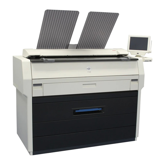
1. 3 Features (1) The KIP 7100 is a single footprint Multi-Function Printer which can copy, scan and print. Advanced drivers and comprehensive print utilities make the KIP 7100 an advanced, easy to use system. (some functions may be optional) (2) KIP HDP technology generates no waste toner. - Page 11
1. 4 Specifications 1. 4. 1 General Subject Specification Model KIP 7100 Configuration Console Power consumption 1,440W (US model) (Maximum) 1,680W (EU / Asia model) (scanner / controller included) Power consumption 30W or less (Low power mode) Acoustic noise Idling Max. - Page 12
1. 4. 2 Printer part Subject Specification Printing method LED Array Electro photography Photoreceptor Organic Photoconductive Drum Print speed 80mm per second (Inch) 3.4ppm/E 5.8ppm/D Landscape (Metric) 3.3ppm/A0 5.6ppm/A1 Landscape Print head LED Array Resolution of print head 600dpi x 600dpi Print width Maximum 914mm / 36”… - Page 13
Subject Specification Media source 2 Roll Decks Manual Feeder (single cut sheet) Paper Tray (multiple cut sheet, option) Media (Recommended Media) US model: Bond 64g/m to 80g/m , US Bond (PB-20) Vellum US Vellum (XV-20) Film 4MIL (PF-4DDME) Europe/Asia model: Plain Paper 64g/m to 80g/m… - Page 14
1. 4. 3 Scanner part Subject Specification Scanning method Contact Image Sensor (CIS) (5 pieces of A4 sized CIS) Light source LED (R/G/B) Setting of original Face up Starting point of scan Center Scan width Max: 914.4mm / 36” Min : 279.4mm Scan length Max:… -
Page 15: Front View
1. 5. 1 Front view Name Function Main Switch You can turn on/off the KIP 7100. Original Guides Feed the original under the Scanner Unit along the Original Guides. User Interface This is a Touch Screen, and many kinds of user operation are available.
-
Page 16: Rear View
Open the Exit Cover when you remove the paper misfed inside the Fuser Unit. LAN Port Connect the LAN Cable to connect the KIP 7100 to the network. (Do not connect a telephone line) Dehumidify Heater Switch Turn on the Dehumidify Heater with this switch when you (Optional in the US) would like to dry the paper in the humid season.
- Page 17
1. 6 Specifications for the Scan Original A scan original must satisfy the following specifications. Thickness 0.05mm to 1.6mm Width 279.4mm to 914.4mm Length 210mm to 6,000mm (If an original is thicker than 0.65mm, its image quality is not guaranteed even it is transported.) Do not scan the following kinds of originals. - Page 18
Not square K I P K I P Metal or fabric material Metal Fabric K I P K I P Rough surface (Carbon paper for example) Rough surface Clipped or stapled Clipped Stapled K I P K I P 1-12 Chapter 1 Before Use… - Page 19
The following kinds of originals can be read with using a carrier sheet. Image quality or the reliability of paper feeding for them is not guaranteed. Patched Punched 1-13 Chapter 1 Before Use… -
Page 20: Papers Not Available To Use
1. 7 Specifications for the Printing Paper 1. 7. 1 Papers not available to use Do not use the following kinds of printing paper. Doing so may damage the print engine. Excessively curled (a diameter of 50 mm or less) Folded Creased Torn…
-
Page 21: Keeping The Paper In The Custody
Pre-printed Extremely slippery Extremely sticky Extremely thin and soft OHP Film CAUTION Do not use the paper with staple, or do not use such conductive paper as aluminium foil and carbon paper. The above may result in a danger of fire NOTE (1) Print image may become light if printed on a rough surface of the paper.
-
Page 22: Treatment Against Environmental Condition
High NOTE (1) KIP 7100 is equipped with the Dehumidify Heater (optional for the US). Using it in high humidity environment (65% or higher) is recommended. Refer to [2.9 Dehumidifying Roll Paper]. (2) “Void of image” and “crease of paper” will occur in case of extremely high or low humidity.
-
Page 23: Table Of Contents
Chapter 2 Basic Operation page 2. 1 Turning on KIP 7100 2- 2 2. 2 Turning off KIP 7100 2- 4 2. 3 Replacing Roll Media 2- 5 2. 4 Replacing Toner Cartridge 2-11 2. 5 Cut Sheet Media 2-15 2.
-
Page 24: Turning On Kip 7100
In Europe : 220-240V plus 6% or minus 10%, 50/60Hz and 10A 2. Press “ | ” side the Power Switch on the right side of the printer to turn on the KIP 7100. Power Switch Press “ | “ side.
- Page 25
Ready Indicator The UI screen may vary depending on your system configuration. (Shown with available options) 4. When Ready Indicator stops flashing, the KIP 7100 is ready for operation. NOTE It is impossible to make any prints while Ready Indicator is flashing in orange. -
Page 26: Turning Off Kip 7100
” side. CAUTION The KIP 7100 print engine and UI appear to be shut down when you turn off KIP 7100. However, the controller PC embedded inside the KIP 7100 is still operating and will shutdown in approximately two minutes after Power Switch operation.
-
Page 27: Replacing Roll Media
2. 3 Replacing Roll Media NOTE (1) A paper mis-feed tends to occur just before out of a roll paper. (2) A tracing roll paper is recommended to be loaded to Roll Deck 1 (front). Reference This section describes how to install a roll media to Roll Deck 1. The same procedure is applied to Roll Deck 2, unless otherwise noted.
- Page 28
3. Raise the green lever (4) on Flange (2). Remove both Flanges (4) from the roll core (3). 3. Move a right Slide Guide (5) to match your roll media’s width. The right and left Side Guides will automatically move together. Width markings Chapter 2 Basic Operation… - Page 29
4. Insert each Flange (2) into both ends of the roll media core to be installed. NOTE (1) Fully insert Flange into the roll media core so that the inside rim of Flange evenly touches the side face of the roll media. Inside Rim Inside Rim Correct: Fully inserted… - Page 30
6. Lift the roll media by holding both Flanges. Lower Flanges onto Slide Guides (5) in Roll Deck. NOTE (1) Be careful of the winding direction of the roll media. Rear: Deck back Rear: Deck back Front: to media path Front: to media path Correct: Edge comes from bottom Wrong: Edge comes from top… - Page 31
7. Insert the leading edge of the roll media under Guide Plate (8) until it touches the feeding roller. Rotate Feed Knob (9) clockwise so that the feeding rollers catch the leading edge. NOTE Use the rear Feed Knob (10) for Roll Deck 2. 8. - Page 32
9. Slide the green Cutter Knob (12) fully from one side to the other to make a new straight edge. Remove the cut portion. NOTE Completely slide Cutter Knob (12) until it stops at either end. Not doing so may cause a paper jam. Correct Wrong 10. -
Page 33: Replacing Toner Cartridge
2. 4 Replacing Toner Cartridge 1. Open the Toner Hatch (1). 2. Slide the green Lever (2) to the right to unlock the Toner Cartridge. (Lever (2) is held automatically.) NOTE Be sure to unlock the Toner Cartridge by releasing the green Lever (2). Correct: disengaged Wrong: not disengaged 2-11…
- Page 34
3. Pressing down the Cartridge Lock Lever (3), turn the body (4) of cartridge to the arrow direction until it stops. (You can close the toner supply hole of the cartridge firmly by this) NOTE The toner may drop from the toner supply hole, and it may scattered into the machine or on the floor if you remove the Toner Cartridge without closing the toner supply hole (5). - Page 35
5. Shake the new Toner Cartridge several times left and right to make the toner smooth. 6. Pressing down the Cartridge Lock Lever (3), fit the pin (6) on the left side of the cartridge to the groove (7) on the machine side. NOTE Please confirm that the Cartridge Lock Lever (3) firmly locks the Toner Cartridge at the correct position. - Page 36
7. Turn the body (4) of the cartridge in one revolution to the arrow direction to open the toner supply hole. Confirm that the projection (8) if fitted into the notch (9). NOTE It is not necessary to lock the cartridge with the Lever (2). -
Page 37: Cut Sheet Media
2. 5 Cut Sheet Media 1. Open the Bypass Feeder (1). 2. There are several size markings on the table of Bypass Feeder which indicate possible feed positions. Place the cut sheet paper on the table between its concerning size markings then insert it into the Bypass Feeder.
-
Page 38: Copying
When the leading edge touches the original feeding roller, the machine automatically carries and sets the original at the proper position. 3. The KIP 7100 will start the copy process. NOTE The scanner unit does not accept originals automatically during Sleep Mode. Tap on the UI screen and then insert an original.
- Page 39
The KIP 7100 has the ability to eject prints / copies to the printer’s top tray (standard) / rear stacking equipment (option). For the top tray, the printer will inform you of “Tray Full” on exceeding capacity of stacking. If the UI screen shows “Tray Full”, remove all the prints on the top tray. -
Page 40: Emergency Stop Of Scan Or Copy
2. 7 Emergency Stop of Scan or Copy 1. If necessary, press the Emergency Stop Button (1) on the Scanner Unit to immediately stop the original while making a copy or scan. Pressing the button stops the current reading a document immediately. The current printing is stopped as well and is ejected.
-
Page 41: Canceling Sleep Mode
NOTE (1) It may take time for the machine to get ready. (2) Tapping on the UI screen can cancel the screensaver but the KIP 7100 needs to recover temperature on Fuser Unit. It may need another waiting time to start warming up for printing.
-
Page 42: Dehumidifying Roll Media
Loss of image If the media is humidified; If the KIP 7100 is installed in such a condition, it is recommended to use the optional embedded “Dehumidify Heater”. Turn on the Dehumidify Heater if the room air has too much humidity (65% or higher) to prevent the above kinds of print defect.
- Page 43
Chapter 3 Error Correction page 3. 1 Mis-feed Error 3- 2 3. 1. 1 Deck Jam / Feeding Jam 3- 2 3. 1. 2 Manual Jam 3- 5 3. 1. 3 Reg. Jam / Internal Jam 3- 6 3. 1. 4 Fuser Jam 3- 7 3. -
Page 44: Mis-Feed Error
3. 1 Mis-feed Error NOTE (1) Be careful not to get paper cuts on your hand. (2) It is recommended to take off your ring, bracelet or watch when removing a mis-feed media. 3. 1. 1 Deck Jam / Feeding Jam Either of “Deck is jam”…
- Page 45
2. Insert the leading edge of the roll media under Guide Plate (2) until it touches the feeding roller. Rotate Feed Knob (3) clockwise so that the feeding rollers catch the leading edge. NOTE (1) The leading edge should be trimmed with a cutter in case of an extreme crease. - Page 46
4. Slide the green Cutter Knob (6) fully from one side to the other to make a new straight edge. Remove the cut portion. NOTE Completely slide Cutter Knob (6) until it stops at either end. Not doing so may cause a paper jam. Correct Wrong 5. -
Page 47: Manual Jam
3. 1. 2 Manual Jam 1. Remove Print Trays (1). 2. Pull up the Engine Unit Open Levers (2) to open the Engine Unit. 3. Remove the mis-fed paper pulling frontward. mis-fed media 4. Gently close the Engine Unit. NOTE (1) Be sure to close the Engine Unit firmly until it locks at the correct position.
-
Page 48: Reg. Jam / Internal Jam
3. 1. 3 Reg. Jam / Internal Jam 1. Remove Print Trays (1). 2. Pull up the Engine Unit Open Levers (1) to open the Engine Unit. 3. Remove the mis-fed paper. mis-fed media 4. Gently close the Engine Unit. NOTE Be sure to close the Engine Unit firmly until it locks at the correct position.
-
Page 49: Fuser Jam
3. 1. 4 Fuser Jam 1. Remove Print Trays (1). 2. Pull up the Engine Unit Open Levers (2) to open the Engine Unit. 3. Remove the mis-fed paper. If the mis-fed paper cannot be seen or removed, leave the media and go to the next step. mis-fed media 4.
- Page 50
5. Pull and remove the jammed print to the rear. If you remove the print at this time, just close the Exit Cover. If the print cannot be removed, go to the next step. jammed print NOTE If removed a mis-fed paper inside the Exit Cover, scattered toner can be adhered to the next print. - Page 51
7. Close Fuser Door (5) and Exit Cover (3). 8. Gently close the Engine Unit. NOTE Be sure to close the Engine Unit firmly until it locks at the correct position. 9. Replace Print Trays in the original position. Chapter 3 Error Correction… -
Page 52: Stack Jam
3. 1. 5 Stack Jam 1. Remove print(s) on Print Trays. 2. Remove Print Trays (1). 3. Pull up the Engine Unit Open Levers (2) to open the Engine Unit. 4. Pull and remove the jammed print to the top. If you remove the print at this time, just close the Engine Unit.
-
Page 53: Original Jam
3. 1. 6 Original Jam 1. Open the Scanner Unit pulling up the Levers (1), and then remove the original. 2. Gently press Scanner Unit down and firmly close it. NOTE Press down Scanner Unit on both the sides to close it. Do not close it by pressing only one side down.
-
Page 54: Other Operator Call Error
3. 2 Other Operator Call Error 3. 2. 1 Roll Replacement When the printer is running out of an loaded roll media, the UI Screen will display “Roll Replacement” sign. If there is no suitable roll media required for the current print job, the UI Screen will display “Roll Replacement”…
- Page 55
1. Turn off KIP 7100, and turn it on after an interval of 30 seconds or more. 2. If the same error code appears, turn off KIP 7100, and then unplug the printer from the wall outlet after an interval of two minutes for shutdown. - Page 56
Chapter 4 Maintenance page 4. 1 Cleaning 4- 2 4. 1. 1 Scanner Unit 4- 2 4. 1. 2 Touch Screen 4- 4 Chapter 4 Maintenance… - Page 57
It is recommended to clean each Scan Glass, Feeding Rollers and Guide Plates as the scan/copy image may become defective if these parts are dirty. 1. Turn off KIP 7100. 2. Press the levers (1) up to unlock the Scanner Unit. Open the Scanner Unit. - Page 58
4. Wipe the Feed Rollers (4), Press Rollers (5) and the inside surface with a soft dry cloth. 5. Gently press Scanner Unit down and firmly close it. NOTE Press down Scanner Unit on both side to close it. Do not close it by pressing only one side down. Chapter 4 Maintenance… - Page 59
4. 1. 2 Touch Screen 1. Wipe the Touch Screen with a dry cloth. NOTE Do not use water, alcohol, organic solvent and glass cleaner for the cleaning. Chapter 4 Maintenance…
- Manuals
- Brands
- KIP Manuals
- All in One Printer
- KIP 7100
- User manual
-
Contents
-
Table of Contents
-
Bookmarks
Quick Links
KIP 7100 ‐ User Manual
Version A1
Related Manuals for KIP 7100
Summary of Contents for KIP 7100
- Page 1
KIP 7100 ‐ User Manual Version A1… - Page 2
Thank you for purchasing the Multi-Function Printer KIP 7100. This Hardware Operation Guide contains functional and operational explanations for the KIP 7100. Please read this Hardware Operation Guide carefully before using the printer. Please keep this Hardware Operation Guide for future reference. -
Page 3: Safety Warnings
Safety Warnings The following warnings are very important in order to safely use this product. These notes are important in preventing danger to the operator or operation of the printer. The following symbols are found throughout the USER’S Manual and have the following meaning: WARNING This WARNING mark means that there is a possibility of death or serious injury if you ignore or do not follow the said instruction.
- Page 4
WARNING Ground the product with a correct ground source or you may be electrically shocked. 1. The Power source should be as follows: In U.S.A. : 120V plus/minus10%, 50/60Hz, 15A or higher In Europe : 220-240V plus6% or minus10%, 50/60Hz, 10A or higher 2. - Page 5
CAUTION Do not install the printer in a humidified room or a dusty room. Also, do not install the printer on an unstable floor as injuries may occur. 1. Unplug the printer before you move it. The power cord may be damaged and it may result in a fire or electric shock. - Page 6
POWER CORD INSTRUCTION The installation of (or exchange to) a power plug which fits in the wall outlet of the installation location shall be conducted in accordance with the following: WARNING Select a power plug which meets the following criteria; — The plug has a voltage and current rating appropriate for the product’s rating marked on its name plate. - Page 7
Chapter 1 Before Use page 1. 1 Installation Requirements 1- 2 1. 2 Originals Prohibited from Duplication 1- 3 1. 3 Features 1- 4 1. 4 Specifications 1- 5 1. 4. 1 General 1- 5 1. 4. 2 Printer part 1- 6 1. - Page 8
The equipment must be leveled and the floor strength must be ample to sustain the weight of the equipment. 30cm/12” or larger (Rear) KIP 7100 * L + R = 35cm/14” or larger (R must be larger than L) (L = 5cm/2” or larger… - Page 9
1. 2 Originals Prohibited from Duplication It is not necessarily allowed to copy every kind of original. You may be punished by the law if only you possess the copy of some kind of original. We recommend you to consider enough before you copy such original. [Originals prohibited from copying by the law] 1. - Page 10
1. 3 Features (1) The KIP 7100 is a single footprint Multi-Function Printer which can copy, scan and print. Advanced drivers and comprehensive print utilities make the KIP 7100 an advanced, easy to use system. (some functions may be optional) (2) KIP HDP technology generates no waste toner. - Page 11
1. 4 Specifications 1. 4. 1 General Subject Specification Model KIP 7100 Configuration Console Power consumption 1,440W (US model) (Maximum) 1,680W (EU / Asia model) (scanner / controller included) Power consumption 30W or less (Low power mode) Acoustic noise Idling Max. - Page 12
1. 4. 2 Printer part Subject Specification Printing method LED Array Electro photography Photoreceptor Organic Photoconductive Drum Print speed 80mm per second (Inch) 3.4ppm/E 5.8ppm/D Landscape (Metric) 3.3ppm/A0 5.6ppm/A1 Landscape Print head LED Array Resolution of print head 600dpi x 600dpi Print width Maximum 914mm / 36”… - Page 13
Subject Specification Media source 2 Roll Decks Manual Feeder (single cut sheet) Paper Tray (multiple cut sheet, option) Media (Recommended Media) US model: Bond 64g/m to 80g/m , US Bond (PB-20) Vellum US Vellum (XV-20) Film 4MIL (PF-4DDME) Europe/Asia model: Plain Paper 64g/m to 80g/m… - Page 14
1. 4. 3 Scanner part Subject Specification Scanning method Contact Image Sensor (CIS) (5 pieces of A4 sized CIS) Light source LED (R/G/B) Setting of original Face up Starting point of scan Center Scan width Max: 914.4mm / 36” Min : 279.4mm Scan length Max:… -
Page 15: Front View
1. 5. 1 Front view Name Function Main Switch You can turn on/off the KIP 7100. Original Guides Feed the original under the Scanner Unit along the Original Guides. User Interface This is a Touch Screen, and many kinds of user operation are available.
-
Page 16: Rear View
Open the Exit Cover when you remove the paper misfed inside the Fuser Unit. LAN Port Connect the LAN Cable to connect the KIP 7100 to the network. (Do not connect a telephone line) Dehumidify Heater Switch Turn on the Dehumidify Heater with this switch when you (Optional in the US) would like to dry the paper in the humid season.
- Page 17
1. 6 Specifications for the Scan Original A scan original must satisfy the following specifications. Thickness 0.05mm to 1.6mm Width 279.4mm to 914.4mm Length 210mm to 6,000mm (If an original is thicker than 0.65mm, its image quality is not guaranteed even it is transported.) Do not scan the following kinds of originals. - Page 18
Not square K I P K I P Metal or fabric material Metal Fabric K I P K I P Rough surface (Carbon paper for example) Rough surface Clipped or stapled Clipped Stapled K I P K I P 1-12 Chapter 1 Before Use… - Page 19
The following kinds of originals can be read with using a carrier sheet. Image quality or the reliability of paper feeding for them is not guaranteed. Patched Punched 1-13 Chapter 1 Before Use… -
Page 20: Papers Not Available To Use
1. 7 Specifications for the Printing Paper 1. 7. 1 Papers not available to use Do not use the following kinds of printing paper. Doing so may damage the print engine. Excessively curled (a diameter of 50 mm or less) Folded Creased Torn…
-
Page 21: Keeping The Paper In The Custody
Pre-printed Extremely slippery Extremely sticky Extremely thin and soft OHP Film CAUTION Do not use the paper with staple, or do not use such conductive paper as aluminium foil and carbon paper. The above may result in a danger of fire NOTE (1) Print image may become light if printed on a rough surface of the paper.
-
Page 22: Treatment Against Environmental Condition
High NOTE (1) KIP 7100 is equipped with the Dehumidify Heater (optional for the US). Using it in high humidity environment (65% or higher) is recommended. Refer to [2.9 Dehumidifying Roll Paper]. (2) “Void of image” and “crease of paper” will occur in case of extremely high or low humidity.
-
Page 23: Table Of Contents
Chapter 2 Basic Operation page 2. 1 Turning on KIP 7100 2- 2 2. 2 Turning off KIP 7100 2- 4 2. 3 Replacing Roll Media 2- 5 2. 4 Replacing Toner Cartridge 2-11 2. 5 Cut Sheet Media 2-15 2.
-
Page 24: Turning On Kip 7100
In Europe : 220-240V plus 6% or minus 10%, 50/60Hz and 10A 2. Press “ | ” side the Power Switch on the right side of the printer to turn on the KIP 7100. Power Switch Press “ | “ side.
- Page 25
Ready Indicator The UI screen may vary depending on your system configuration. (Shown with available options) 4. When Ready Indicator stops flashing, the KIP 7100 is ready for operation. NOTE It is impossible to make any prints while Ready Indicator is flashing in orange. -
Page 26: Turning Off Kip 7100
” side. CAUTION The KIP 7100 print engine and UI appear to be shut down when you turn off KIP 7100. However, the controller PC embedded inside the KIP 7100 is still operating and will shutdown in approximately two minutes after Power Switch operation.
-
Page 27: Replacing Roll Media
2. 3 Replacing Roll Media NOTE (1) A paper mis-feed tends to occur just before out of a roll paper. (2) A tracing roll paper is recommended to be loaded to Roll Deck 1 (front). Reference This section describes how to install a roll media to Roll Deck 1. The same procedure is applied to Roll Deck 2, unless otherwise noted.
- Page 28
3. Raise the green lever (4) on Flange (2). Remove both Flanges (4) from the roll core (3). 3. Move a right Slide Guide (5) to match your roll media’s width. The right and left Side Guides will automatically move together. Width markings Chapter 2 Basic Operation… - Page 29
4. Insert each Flange (2) into both ends of the roll media core to be installed. NOTE (1) Fully insert Flange into the roll media core so that the inside rim of Flange evenly touches the side face of the roll media. Inside Rim Inside Rim Correct: Fully inserted… - Page 30
6. Lift the roll media by holding both Flanges. Lower Flanges onto Slide Guides (5) in Roll Deck. NOTE (1) Be careful of the winding direction of the roll media. Rear: Deck back Rear: Deck back Front: to media path Front: to media path Correct: Edge comes from bottom Wrong: Edge comes from top… - Page 31
7. Insert the leading edge of the roll media under Guide Plate (8) until it touches the feeding roller. Rotate Feed Knob (9) clockwise so that the feeding rollers catch the leading edge. NOTE Use the rear Feed Knob (10) for Roll Deck 2. 8. - Page 32
9. Slide the green Cutter Knob (12) fully from one side to the other to make a new straight edge. Remove the cut portion. NOTE Completely slide Cutter Knob (12) until it stops at either end. Not doing so may cause a paper jam. Correct Wrong 10. -
Page 33: Replacing Toner Cartridge
2. 4 Replacing Toner Cartridge 1. Open the Toner Hatch (1). 2. Slide the green Lever (2) to the right to unlock the Toner Cartridge. (Lever (2) is held automatically.) NOTE Be sure to unlock the Toner Cartridge by releasing the green Lever (2). Correct: disengaged Wrong: not disengaged 2-11…
- Page 34
3. Pressing down the Cartridge Lock Lever (3), turn the body (4) of cartridge to the arrow direction until it stops. (You can close the toner supply hole of the cartridge firmly by this) NOTE The toner may drop from the toner supply hole, and it may scattered into the machine or on the floor if you remove the Toner Cartridge without closing the toner supply hole (5). - Page 35
5. Shake the new Toner Cartridge several times left and right to make the toner smooth. 6. Pressing down the Cartridge Lock Lever (3), fit the pin (6) on the left side of the cartridge to the groove (7) on the machine side. NOTE Please confirm that the Cartridge Lock Lever (3) firmly locks the Toner Cartridge at the correct position. - Page 36
7. Turn the body (4) of the cartridge in one revolution to the arrow direction to open the toner supply hole. Confirm that the projection (8) if fitted into the notch (9). NOTE It is not necessary to lock the cartridge with the Lever (2). -
Page 37: Cut Sheet Media
2. 5 Cut Sheet Media 1. Open the Bypass Feeder (1). 2. There are several size markings on the table of Bypass Feeder which indicate possible feed positions. Place the cut sheet paper on the table between its concerning size markings then insert it into the Bypass Feeder.
-
Page 38: Copying
When the leading edge touches the original feeding roller, the machine automatically carries and sets the original at the proper position. 3. The KIP 7100 will start the copy process. NOTE The scanner unit does not accept originals automatically during Sleep Mode. Tap on the UI screen and then insert an original.
- Page 39
The KIP 7100 has the ability to eject prints / copies to the printer’s top tray (standard) / rear stacking equipment (option). For the top tray, the printer will inform you of “Tray Full” on exceeding capacity of stacking. If the UI screen shows “Tray Full”, remove all the prints on the top tray. -
Page 40: Emergency Stop Of Scan Or Copy
2. 7 Emergency Stop of Scan or Copy 1. If necessary, press the Emergency Stop Button (1) on the Scanner Unit to immediately stop the original while making a copy or scan. Pressing the button stops the current reading a document immediately. The current printing is stopped as well and is ejected.
-
Page 41: Canceling Sleep Mode
NOTE (1) It may take time for the machine to get ready. (2) Tapping on the UI screen can cancel the screensaver but the KIP 7100 needs to recover temperature on Fuser Unit. It may need another waiting time to start warming up for printing.
-
Page 42: Dehumidifying Roll Media
Loss of image If the media is humidified; If the KIP 7100 is installed in such a condition, it is recommended to use the optional embedded “Dehumidify Heater”. Turn on the Dehumidify Heater if the room air has too much humidity (65% or higher) to prevent the above kinds of print defect.
- Page 43
Chapter 3 Error Correction page 3. 1 Mis-feed Error 3- 2 3. 1. 1 Deck Jam / Feeding Jam 3- 2 3. 1. 2 Manual Jam 3- 5 3. 1. 3 Reg. Jam / Internal Jam 3- 6 3. 1. 4 Fuser Jam 3- 7 3. -
Page 44: Mis-Feed Error
3. 1 Mis-feed Error NOTE (1) Be careful not to get paper cuts on your hand. (2) It is recommended to take off your ring, bracelet or watch when removing a mis-feed media. 3. 1. 1 Deck Jam / Feeding Jam Either of “Deck is jam”…
- Page 45
2. Insert the leading edge of the roll media under Guide Plate (2) until it touches the feeding roller. Rotate Feed Knob (3) clockwise so that the feeding rollers catch the leading edge. NOTE (1) The leading edge should be trimmed with a cutter in case of an extreme crease. - Page 46
4. Slide the green Cutter Knob (6) fully from one side to the other to make a new straight edge. Remove the cut portion. NOTE Completely slide Cutter Knob (6) until it stops at either end. Not doing so may cause a paper jam. Correct Wrong 5. -
Page 47: Manual Jam
3. 1. 2 Manual Jam 1. Remove Print Trays (1). 2. Pull up the Engine Unit Open Levers (2) to open the Engine Unit. 3. Remove the mis-fed paper pulling frontward. mis-fed media 4. Gently close the Engine Unit. NOTE (1) Be sure to close the Engine Unit firmly until it locks at the correct position.
-
Page 48: Reg. Jam / Internal Jam
3. 1. 3 Reg. Jam / Internal Jam 1. Remove Print Trays (1). 2. Pull up the Engine Unit Open Levers (1) to open the Engine Unit. 3. Remove the mis-fed paper. mis-fed media 4. Gently close the Engine Unit. NOTE Be sure to close the Engine Unit firmly until it locks at the correct position.
-
Page 49: Fuser Jam
3. 1. 4 Fuser Jam 1. Remove Print Trays (1). 2. Pull up the Engine Unit Open Levers (2) to open the Engine Unit. 3. Remove the mis-fed paper. If the mis-fed paper cannot be seen or removed, leave the media and go to the next step. mis-fed media 4.
- Page 50
5. Pull and remove the jammed print to the rear. If you remove the print at this time, just close the Exit Cover. If the print cannot be removed, go to the next step. jammed print NOTE If removed a mis-fed paper inside the Exit Cover, scattered toner can be adhered to the next print. - Page 51
7. Close Fuser Door (5) and Exit Cover (3). 8. Gently close the Engine Unit. NOTE Be sure to close the Engine Unit firmly until it locks at the correct position. 9. Replace Print Trays in the original position. Chapter 3 Error Correction… -
Page 52: Stack Jam
3. 1. 5 Stack Jam 1. Remove print(s) on Print Trays. 2. Remove Print Trays (1). 3. Pull up the Engine Unit Open Levers (2) to open the Engine Unit. 4. Pull and remove the jammed print to the top. If you remove the print at this time, just close the Engine Unit.
-
Page 53: Original Jam
3. 1. 6 Original Jam 1. Open the Scanner Unit pulling up the Levers (1), and then remove the original. 2. Gently press Scanner Unit down and firmly close it. NOTE Press down Scanner Unit on both the sides to close it. Do not close it by pressing only one side down.
-
Page 54: Other Operator Call Error
3. 2 Other Operator Call Error 3. 2. 1 Roll Replacement When the printer is running out of an loaded roll media, the UI Screen will display “Roll Replacement” sign. If there is no suitable roll media required for the current print job, the UI Screen will display “Roll Replacement”…
- Page 55
1. Turn off KIP 7100, and turn it on after an interval of 30 seconds or more. 2. If the same error code appears, turn off KIP 7100, and then unplug the printer from the wall outlet after an interval of two minutes for shutdown. - Page 56
Chapter 4 Maintenance page 4. 1 Cleaning 4- 2 4. 1. 1 Scanner Unit 4- 2 4. 1. 2 Touch Screen 4- 4 Chapter 4 Maintenance… - Page 57
It is recommended to clean each Scan Glass, Feeding Rollers and Guide Plates as the scan/copy image may become defective if these parts are dirty. 1. Turn off KIP 7100. 2. Press the levers (1) up to unlock the Scanner Unit. Open the Scanner Unit. - Page 58
4. Wipe the Feed Rollers (4), Press Rollers (5) and the inside surface with a soft dry cloth. 5. Gently press Scanner Unit down and firmly close it. NOTE Press down Scanner Unit on both side to close it. Do not close it by pressing only one side down. Chapter 4 Maintenance… - Page 59
4. 1. 2 Touch Screen 1. Wipe the Touch Screen with a dry cloth. NOTE Do not use water, alcohol, organic solvent and glass cleaner for the cleaning. Chapter 4 Maintenance…

KIP PrintNET
This information is solely for use of KIP Personnel and KIP Authorized Dealers. No part of this publication may be copied,
reproduced or distributed in any form without express written permission from KIP America, Inc. 2011 KIP America, Inc.
— 5 —
NO.
NAME
FUNCTION
1
Administration
Administrator Functions (when logged on as Admin)
2
Printer Configuration
Printer Configuration Settings
3
IPS Mailboxes
IPS Mailbox Management / Image Download
4
Printer Queue Management
To manage the printer job queue
Note
Color Options
When connected to a KIP Color system allows the management
of the color option.
5
Job History
Recall Printed Jobs from historical queue (if enabled)
6
Information / Help
Operator Guides / IPS Client Software Downloads
7
New Job
Create a New Print Job
8
Add Files
Add Files From Local PC or Network Resource
9
Job Defaults
Configure Job Default Parameters
10
Load Job
Load Saved Print Job With All Printing Parameters
11
Save Job
Save Current Print Job with All Printing Parameters
12
HPGL Pen Table Settings
Manage HPGL Pen Table Settings
13
Stamp Settings
Create / Modify Digital Image Stamps
14
Recall Last Job
Recall Previously Printed Job / Resubmit Print Job
15
Force Size Settings
Select or create a force size setting
16
Media Type
Select Output Media Type
17
Number of Sets
Set the Output Print Job Number of Sets
18
Job Setup Grid
Display Print Job Images and Print Job Settings
19
Requester
Username Recorded in Unified Accounting Print Log (if enabled)
20
Job Number
Job Number Recorded in Unified Accounting Print Log (if
enabled)
21
Description
Description Recorded in Unified Accounting Print Log (if enabled)
22
Submit Print
Dispatches Print Job to Selected Printer
Note: When connected to a KIP Color System the Color Options selection will appear.
– Compatible Printer model: KIP 7100
– KIP 7100 Error Code List and description errors:
- Code: E-000
- Description: Fuser Temperature Rising Error
- Causes: Fuser Temperature does not reach 50C within 120 seconds after turning on.
- Remedy: Error clearance 1 Have you cleared the fuser error in the Error Clear Mode? Yes Wait until the Fuser Unit is enough cooled down. Then select the Error Clear Mode and clear the concerning error.
Wires 2 Are wires among Lamp (H1, H2), Solid State Relay (SSR1) and Thermistors (TH1 & TH2) connected properly? No Connect them properly.
Lamp (H1, H2) 3 Unplug the machine, and then check the resistance of Lamp (H1, H2) with the multi-meter. Is it 15k ohm or lower? No Replace the Lamp.
Thermistors (TH1 & TH2) 4 Select the Information Mode, and then check the temperature of fuser detected by Thermistors (TH1 & TH2). Item No. : 00 (Fuser temperature 1) 01 (Fuser temperature 2) Is each temperature normal? No Replace the concerning Thermistor.
DC Power Supply (DCP1) or Fuse 5 Confirm that the machine is turned on, and then check the voltage of the orange line (J220-4). Is it 24V? No Replace the DC Power Supply if there is no problem with the wires. Confirm that the machine is turned off, and then check whether or not each Fuse is broken. Is any Fuse broken? Yes Replace the Fuse.
Relay (RY1) 6 Select the Device Operation Mode, and then change the signal of the following signal to “H”. Device Code : 22 (Fuser Relay) And check the resistance between the following points. Between RY1-2 and RY1-4 Between RY1-6 and RY1-8 Is the each resistance almost 0 ohm? No Replace the Relay.
Solid State Relay (SSR1) 7 Select the Device Operation Mode, and then change the signal of the following signals to “H”. Device Code : 22 (Fuser Relay) 21 (Fuser Lamp 1) Then check the voltage between J105-1 and J105-2. Is it 0V? Yes Replace the Solid State Relay No Replace the PW12420 PCB.
CAUTION Change the signal of “21” (Fuser Lamp 1) to “L” after checking!
- Code: E-001
- Description: Fuser Over Temperature Error
- Causes: Fuser Temperature reaches over 230C.
- Remedy: Error clearance 1 Have you cleared the fuser error in the Error Clear Mode? (Refer to the page 8-154 as for the Error Clear Mode.) Yes Wait until the Fuser Unit is enough cooled down. Then select the Error Clear Mode and clear the concerning error.
Wires 2 Are wires among Lamp (H1, H2), Solid State Relay (SSR1) and Thermistors (TH1 & TH2) connected properly? No Connect them properly.
Solid State Relay (SSR1) 3 Does the error occur again even if you have cleared it in the Error Clear Mode? Yes Replace the Solid State Relay.
Thermistors (TH1 & TH2) 4 Select the Information Mode, and then check the temperature of fuser detected by Thermistors (TH1 & TH2). Item No. : 00 (Fuser temperature 1) 01 (Fuser temperature 2) Is each temperature normal? No Replace the concerning Thermistor.
- Code: E-002
- Description: Fuser Low Temperature Error
- Causes: 1. Fuser Temperature at the time of turning on was 50 to 100 oC, but it does not rise up to 120 oC within 150 seconds after that. 2. Fuser Temperature at the time of turning on was higher than 100 oC, but it does not rise up to the setting temperature within 330 seconds after that.
- Remedy: Error clearance 1 Have you cleared the fuser error in the Error Clear Mode? Yes Wait until the Fuser Unit is enough cooled down. Then select the Error Clear Mode and clear the concerning error.
Wires 2 Are wires among Lamp (H1, H2), Solid State Relay (SSR1) and Thermistors (TH1 & TH2) connected properly? No Connect them properly.
Lamp (H1, H2) 3 Unplug the machine, and then check the resistance of Lamp (H1, H2) with the multi-meter. Is it 15k ohm or lower? No Replace the Lamp.
Thermistors (TH1 & TH2) 4 Select the Information Mode, and then check the temperature of fuser detected by Thermistors (TH1 & TH2). Item No. : 00 (Fuser temperature 1) 01 (Fuser temperature 2) Is each temperature normal? No Replace the concerning Thermistor.
DC Power Supply (DCP1) or Fuse 5 Confirm that the machine is turned on, and then check the voltage of the orange line (J220-4). Is it 24V? No Replace the DC Power Supply if there is no problem with the wires. Confirm that the machine is turned off, and then check whether or not each Fuse is broken. Is any Fuse broken? Yes Replace the Fuse.
Relay (RY1) 6 Select the Device Operation Mode, and then change the signal of the following signal to “H”. Device Code : 22 (Fuser Relay) And check the resistance between the following points. Between RY1-2 and RY1-4 Between RY1-6 and RY1-8 Is the each resistance almost 0 ohm? No Replace the Relay.
Solid State Relay (SSR1) 7 Select the Device Operation Mode, and then change the signal of the following signals to “H”. Device Code : 22 (Fuser Relay) 21 (Fuser Lamp 1) Then check the voltage between J105-1 and J105-2. Is it 0V? Yes Replace the Solid State Relay No Replace the PW12420 PCB.
CAUTION Change the signal of “21” (Fuser Lamp 1) to “L” after checking!
- Code: E-003
- Description: Fuser Temperature Abnormal Fall Error
- Causes: The difference of temperature between center and side of fuser becomes 50C or more.
- Remedy: Error clearance 1 Have you cleared the fuser error in the Error Clear Mode? Yes Wait until the Fuser Unit is enough cooled down. Then select the Error Clear Mode and clear the concerning error.
Wires 2 Are wires among Lamp (H1, H2), Solid State Relay (SSR1) and Thermistors (TH1 & TH2) connected properly? No Connect them properly.
Thermistors (TH1 & TH2) 3 Select the Information Mode, and then check the temperature of fuser detected by Thermistors (TH1 & TH2). Item No. : 00 (Fuser temperature 1) 01 (Fuser temperature 2) Is each temperature normal? No Replace the concerning Thermistor.
- Code: E-004
- Description: Fuser Temperature Abnormal Fall Error
- Causes: The Lamp of fuser lights (Signal HEAT1 is ‘H’) to heat up the Fuser Roller in the ready condition, but even 1 oC of temperature rise can not be accomplished within 30 seconds.
- Remedy: Error clearance 1 Have you cleared the fuser error in the Error Clear Mode? Yes Wait until the Fuser Unit is enough cooled down. Then select the Error Clear Mode and clear the concerning error.
Wires 2 Are wires among Lamp (H1, H2), Solid State Relay (SSR1) and Thermistors (TH1 & TH2) connected properly? No Connect them properly.
Lamp (H1, H2) 3 Unplug the machine, and then check the resistance of Lamp (H1, H2) with the multi-meter. Is it 15k ohm or lower? No Replace the Lamp.
Thermistors (TH1 & TH2) 4 Select the Information Mode, and then check the temperature of fuser detected by Thermistors (TH1 & TH2). Item No. : 00 (Fuser temperature 1) 01 (Fuser temperature 2) Is each temperature normal? No Replace the concerning Thermistor.
DC Power Supply (DCP1) or Fuse 5 Confirm that the machine is turned on, and then check the voltage of the orange line (J220-4). Is it 24V? No Replace the DC Power Supply if there is no problem with the wires. Confirm that the machine is turned off, and then check whether or not each Fuse is broken. Is any Fuse broken? Yes Replace the Fuse.
Relay (RY1) 6 Select the Device Operation Mode, and then change the signal of the following signal to “H”. Device Code : 22 (Fuser Relay) And check the resistance between the following points. Between RY1-2 and RY1-4 Between RY1-6 and RY1-8 Is the each resistance almost 0 ohm? No Replace the Relay.
Solid State Relay (SSR1) 7 Select the Device Operation Mode, and then change the signal of the following signals to “H”. Device Code : 22 (Fuser Relay) 21 (Fuser Lamp 1) Then check the voltage between J105-1 and J105-2. Is it 0V? Yes Replace the Solid State Relay No Replace the PW12420 PCB.
CAUTION Change the signal of “21” (Fuser Lamp 1) to “L” after checking!
- Code: E-010
- Description: Main Motor Error
- Causes: The Main Motor Output Detection Signal (MAINM_LD) continues to be ‘H’ for 3 seconds or longer when the Main Motor is rotating.
- Remedy: Wires 1 Is the wire between Main Motor and PW12420 PCB connected properly? No Connect it properly.
DC Power Supply (DCP1) or Fuse 2 Confirm that the machine is turned on, and then check the voltage of the orange line (J220-4). Is it 24V? No Replace the DC Power Supply if there is no problem with the wires. Confirm that the machine is turned off, and then check whether or not each Fuse is broken. Is any Fuse broken? Yes Replace the Fuse.
Main Motor (M1) 3 Check the operation of Main Motor in the Device Operation Mode of the Service Mode. Device Code : 00 (Main Motor) Does the Main Motor operate correctly? No Replace the Main Motor.

- Code: E-011
- Description: Fuser Motor Error
- Causes: The Fuser Motor Output Detection Signal (HEATM_LD) continues to be ‘H’ for 3 seconds or longer when the Fuser Motor is rotating.
- Remedy: Wires 1 Is the wire between Fuser Motor and PW12420 PCB connected properly? No Connect it properly.
DC Power Supply (DCP1) or Fuse 2 Confirm that the machine is turned on, and then check the voltage of the orange line (J220-4). Is it 24V? No Replace the DC Power Supply if there is no problem with the wires. Confirm that the machine is turned off, and then check whether or not each Fuse is broken. Is any Fuse broken? Yes Replace the Fuse.
Fuser Motor (M2) 3 Check the operation of Fuser Motor in the Device Operation Mode of the Service Mode. Device Code : 01 (Fuser Motor) Does the Fuser Motor operate correctly? No Replace the Fuser Motor.
- Code: E-012
- Description: Developer Press Motor Error
- Causes: The Developer Press Sensor Signal (PRESS_S) does not change to ‘L’ within 30 seconds after turning on.
- Remedy: Wires 1 Are the wires among Developer Press Sensor (PH4), PW12420 PCB, Driver PCB B (PW6654) and Developer Press Motor (M4) connected properly? No Connect them properly.
Developer Press Motor (M4) Driver PCB B (PW6654) 2 Turn off the machine, and then turn it on again. Is the Developer Unit moved to the Drum side? No Replace the Developer Press Motor or Driver PCB B.
Developer Press Sensor (PH4) 3 Select the Signal Code “104” (Developer Press Sensor) in the Signal Status Mode, and then turn on the machine again. Does the status change from “H” to “L” after turning on? No Replace the Developer Press Sensor.
Fuse 4 Does the fuse (F3) have a proper conductivity? No Replace the fuse (F3).
- Code: E-020
- Description: Counter Error
- Causes: The Counter Connection Detection Signal (COUNT_OPN) continues to be ‘L’ for 1 second or longer after turning on.
- Remedy: Wires 1 Is the wire between Counter and PW12420 PCB connected properly? No Connect it properly.
DC Power Supply (DCP1) or Fuse 2 Confirm that the machine is turned on, and then check the voltage of the orange line (J220-5). Is it 24V? No Replace the DC Power Supply if there is no problem with the wires. Turn off the machine. Does the fuse (F1) have a proper conductivity? No Replace the fuse (F1).
Counter 3 Check the operation of Counter in the Device Operation Mode of the Service Mode. Device Code : 26 (Counter) Does the Counter operate correctly? No Replace the Counter.
- Code: E-031
- Description: Image Corona Output Error
- Causes: The Image Corona Output Detection Signal (IM_LD) continues to be ‘L’ for 1 second or longer when the Image Corona is ON.
- Remedy: Wires 1 Are wires among Image Corona, HV Power Supply PCB and PW12420 PCB connected properly? No Connect them properly.
Image Corona 2 Is the Image Corona dirty? Yes Clean each Corona Wire, Grid Plate and housing. Is the Corona Wire broken? Yes Replace the Corona Wire.
Cleaning Roller 3 Does the bias terminal plate touch to Cleaning Roller shaft properly? No Remove and reapply conductive grease to Cleaning Roller shaft. Relocate the bias terminal plates properly. Is grease applied enough? No Remove and reapply conductive grease to Cleaning Roller shaft.
Transfer Corona 4 Is the Transfer Corona dirty? Yes Clean each Corona Wire and housing. Is the Corona Wire broken? Yes Replace the Corona Wire.
Separation Corona 5 Is the Separation Corona dirty? Yes Clean each Corona Wire and housing. Is the Corona Wire broken? Yes Replace the Corona Wire.
HV Power Supply 6 Can you fix the problem if you replace the HV Power Supply? Yes OK
- Code: E-032
- Description: Separation Corona Output Error
- Causes: The Separation Corona Output Detection Signal (AC_LD) continues to be ‘L’ for 1 second or longer when the Separation Corona is ON.
- Remedy: Wires 1 Are wires among Image Corona, HV Power Supply PCB and PW12420 PCB connected properly? No Connect them properly.
Image Corona 2 Is the Image Corona dirty? Yes Clean each Corona Wire, Grid Plate and housing. Is the Corona Wire broken? Yes Replace the Corona Wire.
Cleaning Roller 3 Does the bias terminal plate touch to Cleaning Roller shaft properly? No Remove and reapply conductive grease to Cleaning Roller shaft. Relocate the bias terminal plates properly. Is grease applied enough? No Remove and reapply conductive grease to Cleaning Roller shaft.
Transfer Corona 4 Is the Transfer Corona dirty? Yes Clean each Corona Wire and housing. Is the Corona Wire broken? Yes Replace the Corona Wire.
Separation Corona 5 Is the Separation Corona dirty? Yes Clean each Corona Wire and housing. Is the Corona Wire broken? Yes Replace the Corona Wire.
HV Power Supply 6 Can you fix the problem if you replace the HV Power Supply? Yes OK
- Code: E-033
- Description: Transfer Corona Output Error
- Causes: The Transfer Corona Output Detection Signal (TR_LD) continues to be ‘L’ for 1 second or longer when the Transfer Corona is ON.
- Remedy: Wires 1 Are wires among Image Corona, HV Power Supply PCB and PW12420 PCB connected properly? No Connect them properly.
Image Corona 2 Is the Image Corona dirty? Yes Clean each Corona Wire, Grid Plate and housing. Is the Corona Wire broken? Yes Replace the Corona Wire.
Cleaning Roller 3 Does the bias terminal plate touch to Cleaning Roller shaft properly? No Remove and reapply conductive grease to Cleaning Roller shaft. Relocate the bias terminal plates properly. Is grease applied enough? No Remove and reapply conductive grease to Cleaning Roller shaft.
Transfer Corona 4 Is the Transfer Corona dirty? Yes Clean each Corona Wire and housing. Is the Corona Wire broken? Yes Replace the Corona Wire.
Separation Corona 5 Is the Separation Corona dirty? Yes Clean each Corona Wire and housing. Is the Corona Wire broken? Yes Replace the Corona Wire.
HV Power Supply 6 Can you fix the problem if you replace the HV Power Supply? Yes OK
– KIP 7100 Error codes and solution steps to fix:
- Code: E-034
- Description: Bias Output Error
- Causes: Bias Output Detection Signal (BIAS_LD) continues to be ‘L’ for 1 second or longer when a specified bias is supplied to the corresponding Developer Unit components.
- Remedy: Wires 1 Are wires among Developer Unit, HV Power Supply PCB and PW12420 PCB connected properly? No Connect them properly.
Developer Unit 2 Is the toner spill out from the Developer Unit? (Or is there any similar problem?) Yes Clean each Corona Wire, Grid Plate and housing. Is the high voltage of Regulation Roller leaking? (The resistance between the central part of Regulation Roller and the Ground is 5 mega ohm or smaller if leaking.) Yes Replace the Regulation Roller.
HV Power Supply 3 Can you fix the problem if you replace the HV Power Supply? Yes OK
- Code: E-040
- Description: Cutter Error
- Causes: 1. The Cutter Home Sensor Signal (MSCUT_L or MSCUT_R) does not change to ‘H’ within 100 millisecond since the Cutter has started the operation. 2. The Cutter Home Sensor Signal (MSCUT_L or MSCUT_R) does not change to ‘L’ within 1 second since the Cutter has started the operation.
- Remedy: Wires 1 Is the wire between Cutter Unit and PW12420 PCB connected properly? No Connect it properly.
Cutter Home Position Sensors (MS6 & MS7) 2 Check the status of the following signals in the Signal Status Mode of the Service Mode. Signal Code : 094 (Cutter Home Position Right) 095 (Cutter Home Position Left) Is the status “L” when the Cutter is at each home position? No Replace the Cutter Unit.
Developer Press Sensor (PH4) 3 Check the operation of Cutter in the Device Operation Mode of the Service Mode. Device Code : 27 (Cutter Motor 1) 28 (Cutter Motor 2) Does the Cutter operate? No Replace the Cutter Unit.
- Code: E-050
- Description: FPGA Error
- Causes: Initialization of FPGA is failed after turning on.
- Remedy: PW12420 PCB 1 Can you fix the problem if you replace the PW12420 PCB? Yes OK
- Code: E-070
- Description: Developer Unit Set Error
- Causes: 1. The Connector J-253 is not connected. 2. The Switch (MS4) is ‘open’ condition, which detects open/close of Engine Unit or Toner Hatch.
- Remedy: Wires 1 Is the wire between Developer Unit and PW12420 PCB connected properly? No Connect it properly.
Switch (MS4) 2 Is the actuator of Switch correctly pressed down when you close the Engine Unit or Toner Hatch? No Adjust the positions of Switch (or Toner Hatch and Engine Unit).
- Code: E-080
- Description: Density Sensor Error
- Causes: The default output of Density Sensor reaches less than 0.1V or more than 1.3V.
- Remedy: Wires 1 Is the wire between Toner Density Sensor and PW12420 PCB connected properly? No Connect it properly.
Density Sensor (PH11) 2 Can you fix the problem if you replace Density Sensor? No Replace PW12420 with a new one.
- Code: E-081
- Description: Density Sensor Output Error
- Causes: The gap between the default output and the standard output of Density Sensor reaches less than 2V.
- Remedy: Wires 1 Is the wire between Toner Density Sensor and PW12420 PCB connected properly? No Connect it properly.
Density Sensor (PH11) 2 Can you fix the problem if you replace Density Sensor? No Replace PW12420 with a new one.
- Code: J-0101
- Description: Roll 2 Feeding Jam “Delay”
- Causes:
- Remedy: Installation of roll paper 1 Is the roll paper correctly installed to the Roll Deck 2? No Install it correctly.
Roll 2 Set Sensor (PH9) 2 Check the status of Roll 2 Set Sensor in the Signal Status Mode of the Service Mode. Signal Code : 106 (Roll 2 Set Sensor) Is the status “H” when the roll paper is set? No 1. Is there any problem with the Drawer Connector which connects the machine and the Roll Deck. 2. Check if there is any problem with the wire connected to the Roll 2 Set Sensor. 3. Replace the Roll 2 Set Sensor if there is no problem with the wire.
Roll 2 Feed Clutch (CL6) 3 Check the operation of Roll 2 Feed Clutch in the Device Operation Mode of the Service Mode. Device Code : 08 (Roll 2 Feed Clutch) Does the clutch operate when you change the output signal from “L” to “H”? No 1. Check if there is any problem with the wire connected to the Roll 2 Feed Clutch. 2. Replace the Roll 2 Feed Clutch if there is no problem with the wire.
Main Motor (M1) 4 Check the status of Roll 2 Set Sensor in the Signal Status Mode of the Service Mode while making the following operation. (Signal Code : 106) 1. Set the leading edge of roll 2 between feeding rollers. (Leading edge must not pass over the Roll 2 Set Sensor.) 2. Close the Roll Deck. Does the status change from “L” to “H” when the machine is transporting the paper? No 1. Check the driving belts of the Roll Deck. 2. Check if there is any problem with the wire connected to the Main Motor. 3. Replace the Main Motor if there is no problem with the wire. Yes 1. Remove the whole Roll Deck, and then re-install it to the machine correctly.
- Code: J-0102
- Description: Roll 1 Feeding Jam “Delay”
- Causes:
- Remedy: Installation of roll paper 1 Is the roll paper correctly installed to the Roll Deck 2? No Install it correctly.
Roll 1 Set Sensor (PH7) 2 Check the status of Roll 1 Set Sensor in the Signal Status Mode of the Service Mode. Signal Code : 105 (Roll 1 Set Sensor) Is the status “H” when the roll paper is set? No 1. Is there any problem with the Drawer Connector which connects the machine and the Roll Deck. 2. Check if there is any problem with the wire connected to the Roll 1 Set Sensor. 3. Replace the Roll 1 Set Sensor if there is no problem with the wire.
Roll 1 Feed Clutch (CL4) 3 Check the operation of Roll 1 Feed Clutch in the Device Operation Mode of the Service Mode. Device Code : 06 (Roll 1 Feed Clutch) Does the clutch operate when you change the output signal from “L” to “H”? No 1. Check if there is any problem with the wire connected to the Roll 1 Feed Clutch. 2. Replace the Roll 1 Feed Clutch if there is no problem with the wire.
Main Motor (M1) 4 Check the status of Roll 1 Set Sensor in the Signal Status Mode of the Service Mode while making the following operation. (Signal Code : 105) 1. Set the leading edge of roll 1 between feeding rollers. (Leading edge must not pass over the Roll 1 Set Sensor.) 2. Close the Roll Deck. Does the status change from “L” to “H” when the machine is transporting the paper? No 1. Check the driving belts of the Roll Deck. 2. Check if there is any problem with the wire connected to the Main Motor. 3. Replace the Main Motor if there is no problem with the wire. Yes 1. Remove the whole Roll Deck, and then re-install it to the machine correctly.
- Code: J-0103, J-0303
- Description: Feeding Jam “Delay” (J-0103) & “Early” (J-0303)
- Causes:
- Remedy: Mis-feed of paper 1 Does the paper mis-fed occur between Roll 1 Set Sensor and Feed Sensor? Yes Remove the mis-fed paper.
Feed Sensor (PH6) 2 Check the status of Feed Sensor in the Signal Status Mode of the Service Mode. Signal Code : 108 (Feed Sensor) Is the status “L” when the paper is not passing beside the sensor? And is it “H” when the paper is passing beside the sensor? No 1. Is there any problem with the Drawer Connector which connects the machine and the Roll Deck. 2. Check if there is any problem with the wire connected to the Feed Sensor. 3. Replace the Feed Sensor if there is no problem with the wire.
Cutter Home Position Sensor (MS6 & MS7) 3 Check the status of Cutter Home Position Sensors in the Signal Status Mode of the Service Mode. Signal Code : 094 (Cutter Home Position Right) 095 (Cutter Home Position Left) Is the status “H” when the Cutter is at each home position? And is it “L” when the Cutter is not at the home position? No 1. Check if there is any problem with the wire connected to the Cutter Home Position Sensor. 2. Replace the Cutter Home Position Sensors if there is no problem with the wire.
Driving mechanism 4 Check the operation of Feed Clutch in the Device Operation Mode of the Service Mode. Device Code : 10 (Feed Clutch) Also open and close the Roll Deck, and check if the Main Motor rotates correctly. Does each Feed Clutch and Main Motor operate correctly? No Replace the Feed Clutch or Main Motor if it is defective.
- Code: J-0104, J-0204
- Description: Reg. Jam “Delay” (J-0104), “Stay” (J-0204) “Early” (J-0304), “Remained” (J-1004)
- Causes:
- Remedy: Mis-feed of paper 1 Does the paper mis-fed occur around the Registration Roller? Yes Remove the mis-fed paper.
Registration Sensor (PH1) 2 Check the status of Registration Sensor in the Signal Status Mode of the Service Mode. Signal Code : 100 (Registration Sensor) Is the status “L” when the paper is not passing beside the sensor? And is it “H” when the paper is passing beside the sensor? No 1. Check if there is any problem with the wire connected to the Registration Sensor. 2. Replace the Registration Sensor if there is no problem with the wire.
Engine Unit 3 Is the Engine Unit closed firmly until it is locked? (Is the pressure around the Registration Roller correct?) No 1. Close the Engine Unit firmly. 2. Adjust the pressure around the Registration Roller.
Driving mechanism 4 Check the operation of Registration Clutch in the Device Operation Mode of the Service Mode. Device Code : 11 (Registration Clutch) Also open and close the Roll Deck, and check if the Main Motor rotates correctly. Does each Registration Clutch and Main Motor operate correctly? No Replace the Registration Clutch or Main Motor if it is defective.
- Code: J-0106, J-0206
- Description: Internal Jam “Delay” (J-0106), “Stay” (J-0206) “Early” (J-0306), “Remained” (J-1006
- Causes:
- Remedy: Mis-feed of paper 1 Does the paper mis-fed occur around the separation area? Yes Remove the mis-fed paper.
Separation Sensor (PH2) 2 Check the status of Separation Sensor in the Signal Status Mode of the Service Mode. Signal Code : 010 (Separation Sensor) Is the status “L” when the paper is not passing beside the sensor? And is it “H” when the paper is passing beside the sensor? No 1. Check if there is any problem with the wire connected to the Separation Sensor. 2. Replace the Separation Sensor if there is no problem with the wire.
Transfer / Separation Corona 3 Is the Transfer / Separation Corona Unit installed to the machine correctly? Yes Install the Transfer / Separation Corona Unit correctly. Is the Corona Wire broken? Yes Replace the Corona Wire.
HV Power Supply 4 Is the output from the HV Power Supply to the Separation Corona correct? No Replace the HV Power Supply.
- Code: J-0107, J-0207
- Description: Fuser Jam “Delay” (J-0107), “Stay” (J-0207) “Early” (J-0307), “Remained” (J-1007)
- Causes:
- Remedy: Mis-feed of paper 1 Does the paper mis-fed occur around the fuser area? Yes Remove the mis-fed paper.
Exit Sensor (PH3) 2 Check the status of Exit Sensor in the Signal Status Mode of the Service Mode. Signal Code : 011 (Exit Sensor) Is the status “L” when the paper is not passing beside the sensor? And is it “H” when the paper is passing beside the sensor? No 1. Check if there is any problem with the wire connected to the Exit Sensor. 2. Replace the Exit Sensor if there is no problem with the wire.
- Code: J-0304, J-1004
- Description: Reg. Jam “Delay” (J-0104), “Stay” (J-0204) “Early” (J-0304), “Remained” (J-1004)
- Causes:
- Remedy: Mis-feed of paper 1 Does the paper mis-fed occur around the Registration Roller? Yes Remove the mis-fed paper.
Registration Sensor (PH1) 2 Check the status of Registration Sensor in the Signal Status Mode of the Service Mode. Signal Code : 100 (Registration Sensor) Is the status “L” when the paper is not passing beside the sensor? And is it “H” when the paper is passing beside the sensor? No 1. Check if there is any problem with the wire connected to the Registration Sensor. 2. Replace the Registration Sensor if there is no problem with the wire.
Engine Unit 3 Is the Engine Unit closed firmly until it is locked? (Is the pressure around the Registration Roller correct?) No 1. Close the Engine Unit firmly. 2. Adjust the pressure around the Registration Roller.
Driving mechanism 4 Check the operation of Registration Clutch in the Device Operation Mode of the Service Mode. Device Code : 11 (Registration Clutch) Also open and close the Roll Deck, and check if the Main Motor rotates correctly. Does each Registration Clutch and Main Motor operate correctly? No Replace the Registration Clutch or Main Motor if it is defective.
- Code: J-0306, J-1006
- Description: Internal Jam “Delay” (J-0106), “Stay” (J-0206) “Early” (J-0306), “Remained” (J-1006
- Causes:
- Remedy: Mis-feed of paper 1 Does the paper mis-fed occur around the separation area? Yes Remove the mis-fed paper.
Separation Sensor (PH2) 2 Check the status of Separation Sensor in the Signal Status Mode of the Service Mode. Signal Code : 010 (Separation Sensor) Is the status “L” when the paper is not passing beside the sensor? And is it “H” when the paper is passing beside the sensor? No 1. Check if there is any problem with the wire connected to the Separation Sensor. 2. Replace the Separation Sensor if there is no problem with the wire.
Transfer / Separation Corona 3 Is the Transfer / Separation Corona Unit installed to the machine correctly? Yes Install the Transfer / Separation Corona Unit correctly. Is the Corona Wire broken? Yes Replace the Corona Wire.
HV Power Supply 4 Is the output from the HV Power Supply to the Separation Corona correct? No Replace the HV Power Supply.
- Code: J-0307, J-1007
- Description: Fuser Jam “Delay” (J-0107), “Stay” (J-0207) “Early” (J-0307), “Remained” (J-1007)
- Causes:
- Remedy: Mis-feed of paper 1 Does the paper mis-fed occur around the fuser area? Yes Remove the mis-fed paper.
Exit Sensor (PH3) 2 Check the status of Exit Sensor in the Signal Status Mode of the Service Mode. Signal Code : 011 (Exit Sensor) Is the status “L” when the paper is not passing beside the sensor? And is it “H” when the paper is passing beside the sensor? No 1. Check if there is any problem with the wire connected to the Exit Sensor. 2. Replace the Exit Sensor if there is no problem with the wire.
- Code: J-1100
- Description: Paper jam by opening the Roll Deck during printing
- Causes:
- Remedy: Opening the Roll Deck 1 Did you open the Roll Deck before the completion of printing? (Roll paper will be rewound after printing. J-1100 will be indicated if you open the deck at that time.) Yes Wait until the roll paper is completely rewound.
Lock of Roll Deck 2 Is the Roll Deck firmly locked? No Close it firmly.
- Code: J-1200
- Description: Paper jam by opening the Exit Cover during printing
- Causes:
- Remedy: Opening the Exit Cover 1 Did you open the Exit Cover during printing? Yes Do not open it during printing.
- Code: n01
- Description: Deck Open
- Causes:
- Remedy: Roll Deck 1 Is the Roll Deck opened? Yes Close it firmly.
Switch (MS5) 2 Check the status of the following signal in the Signal Status Mode of the Service Mode. Signal Code : 009 (Roll Deck Open) Is the status “L” when the Roll Deck is closed? And is it “H” when the Roll Deck is opened? No 1. Check if there is any problem with the wire connected to the Switch (MS5). 2. Replace the Switch (MS5) if there is no problem with the wire.
- Code: n02
- Description: Deck Jam
- Causes:
- Remedy: Mis-feed of paper 1 Does the paper mis-fed occur in the Roll Deck? Yes Remove the mis-fed paper.
Installation of roll paper 2 Is the roll paper correctly installed to the Roll Deck 2? No Install it correctly.
Roll 1 Set Sensor (PH7) Roll 2 Set Sensor (PH9) 3 Check the status of Roll 1 Set Sensor and Roll 2 Set Sensor in the Signal Status Mode of the Service Mode. Signal Code : 105 (Roll 1 Set Sensor) 106 (Roll 2 Set Sensor) Is the status of each sensor “H” when you set the roll paper? No 1. Is there any problem with the Drawer Connector which connects the machine and the Roll Deck. 2. Check if there is any problem with the wire connected to each sensor. 3. Replace the concerning sensor if there is no problem with the wire.
Roll 1 Feed Clutch (CL4) Roll 2 Feed Clutch (CL6) Roll 1 Back Clutch (CL5) Roll 2 Back Clutch (CL7) 4 Check the operation of the following clutches in the Device Operation Mode of the Service Mode. Device Code : 06 (Roll 1 Feed Clutch) 07 (Roll 1 Back Clutch) 08 (Roll 2 Feed Clutch) 09 (Roll 2 Back Clutch) Does each clutch operate correctly? No 1. Check if there is any problem with the wire connected to each clutch. 2. Replace the concerning clutch if there is no problem with the wire.
Main Motor (M1) 5 Check the status of Roll 1 Set Sensor and Roll 2 Set Sensor in the Signal Status Mode of the Service Mode while making the following operation. Signal Code : 105 (Roll 1 Set Sensor) 106 (Roll 2 Set Sensor) 1. Set the leading edge of each roll paper between the concerning feeding rollers. (Leading edge must not pass over each Roll 1 (2) Set Sensor.) 2. Close the Roll Deck. Does the status change from “L” to “H” when the machine is transporting the paper? No 1. Check the driving belts of the Roll Deck. 2. Check if there is any problem with the wire connected to the Main Motor. 3. Replace the Main Motor if there is no problem with the wire. Yes 1. Remove the whole Roll Deck, and then re-install it to the machine correctly.
- Code: n03
- Description: Manual Set NG
- Causes:
- Remedy: Mis-feed 1 Have you already set the cut sheet paper to the Bypass Feeder before you turned on the machine? Yes Remove the paper.
Manual Set Sensor 2 Check the status of Manual Feed Sensor in the Signal Status Mode of the Service Mode. Signal Code : 008 (Manual Set Sensor) Is the status “L” when the paper is not passing beside the sensor? And is it “H” when the paper is passing beside the sensor? No 1. Check if there is any problem with the wire connected to the Manual Set Sensor. 2. Replace the Manual Set Sensor if there is no problem with the wire.
Registration Sensor 3 Check the status of Registration Sensor in the Signal Status Mode of the Service Mode. Signal Code : 100 (Registration Sensor) Is the status “L” when the paper is not passing beside the sensor? And is it “H” when the paper is passing beside the sensor? No 1. Check if there is any problem with the wire connected to Registration Sensor. 2. Replace the Registration Sensor if there is no problem with the wire.
Engine Unit 4 Is Engine Unit closed firmly? (Is the pressure around Registration Roller correct?) No 1. Close Engine Unit firmly. 2. Adjust the pressure around Registration Roller.
Driving mechanism 5 Check the operation of Registration Clutch in the Device Operation Mode of the Service Mode. Device Code : 11 (Registration Clutch) Open and close Roll Deck and check if Main Motor rotates correctly. Does each Registration Clutch and Main Motor operate correctly? No Replace the Registration Clutch or Main Motor if it is defective.
- Code: n04
- Description: Toner SensorToner Empty
- Causes:
- Remedy: Toner Cartridge 1 Is there enough toner in the Toner Cartridge? No Replace the Toner Cartridge.
Toner Supply Motor (M3) 2 Check the operation of Toner Supply Motor by the following 2 ways. 1. Turn on the machine and check the action of Toner Supply Motor at that time. 2. Enter Factory Adjustment Mode and carry out Sub Mode No.05. Press [ * ] Key when the machine is operating. (Toner Supply Motor rotates during [ * ] Key pressed.) Does Toner Supply Motor operate correctly in both cases? No 1. Check if there is any problem with the wires among Toner Supply Motor, Driver PCB B and PW12420 PCB. 2. Replace the Toner Supply Motor if there is no problem with the wire.
Toner Sensor (TLS1) 3 Confirm that the Toner Sensor is not buried in the toner. Then check the status of Toner Sensor in the Input/Output Mode of the Service Mode. I/O Signal Code : 107 (Toner Sensor) Is the status “H” when the Toner Sensor is covered with the toner? And is it “L” when the sensor is not covered? No Replace the Toner Sensor. Yes Replace the PW12420 PCB.
- Code: n05
- Description: The door opened during the print
- Causes:
- Remedy: feed of paper 1 Is there a paper anywhere in the machine? Yes Open the Exit Cover and the Engine Unit, and then remove the paper. (Cut the paper manually if it has not been cut yet.)
Switch (MS5) 2 Check the status of the following signal in the Signal Status Mode of the Service Mode. Signal Code : 009 (Roll Deck Open) Is the status “L” when the Roll Deck is closed? And is it “H” when the Roll Deck is opened? No 1. Check if there is any problem with the wire connected to the Switch (MS5). 2. Replace the Switch (MS5) if there is no problem with the wire.
Fuse 3 Does the fuse (F2) have a proper conductivity? No Replace the fuse (F2).
- Code: n06
- Description: Abnormal variation in cut length
- Causes:
- Remedy: Sensor (PH12) with encoder
1 Check the status of the following signal in the Signal Status Mode of the Service Mode. Signal Code : 109 (Feed Encoder) Is the status changed “H” and “L” alternately when rotating the encoder by hand? No 1. Check if there is any problem with the wire connected to the Sensor (PH12). 2. Replace the Sensor (PH12) if there is no problem with the wire.
2 Does the encoder rotate smoothly when feeding media by Feed Knob? No Replace the shaft or bracket that supports the encoder.
Contact us to get support with KIP 7100 Error case
Telegram: https://t.me/hyperaktiv
Facebook: https://www.facebook.com/dngnm/
-
Contents
-
Table of Contents
-
Bookmarks
Quick Links
KIP 7100 ‐ User Manual
Version A1
Related Manuals for KIP KIP 7100
Summary of Contents for KIP KIP 7100
-
Page 1
KIP 7100 ‐ User Manual Version A1… -
Page 2
Thank you for purchasing the Multi-Function Printer KIP 7100. This Hardware Operation Guide contains functional and operational explanations for the KIP 7100. Please read this Hardware Operation Guide carefully before using the printer. Please keep this Hardware Operation Guide for future reference. -
Page 3: Safety Warnings
Safety Warnings The following warnings are very important in order to safely use this product. These notes are important in preventing danger to the operator or operation of the printer. The following symbols are found throughout the USER’S Manual and have the following meaning: WARNING This WARNING mark means that there is a possibility of death or serious injury if you ignore or do not follow the said instruction.
-
Page 4
WARNING Ground the product with a correct ground source or you may be electrically shocked. 1. The Power source should be as follows: In U.S.A. : 120V plus/minus10%, 50/60Hz, 15A or higher In Europe : 220-240V plus6% or minus10%, 50/60Hz, 10A or higher 2. -
Page 5
CAUTION Do not install the printer in a humidified room or a dusty room. Also, do not install the printer on an unstable floor as injuries may occur. 1. Unplug the printer before you move it. The power cord may be damaged and it may result in a fire or electric shock. -
Page 6
POWER CORD INSTRUCTION The installation of (or exchange to) a power plug which fits in the wall outlet of the installation location shall be conducted in accordance with the following: WARNING Select a power plug which meets the following criteria; — The plug has a voltage and current rating appropriate for the product’s rating marked on its name plate. -
Page 7
Chapter 1 Before Use page 1. 1 Installation Requirements 1- 2 1. 2 Originals Prohibited from Duplication 1- 3 1. 3 Features 1- 4 1. 4 Specifications 1- 5 1. 4. 1 General 1- 5 1. 4. 2 Printer part 1- 6 1. -
Page 8
The equipment must be leveled and the floor strength must be ample to sustain the weight of the equipment. 30cm/12” or larger (Rear) KIP 7100 * L + R = 35cm/14” or larger (R must be larger than L) (L = 5cm/2” or larger… -
Page 9
1. 2 Originals Prohibited from Duplication It is not necessarily allowed to copy every kind of original. You may be punished by the law if only you possess the copy of some kind of original. We recommend you to consider enough before you copy such original. [Originals prohibited from copying by the law] 1. -
Page 10
1. 3 Features (1) The KIP 7100 is a single footprint Multi-Function Printer which can copy, scan and print. Advanced drivers and comprehensive print utilities make the KIP 7100 an advanced, easy to use system. (some functions may be optional) (2) KIP HDP technology generates no waste toner. -
Page 11
1. 4 Specifications 1. 4. 1 General Subject Specification Model KIP 7100 Configuration Console Power consumption 1,440W (US model) (Maximum) 1,680W (EU / Asia model) (scanner / controller included) Power consumption 30W or less (Low power mode) Acoustic noise Idling Max. -
Page 12: Printer Part
1. 4. 2 Printer part Subject Specification Printing method LED Array Electro photography Photoreceptor Organic Photoconductive Drum Print speed 80mm per second (Inch) 3.4ppm/E 5.8ppm/D Landscape (Metric) 3.3ppm/A0 5.6ppm/A1 Landscape Print head LED Array Resolution of print head 600dpi x 600dpi Print width Maximum 914mm / 36”…
-
Page 13
Subject Specification Media source 2 Roll Decks Manual Feeder (single cut sheet) Paper Tray (multiple cut sheet, option) Media (Recommended Media) US model: Bond 64g/m to 80g/m , US Bond (PB-20) Vellum US Vellum (XV-20) Film 4MIL (PF-4DDME) Europe/Asia model: Plain Paper 64g/m to 80g/m… -
Page 14: Scanner Part
1. 4. 3 Scanner part Subject Specification Scanning method Contact Image Sensor (CIS) (5 pieces of A4 sized CIS) Light source LED (R/G/B) Setting of original Face up Starting point of scan Center Scan width Max: 914.4mm / 36” Min : 279.4mm Scan length Max:…
-
Page 15: Front View
1. 5. 1 Front view Name Function Main Switch You can turn on/off the KIP 7100. Original Guides Feed the original under the Scanner Unit along the Original Guides. User Interface This is a Touch Screen, and many kinds of user operation are available.
-
Page 16: Rear View
Open the Exit Cover when you remove the paper misfed inside the Fuser Unit. LAN Port Connect the LAN Cable to connect the KIP 7100 to the network. (Do not connect a telephone line) Dehumidify Heater Switch Turn on the Dehumidify Heater with this switch when you (Optional in the US) would like to dry the paper in the humid season.
-
Page 17
1. 6 Specifications for the Scan Original A scan original must satisfy the following specifications. Thickness 0.05mm to 1.6mm Width 279.4mm to 914.4mm Length 210mm to 6,000mm (If an original is thicker than 0.65mm, its image quality is not guaranteed even it is transported.) Do not scan the following kinds of originals. -
Page 18
Not square K I P K I P Metal or fabric material Metal Fabric K I P K I P Rough surface (Carbon paper for example) Rough surface Clipped or stapled Clipped Stapled K I P K I P 1-12 Chapter 1 Before Use… -
Page 19
The following kinds of originals can be read with using a carrier sheet. Image quality or the reliability of paper feeding for them is not guaranteed. Patched Punched 1-13 Chapter 1 Before Use… -
Page 20: Papers Not Available To Use
1. 7 Specifications for the Printing Paper 1. 7. 1 Papers not available to use Do not use the following kinds of printing paper. Doing so may damage the print engine. Excessively curled (a diameter of 50 mm or less) Folded Creased Torn…
-
Page 21: Keeping The Paper In The Custody
Pre-printed Extremely slippery Extremely sticky Extremely thin and soft OHP Film CAUTION Do not use the paper with staple, or do not use such conductive paper as aluminium foil and carbon paper. The above may result in a danger of fire NOTE (1) Print image may become light if printed on a rough surface of the paper.
-
Page 22: Treatment Against Environmental Condition
High NOTE (1) KIP 7100 is equipped with the Dehumidify Heater (optional for the US). Using it in high humidity environment (65% or higher) is recommended. Refer to [2.9 Dehumidifying Roll Paper]. (2) “Void of image” and “crease of paper” will occur in case of extremely high or low humidity.
-
Page 23: Table Of Contents
Chapter 2 Basic Operation page 2. 1 Turning on KIP 7100 2- 2 2. 2 Turning off KIP 7100 2- 4 2. 3 Replacing Roll Media 2- 5 2. 4 Replacing Toner Cartridge 2-11 2. 5 Cut Sheet Media 2-15 2.
-
Page 24: Turning On Kip 7100
In Europe : 220-240V plus 6% or minus 10%, 50/60Hz and 10A 2. Press “ | ” side the Power Switch on the right side of the printer to turn on the KIP 7100. Power Switch Press “ | “ side.
-
Page 25
Ready Indicator The UI screen may vary depending on your system configuration. (Shown with available options) 4. When Ready Indicator stops flashing, the KIP 7100 is ready for operation. NOTE It is impossible to make any prints while Ready Indicator is flashing in orange. -
Page 26: Turning Off Kip 7100
” side. CAUTION The KIP 7100 print engine and UI appear to be shut down when you turn off KIP 7100. However, the controller PC embedded inside the KIP 7100 is still operating and will shutdown in approximately two minutes after Power Switch operation.
-
Page 27: Replacing Roll Media
2. 3 Replacing Roll Media NOTE (1) A paper mis-feed tends to occur just before out of a roll paper. (2) A tracing roll paper is recommended to be loaded to Roll Deck 1 (front). Reference This section describes how to install a roll media to Roll Deck 1. The same procedure is applied to Roll Deck 2, unless otherwise noted.
-
Page 28
3. Raise the green lever (4) on Flange (2). Remove both Flanges (4) from the roll core (3). 3. Move a right Slide Guide (5) to match your roll media’s width. The right and left Side Guides will automatically move together. Width markings Chapter 2 Basic Operation… -
Page 29
4. Insert each Flange (2) into both ends of the roll media core to be installed. NOTE (1) Fully insert Flange into the roll media core so that the inside rim of Flange evenly touches the side face of the roll media. Inside Rim Inside Rim Correct: Fully inserted… -
Page 30
6. Lift the roll media by holding both Flanges. Lower Flanges onto Slide Guides (5) in Roll Deck. NOTE (1) Be careful of the winding direction of the roll media. Rear: Deck back Rear: Deck back Front: to media path Front: to media path Correct: Edge comes from bottom Wrong: Edge comes from top… -
Page 31
7. Insert the leading edge of the roll media under Guide Plate (8) until it touches the feeding roller. Rotate Feed Knob (9) clockwise so that the feeding rollers catch the leading edge. NOTE Use the rear Feed Knob (10) for Roll Deck 2. 8. -
Page 32
9. Slide the green Cutter Knob (12) fully from one side to the other to make a new straight edge. Remove the cut portion. NOTE Completely slide Cutter Knob (12) until it stops at either end. Not doing so may cause a paper jam. Correct Wrong 10. -
Page 33: Replacing Toner Cartridge
2. 4 Replacing Toner Cartridge 1. Open the Toner Hatch (1). 2. Slide the green Lever (2) to the right to unlock the Toner Cartridge. (Lever (2) is held automatically.) NOTE Be sure to unlock the Toner Cartridge by releasing the green Lever (2). Correct: disengaged Wrong: not disengaged 2-11…
-
Page 34
3. Pressing down the Cartridge Lock Lever (3), turn the body (4) of cartridge to the arrow direction until it stops. (You can close the toner supply hole of the cartridge firmly by this) NOTE The toner may drop from the toner supply hole, and it may scattered into the machine or on the floor if you remove the Toner Cartridge without closing the toner supply hole (5). -
Page 35
5. Shake the new Toner Cartridge several times left and right to make the toner smooth. 6. Pressing down the Cartridge Lock Lever (3), fit the pin (6) on the left side of the cartridge to the groove (7) on the machine side. NOTE Please confirm that the Cartridge Lock Lever (3) firmly locks the Toner Cartridge at the correct position. -
Page 36
7. Turn the body (4) of the cartridge in one revolution to the arrow direction to open the toner supply hole. Confirm that the projection (8) if fitted into the notch (9). NOTE It is not necessary to lock the cartridge with the Lever (2). -
Page 37: Cut Sheet Media
2. 5 Cut Sheet Media 1. Open the Bypass Feeder (1). 2. There are several size markings on the table of Bypass Feeder which indicate possible feed positions. Place the cut sheet paper on the table between its concerning size markings then insert it into the Bypass Feeder.
-
Page 38: Copying
When the leading edge touches the original feeding roller, the machine automatically carries and sets the original at the proper position. 3. The KIP 7100 will start the copy process. NOTE The scanner unit does not accept originals automatically during Sleep Mode. Tap on the UI screen and then insert an original.
-
Page 39
The KIP 7100 has the ability to eject prints / copies to the printer’s top tray (standard) / rear stacking equipment (option). For the top tray, the printer will inform you of “Tray Full” on exceeding capacity of stacking. If the UI screen shows “Tray Full”, remove all the prints on the top tray. -
Page 40: Emergency Stop Of Scan Or Copy
2. 7 Emergency Stop of Scan or Copy 1. If necessary, press the Emergency Stop Button (1) on the Scanner Unit to immediately stop the original while making a copy or scan. Pressing the button stops the current reading a document immediately. The current printing is stopped as well and is ejected.
-
Page 41: Canceling Sleep Mode
NOTE (1) It may take time for the machine to get ready. (2) Tapping on the UI screen can cancel the screensaver but the KIP 7100 needs to recover temperature on Fuser Unit. It may need another waiting time to start warming up for printing.
-
Page 42: Dehumidifying Roll Media
Loss of image If the media is humidified; If the KIP 7100 is installed in such a condition, it is recommended to use the optional embedded “Dehumidify Heater”. Turn on the Dehumidify Heater if the room air has too much humidity (65% or higher) to prevent the above kinds of print defect.
-
Page 43
Chapter 3 Error Correction page 3. 1 Mis-feed Error 3- 2 3. 1. 1 Deck Jam / Feeding Jam 3- 2 3. 1. 2 Manual Jam 3- 5 3. 1. 3 Reg. Jam / Internal Jam 3- 6 3. 1. 4 Fuser Jam 3- 7 3. -
Page 44: Mis-Feed Error
3. 1 Mis-feed Error NOTE (1) Be careful not to get paper cuts on your hand. (2) It is recommended to take off your ring, bracelet or watch when removing a mis-feed media. 3. 1. 1 Deck Jam / Feeding Jam Either of “Deck is jam”…
-
Page 45
2. Insert the leading edge of the roll media under Guide Plate (2) until it touches the feeding roller. Rotate Feed Knob (3) clockwise so that the feeding rollers catch the leading edge. NOTE (1) The leading edge should be trimmed with a cutter in case of an extreme crease. -
Page 46
4. Slide the green Cutter Knob (6) fully from one side to the other to make a new straight edge. Remove the cut portion. NOTE Completely slide Cutter Knob (6) until it stops at either end. Not doing so may cause a paper jam. Correct Wrong 5. -
Page 47: Manual Jam
3. 1. 2 Manual Jam 1. Remove Print Trays (1). 2. Pull up the Engine Unit Open Levers (2) to open the Engine Unit. 3. Remove the mis-fed paper pulling frontward. mis-fed media 4. Gently close the Engine Unit. NOTE (1) Be sure to close the Engine Unit firmly until it locks at the correct position.
-
Page 48: Reg. Jam / Internal Jam
3. 1. 3 Reg. Jam / Internal Jam 1. Remove Print Trays (1). 2. Pull up the Engine Unit Open Levers (1) to open the Engine Unit. 3. Remove the mis-fed paper. mis-fed media 4. Gently close the Engine Unit. NOTE Be sure to close the Engine Unit firmly until it locks at the correct position.
-
Page 49: Fuser Jam
3. 1. 4 Fuser Jam 1. Remove Print Trays (1). 2. Pull up the Engine Unit Open Levers (2) to open the Engine Unit. 3. Remove the mis-fed paper. If the mis-fed paper cannot be seen or removed, leave the media and go to the next step. mis-fed media 4.
-
Page 50
5. Pull and remove the jammed print to the rear. If you remove the print at this time, just close the Exit Cover. If the print cannot be removed, go to the next step. jammed print NOTE If removed a mis-fed paper inside the Exit Cover, scattered toner can be adhered to the next print. -
Page 51
7. Close Fuser Door (5) and Exit Cover (3). 8. Gently close the Engine Unit. NOTE Be sure to close the Engine Unit firmly until it locks at the correct position. 9. Replace Print Trays in the original position. Chapter 3 Error Correction… -
Page 52: Stack Jam
3. 1. 5 Stack Jam 1. Remove print(s) on Print Trays. 2. Remove Print Trays (1). 3. Pull up the Engine Unit Open Levers (2) to open the Engine Unit. 4. Pull and remove the jammed print to the top. If you remove the print at this time, just close the Engine Unit.
-
Page 53: Original Jam
3. 1. 6 Original Jam 1. Open the Scanner Unit pulling up the Levers (1), and then remove the original. 2. Gently press Scanner Unit down and firmly close it. NOTE Press down Scanner Unit on both the sides to close it. Do not close it by pressing only one side down.
-
Page 54: Other Operator Call Error
3. 2 Other Operator Call Error 3. 2. 1 Roll Replacement When the printer is running out of an loaded roll media, the UI Screen will display “Roll Replacement” sign. If there is no suitable roll media required for the current print job, the UI Screen will display “Roll Replacement”…
-
Page 55
1. Turn off KIP 7100, and turn it on after an interval of 30 seconds or more. 2. If the same error code appears, turn off KIP 7100, and then unplug the printer from the wall outlet after an interval of two minutes for shutdown. -
Page 56
Chapter 4 Maintenance page 4. 1 Cleaning 4- 2 4. 1. 1 Scanner Unit 4- 2 4. 1. 2 Touch Screen 4- 4 Chapter 4 Maintenance… -
Page 57
It is recommended to clean each Scan Glass, Feeding Rollers and Guide Plates as the scan/copy image may become defective if these parts are dirty. 1. Turn off KIP 7100. 2. Press the levers (1) up to unlock the Scanner Unit. Open the Scanner Unit. -
Page 58
4. Wipe the Feed Rollers (4), Press Rollers (5) and the inside surface with a soft dry cloth. 5. Gently press Scanner Unit down and firmly close it. NOTE Press down Scanner Unit on both side to close it. Do not close it by pressing only one side down. Chapter 4 Maintenance… -
Page 59
4. 1. 2 Touch Screen 1. Wipe the Touch Screen with a dry cloth. NOTE Do not use water, alcohol, organic solvent and glass cleaner for the cleaning. Chapter 4 Maintenance… -
Page 60
Multi-Function Printer KIP 7100 Hardware Operation Guide Version A.1 (Issued on May 25, 2010) Published by Katsuragawa Electric Co., Ltd. 21-1 Shimomaruko 4-Chome, Ohta-ku, Tokyo 146-8585, Japan Please note that some articles, illustrations and photographs might be partially different from the actual machine because of the modification of machine and so on.
3. 3
Service Call Errors
In case the following Error Codes for a serious failure appear in the screen;
PLEASE CALL YOUR TRAINED SERVICE PERSONNEL TO RESOLVE THE ERRORS.
No operation should be done by the customer.
Error Code
E — 000
E — 001
E — 002
E — 003
E — 010
E — 011
E — 012
E — 013
E — 031
E — 032
E — 033
E — 034
E — 040
E — 050
E — 070
E — 080
E — 081
If any of the above errors appear:
1. Turn off KIP 7100, and turn it on after an interval of 30 seconds or more.
2. If the same error code appears, turn off KIP 7100, and then unplug the printer from the wall
outlet after an interval of two minutes for shutdown.
Call your service personnel.
3-13
Chapter 3 Error Correction