 Частотные преобразователи относятся к сложной промышленной электронике достаточно дорогой и в тоже время широко распространенной по всему миру. На сегодняшний день трудно себе даже представить какое-либо производство, на котором бы не работало данное промышленное оборудование.
К сожалению, в процессе эксплуатации выходит из строя даже самое надежное промышленное оборудование. В данной статье мы разберем частотный преобразователь Mitsubishi, точнее коды ошибок частотного преобразователя Mitsubishi 700-ой серии (FR-D720S, FR-D720SC, FR-D720EC, FR-D740S, FR-D740SC, FR-D740EC), с полной расшифровкой. Частотники в наше время нашли широкое применения в абсолютно всех сферах промышленности управляя как мини моторами в оргтехнике, так и гигантскими двигателями в горнодобывающей промышленности.
Для простоты общения со столь сложной электроникой все частотные преобразователи оснащены небольшими дисплеями с помощью которых выводятся информационные сообщения с кодами ошибок, расшифровав которые можно сразу же узнать причину ее возникновения. Если учесть распространенность данной промышленной электроники, то появляется острая нужда в расшифровке кодов ошибок частотных преобразователей.
Данная статья даст вам возможность не совершать ошибок, и в добавок поможет самостоятельно определять и устранять ту или иную причину повлекшую за собой аварийную остановку частотных преобразователей Mitsubishi 700-ой серии.

Описание ошибок частотного преобразователя Mitsubishi
В частотных преобразователях Mitsubishi все серьезные сообщения (коды), связанные с ошибками, отображаются вместе с буквой “E” после которой указывается сама ошибка на дисплее преобразователя.
Остальные виды информационных кодов выводятся на дисплей преобразователя без дополнительных префиксов.
На картинке справа приведены все символы, из которых состоят кода ошибок частотных преобразователей Mitsubishi, а также их значения как цифровые, так и буквенные. А в таблицах ниже приведены все коды ошибок частотного преобразователя Mitsubishi с расшифровкой и способом устранения неисправности.
Коды ошибок частотного преобразователя Mitsubishi
|
Ошибка |
Расшифровка кода ошибки |
Устранение ошибки |
|
E— |
Просмотр сохраненных сообщений об ошибках. |
|
|
HOLD |
Блокировка панели управления. |
|
|
LOCD |
Защищено паролем. |
|
|
Er1 |
Ошибка при передаче параметров. |
|
|
Er2 |
|
|
|
Er3 |
|
|
|
Er4 |
|
|
|
Err. |
Сброс частотного преобразователя. |
|
Предупреждающие коды частотного преобразователя Mitsubishi
|
Ошибка |
Расшифровка кода ошибки |
Устранение ошибки |
|
OL |
Защита двигателя от опрокидывания активирована (в следствии тока перегрузки). |
|
|
oL |
Защита двигателя от опрокидывания активирована (в следствии превышения напряжения на промежуточном контуре). |
|
|
rB |
Перегрузка на тормозном сопротивлении. |
|
|
TH |
Предварительный сигнал тревоги электрической защиты двигателя от перегрева. |
|
|
PS |
Останов частотного преобразователя был произведён через панель управления. |
|
|
MT |
Сообщение о необходимости проведения работ по техобслуживанию. |
|
|
UV |
Превышено максимально допустимое напряжение. |
|
|
SA |
Безопасный останов. |
|
Коды ошибок частотного преобразователя Mitsubishi (серьезные неисправности)
|
Ошибка |
Расшифровка кода ошибки |
Устранение ошибки |
|
Fn |
Вентилятор не исправен. |
|
|
E.OC1 |
Отключение по превышению тока при разгоне. |
|
|
E.OC2 |
Отключение по превышению тока при постоянной скорости вращения. |
|
|
E.OC3 |
Отключение по превышению тока в процессе торможения или останова. |
|
|
E.OV1 |
Превышение напряжения при разгоне. |
|
|
E.OV2 |
Превышение напряжения при постоянной скорости вращения. |
|
|
E.OV3 |
Превышение напряжения в процессе торможения или останова. |
|
|
E.THT |
Защита от перегрузки (частотный преобразователь). |
|
|
E.THM |
Защита электродвигателя от перегрузки (срабатывание электрической тепловой защиты). |
|
|
E.FIN |
Перегрев радиатора. |
|
|
E.ILF* |
Рассогласование входных фаз. |
|
|
E.OLT |
Отключающая защита от опрокидывания двигателя. |
|
|
E. BE |
Неисправность встроенного тормозного транзистора. Неисправность во внутреннем электрическом контуре. |
|
|
E. GF |
Ток перегрузки вследствие замыкания на землю. |
|
|
E. LF |
Ошибка выходной фазы |
|
|
E.OHT |
Срабатывание внешней тепловой защиты двигателя (термоконтакта) |
|
|
E.PTC* |
Срабатывание термистора с ПТК |
|
|
E. PE |
Ошибка запоминающего устройства |
|
|
E.PUE |
Неисправность соединения с панелью управления |
|
|
E.rET |
Превышение допустимого количества попыток перезапуска |
|
|
E. 5 |
Ошибка центрального процессора |
|
|
E.CPU |
||
|
E.CDO* |
Превышение допустимого выходного тока |
|
|
E.IOH* |
Перегрев сопротивления включения |
|
|
E.AIE* |
Неисправный аналоговый вход |
|
|
E.SAF* |
Ошибка в защитном контуре |
|
*Если при применении пульта управления FR-PU04 происходит один из следующих сбоев в работе «E.ILF, E.PTC, E.CDO, E.IOH, E.AIE и E.SAF» на дисплее преобразователя появится сообщение об ошибке «Ошибка 14»
Если возникла какая-либо иная ошибка, не описанная выше, свяжитесь с региональным представителем компании Mitsubishi.
Просмотр и удаление списка кодов (сигналов) ошибок
|
Просмотр списка сигналов ошибок после появления серьезной неисправности |
Удаление списка кодов ошибок ПЧ Mitsubishi |
|
|

|
Сброс ошибок и Ремонт частотников Mitsubishi в сервисном центре
Компания «Кернел» производит ремонт промышленной электроники и оборудования с 2002 года. За это время мы накопили колоссальный опыт в том числе опыт в ремонте частотных преобразователей. ![]() Ремонт подобной промышленной электроники ответственное и сложное занятие, требующие максимальной отдачи, профессионализма и максимально полной материальной базе.
Ремонт подобной промышленной электроники ответственное и сложное занятие, требующие максимальной отдачи, профессионализма и максимально полной материальной базе.
Специалисты нашего сервисного центра уделяют максимальное внимание к качеству исполнения ремонта, программирования и настройке промышленного преобразователя частоты, не зависимо от производителя данного промышленного оборудования. Именно поэтому мы смело даем гарантию на все выполненные работы шесть месяцев.
Ремонт частотного преобразователя Mitsubishi производится исключительно с использованием оригинальных запасных частей, на компонентном уровне с применением высокотехнологичного оборудования, квалифицированным персоналом с инженерным образованием.
Если на вашем производстве появились проблемы с частотным преобразователем, которые вы не можете решить самостоятельно, мы всегда рады вам помочь. Обращайтесь в сервисный центр «Кернел». Специалисты нашей компании в минимальные сроки проведут глубокую диагностику и последующий ремонт частотного преобразователя. Оставьте заказ на ремонт оборудования используя форму на сайте, либо свяжетесь с нашими менеджерами, сделать это очень просто.
Как с нами связаться
У вас остались вопросы, связанные с ремонтом, сбросом ошибок, программированием и настройкой частотных преобразователей? Задайте их нашим менеджерам. Связаться с ними можно несколькими способами:

- Заказав обратный звонок (кнопка в правом нижнем углу сайта)
- Посредством чата (кнопка расположена с левой стороны сайта)
- Позвонив по номеру телефона: +7(8482) 79-78-54; +7(917) 121-53-01
- Написав на электронную почту: 89171215301@mail.ru
Далеко не полный список производителей промышленной электроники и оборудования, ремонтируемой в нашей компании.
29 января 2023 г. 20:12

При работе промышленной электроники Mitsubishi в системах вентиляции, теплоснабжения или автоматизированном производственном оборудовании часто возникают неисправности, распознать которые можно считав коды ошибок и произведя расшифровку этих кодов по инструкции на конкретную модель электронного оборудования. Наиболее частое использование в промышленном оборудовании получили следующие частотные преобразователи фирмы Mitsubishi: Mitsubishi FR-D700, Mitsubishi FR-E500, Mitsubishi FR-F700, Mitsubishi FR-A500. В свою очередь серия Mitsubishi FR-D700 включает в себя следующие модели: FR-D720-0.1K, FR-D720-0.2K, FR-D720-0.4K, FR-D720-0.75K, FR-D720-1.5K, FR-D720-2.2K, FR-D720-3.7K, FR-D720-5.5K, FR-D720-7.5K, FR-D720-11K, FR-D720-15K, FR-D740-0.4K, FR-D740-0.75K, FR-D740-1.5K, FR-D740-2.2K, FR-D740-3.7K, FR-D740-5.5K, FR-D740-7.5K, FR-D740-11K, FR-D740-15K, FR-D720S-0.1K, FR-D720S-0.2K, FR-D720S-0.4K, FR-D720S-0.75K, FR-D720S-1.5K, FR-D720S-2.2K, FR-D710W-0.1K, FR-D710W-0.2K, FR-D710W-0.4K, FR-D710W-0.75K. Своевременная расшифровка ошибок может значительно ускорить диагностику и ремонт преобразователей частоты, подробнее об этом написано здесь.
Частотные преобразователи Mitsubishi имеют следующие распространенные ошибки:
Наиболее частые ошибки преобразователей Mitsubishi D700 :
Ошибка Er1 (error Er1) — ошибка записи параметров;
Ошибка Er2 (error Er2) — ошибка записи параметров;
Ошибка Er3 (error Er3) — ошибка записи параметров;
Ошибка Er4 (error Er4) — ошибка записи параметров;
Ошибка OL (error OL)(отображается на дисплее, как «0L») — перегрузка по току;
Ошибка oL (error oL) — перенапряжение;
Ошибка rb (error rb) — ошибка торможения;
Ошибка TH (error TH)(отображается на дисплее, как «ГН») — перегрев ПЧ;
Ошибка PS (error PS)(отображается на дисплее, как «P5») — функция PU Stop;
Ошибка MT (error MT)(отображается на дисплее, как «ПГ») — таймер сервисного обслуживания;
Ошибка Uv (error Uv)(отображается на дисплее, как «Uu») — пониженное напряжение сети;
Ошибка SA (error SA)(отображается на дисплее, как «5A») — безопасная остановка;
Ошибка Fn (error Fn) — неисправность вентилятора охлаждения;
Ошибка E.OC1 (error E.OC1)(отображается на дисплее, как «E.0C1», «E.0Cl», «E.OCl») — перегрузка во время разгона;
Ошибка E.OC2 (error E.OC2)(отображается на дисплее, как «E.0C2») — перегрузка во время постоянной скорости;
Ошибка E.OC3 (error E.OC3)(отображается на дисплее, как «E.0C3») — перегрузка во время торможения;
Ошибка E.Ov1 (error E.Ov1)(отображается на дисплее, как «E.0u1», «E.Ou1») — перенапряжение во время разгона;
Ошибка E.Ov2 (error E.Ov2)(отображается на дисплее, как «E.0u2», «E.Ou2») — перенапряжение во время постоянной скорости;
Ошибка E.Ov3 (error E.Ov3)(отображается на дисплее, как «E.0u3», «E.Ou3») — перенапряжение во время торможения;
Ошибка E.THT (error E.THT)(отображается на дисплее, как «Е.ГНГ») — перегрев инвертора;
Ошибка E.THM (error E.THM)(отображается на дисплее, как «E.ГНП») — перегрев двигателя;
Ошибка E.FIn (error E.FIn)(отображается на дисплее, как «E.F1n», «E.Fln») — перегрев радиатора;
Ошибка E.ILF (error E.ILF)(отображается на дисплее, как «E.1LF», «E.lLF») — обрыв фазы на входе ПЧ;
Ошибка E.OLT (error E.OLT)(отображается на дисплее, как «E.OLГ», «E.0LT») — пониженная нагрузка, возможен обрыв фазы на выходе;
Ошибка E.bE (error E.bE) — ошибка тормозного транзистора;
Ошибка E.GF (error E.GF)(отображается на дисплее, как «E.CF», «E.6F») — короткое замыкание на землю на выходе ПЧ;
Ошибка E.LF (error E.LF) — обрыв фазы на выходе инвертора;
Ошибка E.OHT (error E.OHT)(отображается на дисплее, как «Е.ОНГ») — внешний перегрев;
Ошибка E.PTC (error E.PTC)(отображается на дисплее, как «Е.РГС») — срабатывание термистора PTC;
Ошибка E.PE (error E.PE) — неисправна схема сохранения параметров;
Ошибка E.PUE (error E.PUE) — пульт не подключен;
Ошибка E.rET (error E.rET)(отображается на дисплее, как «Е.гЕГ») — превышено количество попыток автоматического повторного включения — АПВ;
Ошибка E.5 (error E.5)(отображается на дисплее, как «Е.S») — ошибка микропроцессора;
Ошибка E.CPU (error E.CPU) — ошибка микропроцессора;
Ошибка E.CdO (error E.CdO) — перегрузка инвертора по уставкам Pr.150, 151, 166, 167;
Ошибка E.IOH (error E.IOH)(отображается на дисплее, как «E.lOH», «E.1OH», «E.l0H», «E.10H») — перегрев;
Ошибка E.AIE (error E.AIE)(отображается на дисплее, как «Е.A1E», «E.AlE») — ошибка аналогового входа;
Ошибка E.SAF (error E.SAF) — ошибка схемы безопасности;
Ошибка 14 (error 14, fault 14) — обрыв фазы на входе / перегрев термистора PTC / перегрузка / ошибка аналогового сигнала / ошибка схемы безопасности.
Контактная информация
Время выполнения запроса: 0,00335311889648 секунды.
TROUBLESHOOTING
Operation Panel Indication
E — — —
HOLD
to
to
Er1 to 4 Parameter write error
Err.
OL
oL
RB
TH
PS
MT
UV
FN
E.OC1
E.OC2
E.OC3
E.OV1
E.OV2
E.OV3
E.THT
E.THM
E.FIN
18
Meaning
Faults history
Operation panel lock
Inverter reset
Stall Prevention (overcurrent)
Stall prevention (overvoltage)
Regenerative brake prealarm
Electronic thermal relay function
prealarm
PU Stop
Maintenance signal output
Undervoltage
Fan alarm
Overcurrent shut-off during
acceleration
Overcurrent shut-off during constant
speed
Overcurrent shut-off during
deceleration or stop
Regenerative overvoltage
shut-off during acceleration
Regenerative overvoltage
shut-off during constant speed
Regenerative overvoltage
shut-off during deceleration or stop
Inverter overload shut-off
(electronic thermal relay function)
Motor overload shut-off
(electronic thermal relay function)
Fin overheat
Operation Panel Indication
E.ILF*
E.OLT
E.BE
E.GF
E.LF
E.OHT
E.OP1
E. 1
E.PE
E.PE2* Internal board fault
E.PUE
E.RET
/
E. 6 /
E. 7 /
/
E.CPU
E.IOH*
E.AIE*
E.USB* USB communication fault
E.MB4
to
to
E.MB7
E.13
* If an E.ILF, E.PE2, E.IOH, E.SER, E.AIE or E.USB fault occurs when using the
FR-PU04, «Fault 14» is displayed on the FR-PU04.
Meaning
Input phase loss
Stall prevention
Brake transistor alarm detection
Output side earth (ground) fault
overcurrent protection
Output phase loss
External thermal relay operation
Communication option fault
Option fault
Parameter storage device fault
PU disconnection
Retry count excess
CPU fault
Inrush current limit circuit fault
Analog input fault
Brake sequence fault
Internal circuit fault

-
Contents
-
Table of Contents
-
Troubleshooting
-
Bookmarks
Quick Links
MITSUBISHI ELECTRIC
FR-E700
Frequency Inverter
Instruction Manual
FR-E720S EC
FR-E740 EC
Art. No: 213994
INDUSTRIAL AUTOMATION
24 09 2009
MITSUBISHI ELECTRIC
Version C
Related Manuals for Mitsubishi Electric FR-E700
Summary of Contents for Mitsubishi Electric FR-E700
-
Page 1: Instruction Manual
MITSUBISHI ELECTRIC FR-E700 Frequency Inverter Instruction Manual FR-E720S EC FR-E740 EC Art. No: 213994 INDUSTRIAL AUTOMATION 24 09 2009 MITSUBISHI ELECTRIC Version C…
- Page 3
Instruction Manual Inverter FR-E700 EC Art. no.: 213994 Version Changes / Additions / Corrections 11/2007 — 08/2008 General Description of the 3-phase frequency inverter for 400 V Expansion of performance classes through the frequency inver- ter FR-E740-230 and 300 Revision and correction of individual sections 09/2009 pdp –… -
Page 5: Safety Instructions
Thank you for choosing this Mitsubishi inverter. This instruction manual provides instructions for advanced use of the FR-E700 series inverters. Incorrect handling might cause an unexpected fault. Before using the inverter, always read this instruction manual to use the equipment to its optimum.
- Page 6
Electric Shock Prevention WARNING: ● While power is on or when the inverter is running, do not open the front cover. Otherwise you may get an electric shock. ● Do not run the inverter with the front cover removed. Otherwise, you may access the exposed high-voltage terminals or the charging part of the circuitry and get an electric shock. - Page 7
● Always make sure that polarity is correct to prevent damage, etc. Otherwise, burst, damage, etc. may occur. ● While power is on or for some time after power-off, do not touch the inverter as it is hot and you may get burnt. FR-E700 EC… - Page 8
Additional Instructions Also note the following points to prevent an accidental failure, injury, electric shock, etc. Transport und Installation CAUTION: ● Transport the product using the correct method that corresponds to the weight. Failure to observe this could lead to injuries. ●… - Page 9
● Before running an inverter which had been stored for a long period, always perform inspection and test operation. ● For prevention of damage due to static electricity, touch nearby metal before touching this product to eliminate static electricity from your body. FR-E700 EC… - Page 10
Emergency stop CAUTION: ● Provide a safety backup such as an emergency brake which will prevent the machine and equipment from hazardous conditions if the inverter fails. ● When the breaker on the inverter primary side trips, check for the wiring fault (short circuit), damage to internal parts of the inverter, etc. -
Page 11: Table Of Contents
3.4.3 Changing the control logic……..3-20 FR-E700 EC…
- Page 12
Contents PU connector ……….3-23 3.5.1 Connecting the operation panel using a connection cable . - Page 13
(at 20mA) ……..5-41 FR-E700 EC… - Page 14
Contents Parameter Parameter overview ……….6-1 Control mode . - Page 15
6.15.1 PWM carrier frequency and soft-PWM control (Pr. 72, Pr. 240) ..6-172 6.15.2 Speed smoothing control (Pr. 653) ……6-173 FR-E700 EC… - Page 16
Contents 6.16 Frequency setting by analog input (terminal 2, 4) …..6-174 6.16.1 Analog input selection (Pr. 73, Pr. 267) ….. .6-174 6.16.2 Input filter time constant (Pr. - Page 17
(across terminals + and –)……..7-33 FR-E700 EC… - Page 18
Contents Maintenance and inspection Inspection …………8-1 8.1.1 Daily inspection . -
Page 19: Product Checking And Part Identification
Inverter Type Symbol Voltage Class Symbol Type number E720S Single-phase 230V 3-digit display E740 Three-phase 400V class I001905E Fig. 1-1: Inverter Type FR-E700 EC FR-E700 EC 1 — 1…
-
Page 20: Description Of The Case
Description of the Case Product Checking and Part Identification Description of the Case Operation panel Cooling fan (refer to section 4.3) (refer to section 8.1.7) PU connector (siehe Abschn. 3.5) Voltage/current input switch USB connector (refer to section 3.4) (mini-B connector) (refer to section 3.6) Connector for plug- in option connection…
-
Page 21: Accessory
Tab. 1-1: Fan cover fixing screws NOTES The fan cover fixing screws are not delivered with models FR-E720S-008 to 030 and FR-E740-026 or less. For removal and reinstallation of the cooling fans, refer to section 8.1.7. FR-E700 EC 1 — 3…
- Page 22
Description of the Case Product Checking and Part Identification 1 — 4… -
Page 23: Installation
Example: FR-E740-095 I002050E Fig. 2-1: Removal of the front cover Reinstallation To reinstall, match the cover to the inverter front and install it straight. Example: FR-E740-095 I001908E Fig. 2-2: Reinstallation of the front cover FR-E700 EC 2 — 1…
-
Page 24: Fr-E740-230 And Fr-E740-300
Removal and reinstallation of the front cover Installation 2.1.2 FR-E740-230 and FR-E740-300 Removal Loosen the installation screws of the front cover 1. Remove the front cover 1 by pulling it toward you in the direction of arrow. Remove the front cover 2 by pulling it toward you in the direction of arrow (refer to the figure be- low).
- Page 25
The same serial number is printed on the capacity plate of the front cover and the rating plate of the inverter. Before reinstalling the front cover, check the serial numbers to ensure that the cover removed is reinstalled to the inverter from where it was removed. FR-E700 EC 2 — 3… -
Page 26: Removal And Reinstallation Of The Wiring Cover
Removal and reinstallation of the wiring cover Installation Removal and reinstallation of the wiring cover The cover can be removed easily by pulling it toward you. To reinstall, fit the cover to the inverter along the guides. FR-E720S-050 to 110 FR-E720S-008 to 030 FR-E740-016 to 095 Guides…
-
Page 27: Mounting
When encasing multiple inverters, install them in parallel as a cooling measure. Leave enough clearances around the inverter (refer to page 2-11). Fig. 2-7: Good heat dissipation is achieved through the vertical alignment of the frequency inverter, the side-by-side mounting and maintenance of minimum clearances. I001911E FR-E700 EC 2 — 5…
- Page 28
Mounting Installation The inverter consists of precision mechanical and electronic parts. Never install or handle it in any of the following conditions as doing so could cause an operation fault or failure. High temperature, Direct sunlight Vibration (≥ 5,9 m/s²) Horizontal placement high humidity Transportation by holding… -
Page 29: Enclosure Design
Tab. 2-1: Environmental standard specifications of inverter Temperature The permissible ambient temperature of the inverter FR-E700 is between −10 and +50°C. Al- ways operate the inverter within this temperature range. Operation outside this range will con- siderably shorten the service lives of the semiconductors, parts, capacitors and others. Take the following measures so that the ambient temperature of the inverter falls within the specified range.
- Page 30
Enclosure design Installation Humidity Normally operate the inverter within the 45 to 90% range of the ambient humidity. Too high hu- midity will pose problems of reduced insulation and metal corrosion. On the other hand, too low humidity may produce a spatial electrical breakdown. The insulation distance specified in JEM1103 «Control Equipment Insulator»… - Page 31
Especially when impact is imposed repeatedly, caution must be taken as the part pins are likely to break. ● Countermeasures – Provide the enclosure with rubber vibration isolators. – Strengthen the structure to prevent the enclosure from resonance. – Install the enclosure away from sources of vibration. FR-E700 EC 2 — 9… - Page 32
Enclosure design Installation Cooling system types for inverter enclosure From the enclosure that contains the inverter, the heat of the inverter and other equipment (transformers, lamps, resistors, etc.) and the incoming heat such as direct sunlight must be dis- sipated to keep the in-enclosure temperature lower than the permissible temperatures of the in- enclosure equipment including the inverter. -
Page 33: Inverter Placement
Mount the inverter on a wall as specified. Do not mount it horizontally or any other way. Above the inverter Heat is blown up from inside the inverter by the small fan built in the unit. Any equipment placed above the inverter should be heat resistant. FR-E700 EC 2 — 11…
- Page 34
Enclosure design Installation Arrangement of multiple inverters When multiple inverters are placed in the same enclosure, generally arrange them horizontally as shown in the figure (a). When it is inevitable to arrange them vertically to minimize space, take such measures as to provide guides since heat from the bottom inverters can increase the tem- peratures in the top inverters, causing inverter failures. -
Page 35: Wiring
Moulded case circuit breaker formed from (MCCB) or earth leakage circuit FR-PU07. Inverter (FR-E700 EC) breaker (ELB), fuse The life of the inverter is influenced by ambient tempera- The breaker ust be selected carefully ture. The ambient temperature should be as low as pos- since an in-rush current flows in the sible within the permissible range.
- Page 36
Inverter and peripheral devices Wiring NOTES Do not install a power factor correction capacitor or surge suppressor on the inverter output side. This will cause the inverter to trip or the capacitor and surge suppressor to be dam- aged. If any of the above devices are connected, immediately remove them. Electromagnetic Compatibility Operation of the frequency inverter can cause electromagnetic interference in the input and output that can be propagated by cable (via the power input lines), by wireless radiation to… -
Page 37: Peripheral Devices
When the breaker on the inverter primary side trips, check for the wiring fault (short circuit), damage to internal parts of the inverter, etc. Identify the cause of the trip, then remove the cause and power on the breaker. FR-E700 EC 3 — 3…
-
Page 38: Terminal Connection Diagramm
Terminal connection diagramm Wiring Terminal connection diagramm Source Logic *1 DC reactor Main circuit terminal When connecting a DC reactor, remove the jumper across P1 and +. Control circuit terminal Brake unit *6 A brake transistor is not built-in to the (Option) MCCB FR-E720S-008 and 015.
- Page 39
Wire offcuts can cause an alarm, failure or malfunction. Always keep the inverter clean. When drilling mounting holes in an enclosure etc., take care not to allow chips and other for- eign matter to enter the inverter. The output of the single-phase power input specification is three-phase 230V. FR-E700 EC 3 — 5… -
Page 40: Main Circuit Connection
Main circuit connection Wiring Main circuit connection 3.3.1 Specification of main circuit terminal Terminal Name Description R/L1, AC power input Connect to the commercial power supply. S/L2, Keep these terminals open when using the high power factor converter T/L3 (FR-HC) or power regeneration common converter (FR-CV). U, V, W Inverter output Voltage ouput of the inverter…
-
Page 41: Terminal Layout And Wiring
Power supply Motor Power supply I002035E I002034E FR-E740-230 and 300 Screw size (230: M4, 300: M5) Jumper — Screw size (230: M4, 300: M5) L1L2 L3 Motor Power supply I002058E Tab. 3-4: Terminal layout and wiring FR-E700 EC 3 — 7…
- Page 42
Main circuit connection Wiring CAUTION: ● The power supply cables must be connected to R/L1, S/L2, T/L3. Never connect the power cable to the U, V, W of the inverter. Doing so will damage the inverter. (Phase sequence needs not to be matched.) ●… - Page 43
Line voltage drop [V] ———————————————————————————————————————————————————————— — 1000 Use a larger diameter cable when the wiring distance is long or when it is desired to decrease the voltage drop (torque reduction) in the low speed range. FR-E700 EC 3 — 9… - Page 44
Main circuit connection Wiring CAUTION: ● Tighten the terminal screw to the specified torque. A screw that has been tighten too loosely can cause a short circuit or malfunction. A screw that has been tighten too tightly can cause a short circuit or malfunction due to the unit breakage. ●… - Page 45
Inverter Other Inverter Other Inverter Other equipment equipment equipment (I) Independent earthing (II)Common earthing (III) Common earthing (best solution) (good solution) (not allowed) I001016E Fig. 3-4: Earthing the drive FR-E700 EC 3 — 11… - Page 46
Main circuit connection Wiring Total wiring length The maximum possible length of the motor cables depends on the capacity of the inverter and the selected carrier frequency. The lengths in the following table are for unshielded cables. When shielded cables are use di- vide the values listed in the table by 2. - Page 47
Refer to section 6.15.1 for details of Pr. 72 «PWM frequency selection». When using the automatic restart after instantaneous power failure function with wiring length exceeding than 100m, select without frequency search (Pr. 162 = «1, 11»). FR-E700 EC 3 — 13… -
Page 48: Control Circuit Specifications
Control circuit specifications Wiring Control circuit specifications The functions of the terminals highlighted in grey can be adjusted with parameters 178 – 184 «In- put terminal function assignment» (refer to section 6.10). The listed settings show the default configuration as shipped, which you can restore by resetting to the factory defaults. Input signals Rated Terminal…
- Page 49
Applying a voltage with voltage/current input switch in «I» position (current input is selected) or a current with switch in»V» position (voltage input is selected) could cause component damage of the inverter or analog circuit of output devices. Refer to section 6.16 for details. FR-E700 EC 3 — 15… - Page 50
Control circuit specifications Wiring Output signals Rated Terminal Name Description Refer to Specifications The alarm is output via relay contacts. The block diagram shows the normal operation and Contact voltage free status. If the protective function is capacity: activated, the relay picks up. Relay output 230V AC/0.3A A, B, C… -
Page 51: Control Circuit Terminals
Edge thickness: 0,4mm × 2,5mm Tab. 3-12: Connection to the terminals CAUTION: Undertightening can cause cable disconnection or malfunction. Overtightening can cause a short circuit or malfunction due to damage to the screw or unit. FR-E700 EC 3 — 17…
- Page 52
Control circuit specifications Wiring Common terminals of the control circuits PC, 5, SE Terminals PC, 5, and SE are all common terminals (0V) for I/O signals and are isolated from each other. Avoid connecting the terminal PC and 5 and the terminal SE and 5. Terminal PC is a common terminal for the contact input terminals (STF, STR, RH, RM, RL, MRS and RES). -
Page 53: Wiring Instructions
● The wiring length should be 30m maximum. ● Do not short terminal PC and SD. Inverter may be damaged. FR-E700 EC 3 — 19…
-
Page 54: Changing The Control Logic
3.4.3 Changing the control logic FR-E700 frequency inverters offer the possibility of choosing between two types of control logic. Depending on the direction of the flowing current, one distinguishes between: ● In sink logic, a signal switches on when a current flows from the corresponding signal input terminal.
- Page 55
The capacity plate is placed on the front cover and the rating plate is on the inverter. Since these plates have the same serial numbers, always reinstall the removed cover onto the ori- ginal inverter. FR-E700 EC 3 — 21… - Page 56
Control circuit specifications Wiring Using an external power supply ● Sink logic type Use terminal PC as a common terminal to prevent a malfunction caused by undesirable current. (Do not connect terminal SD of the inverter with terminal 0V of the external power supply. -
Page 57: Pu Connector
FR-PU07/FR-PA07 along the guide until the tabs snap into place. Overall wiring length when the parameter unit is connected: max. 20m. PU connector Cable FR-CB (option) FR-PA07 FR-PU07 II002059E Fig. 3-15: Connecting the parameter unit FR-PU07/FR-PA07 using a connection cable FR-E700 EC 3 — 23…
-
Page 58: Rs485 Communication
PU connector Wiring 3.5.2 RS485 communication When the PU connector is connected with a personal, FA or other computer by a communication cable, a user program can run and monitor the inverter or read and write to parameters. The protocol can be selected from Mitsubishi inverter and Modbus RTU. For detailed informa- tion refer to section 6.19.
-
Page 59: Usb Connector
USB mini B connector (receptacle mini B type) Power supply Self-power supply Tab. 3-13: USB connector specifications USB connector USB cable Pull the cover in the direction Then turn it upward. of the arrow. I001921E Fig. 3-16: Connection to the USB connector FR-E700 EC 3 — 25…
-
Page 60: Connection Of Stand-Alone Option Units
Connection of stand-alone option units Wiring Connection of stand-alone option units The inverter accepts a variety of stand-alone option units as required. CAUTION: Incorrect connection will cause inverter damage or accident. Connect and operate the option unit carefully in accordance with the corresponding option unit manual. 3.7.1 Magnetic contactors (MC) Inverter input side magnetic contactor (MC)
- Page 61
When the magnetic contactor is turned on while the inverter is operating, overcurrent protection of the inverter and such will activate. When an MC is provided for switch- ing to the commercial power supply, for example, switch it on/off after the inverter and motor have stopped. FR-E700 EC 3 — 27… -
Page 62: Connection Of A Dedicated External Brake Resistor Fr-Abr And Mrs (Fr-E720S-030 Or More, Fr-E740-016 Or More)
Connection of stand-alone option units Wiring 3.7.2 Connection of a dedicated external brake resistor FR-ABR and MRS (FR-E720S-030 or more, FR-E740-016 or more) Install a dedicated brake resistor (FR-ABR) outside when the motor is made to run by the load, quick deceleration is required, etc.
- Page 63
Terminal PR I001923E Brake resistor FR-E740-120 to 300 Fig. 3-20: Jumper Connection of a brake resistor to the terminals + and PR for the inverters FR-E740-120 and FR-E740-300 Terminal + Terminal PR Brake resistor I001924E FR-E700 EC 3 — 29… - Page 64
Connection of stand-alone option units Wiring It is recommended to configure a sequence, which shuts off power in the input side of the in- verter by the external thermal relay as shown below, to prevent overheat and burnout of the high duty brake resistor (FR-ABR) in case the regenerative brake transistor is damaged. - Page 65
● Brake resistor can not be used with the brake unit (FR-BU2), high power factor converter (FR-HC), power supply regeneration converter (FR-CV), etc. ● Do not connect a resistor directly to the DC terminals + and –. This could cause a fire. FR-E700 EC 3 — 31… -
Page 66: Connection Of A Brake Unit Fr-Bu2
Connection of stand-alone option units Wiring 3.7.3 Connection of a brake unit FR-BU2 When connecting a brake unit to improve the brake capability at deceleration, make connection as shown below. Connection example with the GRZG type discharging resistor Inverter Motor 3-phase AC power supply ≤…
- Page 67
● Do not remove a jumper across terminal + and P1 except when connecting a DC reactor. NOTE Set «1» in Pr. 0 «Brake mode selection» of the FR-BU2 to use GRZG type discharging resis- tor. FR-E700 EC 3 — 33… - Page 68
Connection of stand-alone option units Wiring Connection example with the FR-BR(-H) type resistor Inverter Motor 3-phase AC power supply ≤ 5m 002045E Fig. 3-24: Connection with the brake unit FR-BU2 If the control contacts are only specified for 230V control power you must install a transformer when using a 400V power supply. -
Page 69: Connection Of The High Power Factor Converter Fr-Hc
Use sink logic when the FR-HC is connected. The FR-HC cannot be connected when source logic (factory setting) is selected. Do not remove a jumper across terminal + and P1 except when connecting a DC reactor. FR-E700 EC 3 — 35…
-
Page 70: Connection Of The Power Regeneration Common Converter Fr-Cv
Connection of stand-alone option units Wiring 3.7.5 Connection of the power regeneration common converter FR-CV When connecting the power regeneration common converter (FR-CV), make connection so that the inverter terminals (+, −) and the terminal symbols of the power regeneration common con- verter (FR-CV) are the same.
-
Page 71: Connection Of The Power Improving Dc Reactor Fr-Hel
When connecting the FR-HEL, remove the jumper across terminals + and P1. NOTES The wiring length between the FR-HEL and inverter should be 5m maximum and minimized. Use the same wire size as that of the power supply wire (R/L1, S/L2, T/L3). (Refer to page 3-9.) FR-E700 EC 3 — 37…
-
Page 72: Electromagnetic Compatibility (Emc)
When the wiring length is long (50m or more) for the 400V class small-capacity model (FR-E700-170 or less), the external thermal relay is likely to operate unnecessarily because the ratio of the leakage current to the rated motor current increases.
- Page 73
The earth leakage breaker must be either a Mitsubishi earth leakage breaker (ELB, for har- monics and surges) or an ELB with breaker designed for harmonic and surge suppression that is approved for use with frequency inverters. FR-E700 EC 3 — 39… - Page 74
Electromagnetic compatibility (EMC) Wiring Note on selecting a suitable power supply ELCB If you install a Mitsubishi frequency inverter with a 3-phase power supply in locations where an earth leakage contact breaker is required by the VDE you must install a universal-current sen- sitive ELCB conforming to the specifications laid down in VDE 0160 / EN 50178 (ELCB Type B). - Page 75
NV-2F earth leakage relay (except NV-ZHA), NV with AA neutral wire open-phase pro- tection. The other models are designed for harmonic and surge suppression: NV-C/NV-S/MN series, NV30-FA, NV50-FA, BV-C2, earth leakage alarm breaker (NF-Z), NV-ZHA, NV-H FR-E700 EC 3 — 41… -
Page 76: Inverter-Generated Noises And Their Reduction Techniques
Electromagnetic compatibility (EMC) Wiring 3.8.2 Inverter-generated noises and their reduction techniques Some noises enter the inverter to malfunction it and others are radiated by the inverter to mal- function peripheral devices. Though the inverter is designed to be insusceptible to noises, it han- dles low-level signals, so it requires the following basic techniques.
- Page 77
Electrical path … Path through power supply propagated noise cable Ground wire by … Path leakage current I001048E Fig. 3-31: Noise propagation Telephone Sensor power supply Inverter Receiver Instrument Sensor Motor I001049E Fig. 3-32: Noise paths FR-E700 EC 3 — 43… - Page 78
Electromagnetic compatibility (EMC) Wiring Noise Measures Propagation Path When devices that handle low-level signals and are liable to malfunction due to noises, e.g. instruments, receivers and sensors, are contained in the enclosure that contains the inverter or when their signal cables are run near the inverter, the devices may be malfunctioned by air- propagated noises. -
Page 79: Power Supply Harmonics
For power factor improvement, install a reactor on the inverter input side or in the DC circuit. FR-E700 EC 3 — 45…
-
Page 80: Inverter-Driven 400V Class Motor
Electromagnetic compatibility (EMC) Wiring 3.8.4 Inverter-driven 400V class motor In the PWM type inverter, a surge voltage attributable to wiring constants is generated at the mo- tor terminals. Especially for a 400V class motor, the surge voltage may deteriorate the insula- tion.
-
Page 81: Operation
Operation Precautions for use of the inverter The FR-E700 series is a highly reliable product, but incorrect peripheral circuit making or op- eration/handling method may shorten the product life or damage the product. Before starting operation, always recheck the following items.
- Page 82
Precautions for use of the inverter Operation ● Do not use the inverter input side magnetic contactor to start/stop the inverter. Always use the start signal (ON/OFF of STF and STR signals) to start/stop the inverter. ● Across + and PR terminals, connect only an external regenerative brake discharging resistor. Do not connect a mechanical brake. -
Page 83: Failsafe Of The System Which Uses The Inverter
In addition, negative logic can be set (on when the inverter is normal, off when the fault oc- curs). Inverter fault occurrence (trip) Time ON (no Alarm) (when output at NC contact) Reset processing Reset ON (about 1s) I001877E Fig. 4-2: Kontakt B-C opens when a fault occurs (initial setting) FR-E700 EC 4 — 3…
- Page 84
Precautions for use of the inverter Operation Checking the inverter operating status by the inverter operation ready completion signal Operation ready signal (RY signal) is output when the inverter power is on and the inverter be- comes operative. Check if the RY signal is output after powering on the inverter. Checking the inverter operating status by the start signal input to the inverter and inverter running signal The inverter running signal (RUN signal) is output when the inverter is running (RUN signal is as-… - Page 85
Check if there is no gap between the actual speed and commanded speed by comparing the inverter speed command and detected speed of the speed detector. Controller System failure Sensor Inverter (speed, temperature, air volume, etc.) To the alarm detection sensor I001879E Fig. 4-4: Backup method outside the inverter FR-E700 EC 4 — 5… -
Page 86: Drive The Motor
Drive the motor Operation Drive the motor The inverter needs frequency command and start command. Refer to the flow chart below to perform setting. Step of operation Installation/mounting Frequency command Frequency [Hz] Wiring of the power supply and motor Output frequency Time [s] System examination…
-
Page 87: Operation Panel
(Refer to section 6.18.3). I001732E Fig. 4-6: Operation panel of the FR-E700 The number of digits displayed on the operation panel is four. Only the upper four digits of values can be displayed and set. If the values to be displayed have five digits or more including decimal places, the fifth or later numerals can not be displayed nor set.
- Page 88
Operation panel Operation Function Description Used to change the frequency setting and parameter values. Press to display the following. Digital dial Displays the set frequency in the monitor mode Currently set value is displayed during calibration Displays the order in the faults history mode RUN command for forward/reverse rotation. -
Page 89: Basic Operation (Factory Setting)
The operation for displaying the alarm history is explained in section 7.5. The past eight alams can be displayed. (The latest alarm is ended by „.“.) When no alarm history exists, is displayed. I001736E Fig. 4-7: Overview of the basic functions of the operation panel FR-E700 EC 4 — 9…
-
Page 90: Easy Operation Mode Setting (Easy Setting Mode)
Operation panel Operation 4.3.3 Easy operation mode setting (easy setting mode) A frequency inverter can be controlled alone via the control unit, through external signals (switch, SPC outputs, external setpoint sources, etc.) or through a combination of external sig- nals and inputs to the control unit. The choice of operation mode is done by setting parameter 79.
- Page 91
– Setting can not be made during operation. Turn the start switch (RUN, STF or STR) off. ● The priorities of the frequency commands when Pr. 79 = «3» are «Multi-speed operation (RL/ RM/RH/REX) > PID control (X14) > terminal 4 analog input (AU) > digital input from the operation panel». FR-E700 EC 4 — 11… -
Page 92: Operation Lock
Operation panel Operation 4.3.4 Operation lock Operation using the digital dial and key of the operation panel can be made invalid to prevent pa- rameter change and unexpected start and stop. Operation lock ● Set «10» or «11» in Pr. 161, then press the MODE key for 2s to make the digital dial key operation invalid.
- Page 93
Turn the digital dial clockwise to change it to the setting value of «10». Press the SET key to set. Flicker … Parameter setting complete! Press the MODE key for 2s to show the key lock mode. I001739E Fig. 4-9: Operation lock FR-E700 EC 4 — 13… -
Page 94: Monitoring Of Output Current And Output Voltage
Operation panel Operation 4.3.5 Monitoring of output current and output voltage Monitor display of output frequency, output current and output voltage can be changed by push- ing the SET key during monitoring mode. Operation Display Press the MODE key during operation to choose the output frequency monitor.
-
Page 95: Change The Parameter Setting Value
● «ER1» to «ER4» is displayed … Why? – The error indication means: ER1: Write disable error ER2: Write error during operation ER3: Calibration error Er4: Mode designation error For details refer to section 7.1. FR-E700 EC 4 — 15…
-
Page 96: Parameter Clear/All Parameter Clear
Operation panel Operation 4.3.9 Parameter clear/All Parameter clear ● Set «1» in Pr.CL «Parameter clear» or ALLC «all parameter clear» to initialize all parameters. (Parameters are not cleared when «1» is set in Pr. 77 «Parameter write selection».) ● Parameter clear returns all parameters except calibration parameters C1 (Pr. 901) to C7 (Pr.
-
Page 97: Initial Value Change List
Pr. 160 is displayed independently of whether the setting value is changed or not. When parameter setting is changed after creating the initial value change list, the setting will be reflected to the initial value change list next time. FR-E700 EC 4 — 17…
- Page 98
Operation panel Operation Operation Display Screen at powering on The monitor display appears. PU indication is lit. Press the PU/EXT key to choose the PU operation mode. PRM indication is lit. Press the MODE key to choose the parameter setting mode. The parameter number read previously appears.. -
Page 99: Basic Settings
3 %: FR-E740-120 and 170 2 %: FR-E740-230 and 300 Initial values differ according to the inverter capacity: 5 s: FR-E720S-110 or less, FR-D740-110 or less 10 s: FR-E740-120 and 170 15 s: FR-E740-2300 and 300 FR-E700 EC 5 — 1…
-
Page 100: Overheat Protection Of The Motor By The Inverter
Simple mode parameter list Basic settings 5.1.1 Overheat protection of the motor by the inverter Set this parameter when using a motor other than the Mitsubishi standard motor (SF-JR) and Mitsubishi constant torque motor (SF-HRCA). Set the rated motor current in Pr. 9 «Electronic thermal O/L relay»…
- Page 101
A special motor cannot be protected by the electronic thermal relay function. Use an exter- nal thermal relay. Electronic thermal relay does not work when 5% or less of inverter rated current is set to electronic thermal relay setting. FR-E700 EC 5 — 3… -
Page 102: When The Rated Motor Frequency Is 60Hz (Pr. 3)
Simple mode parameter list Basic settings 5.1.2 When the rated motor frequency is 60Hz (Pr. 3) First, check the motor rating plate. If a frequency given on the rating plate is «60Hz» only, always set Pr. 3 «Base frequency» to «60Hz». Leaving the base frequency unchanged from «50Hz» may make the voltage low and the torque insufficient.
-
Page 103: Increase The Starting Torque (Pr. 0)
(The guideline is for about 10% change at the greatest.) Fig. 5-3: Relation between output frequency and output voltage Setting range Pr. 0, Pr. 46 Base frequency Output frequency [Hz] I001098E FR-E700 EC 5 — 5…
- Page 104
Simple mode parameter list Basic settings Operation Display Screen at powering on The monitor display appears. PU indication is lit. Press the PU/EXT key to choose the PU operation mode. PRM indication is lit. Press the MODE key to choose the parameter setting mode. -
Page 105: Limit The Maximum And Minimum Output Frequency (Pr. 1, Pr. 2)
(Set «50»Hz to Pr. 1 «Maximum frequency».) Fig. 5-5: Minimum and maximum output frequency Output frequency [Hz] Clamped at the maximum frequency Pr. 1 Pr. 18 Frequency setting Pr. 2 5, 10V (4mA) (20mA) Clamped at the minimum frequency I001100E FR-E700 EC 5 — 7…
- Page 106
Simple mode parameter list Basic settings Operation Display Screen at powering on The monitor display appears. PU indication is lit. Press the PU/EXT key to choose the PU operation mode. PRM indication is lit. Press the MODE key to choose the parameter setting mode. -
Page 107: Change The Acceleration/Deceleration Time (Pr. 7, Pr.
Too short acceleration/deceleration times may lead to an inverter shutoff with error message (E.THT, E.THM, E.OCT, E.OVT …). Example Change the Pr. 7 «Acceleration time» setting from «5s» to «10s». Fig. 5-7: Acceleration/deceleration time Pr. 20 Pr. 7 Pr. 8 I000006C FR-E700 EC 5 — 9…
- Page 108
Simple mode parameter list Basic settings Operation Display Screen at powering on The monitor display appears. PU indication is lit. Press the PU/EXT key to choose the PU operation mode. PU indication is lit. Press the MODE key to choose the parameter setting mode. -
Page 109: Operation Mode (Pr. 79)
Pr. 184, refer to section 6.10.1. When the X12 signal is not assigned, function of the MRS signal switches from MRS (output stop) to PU operation interlock signal. NOTE Setting value «1» to «4» can be changed in the easy operation mode. (Refer to section 4.3.3.) FR-E700 EC 5 — 11…
-
Page 110: Large Starting Torque And Low Speed Torque Are Necessary (Advance Magnetic Flux Control, General-Purpose Magnetic Flux Vector Control) (Pr. 71, Pr. 80, Pr. 81, Pr. 800)
Simple mode parameter list Basic settings 5.1.7 Large starting torque and low speed torque are necessary (Advance magnetic flux control, general-purpose magnetic flux vector control) (Pr. 71, Pr. 80, Pr. 81, Pr. 800) AD MFVC AD MFVC AD MFVC GP MFVC GP MFVC GP MFVC Advanced magnetic flux vector control can be selected by setting the capacity, poles and type…
- Page 111
Uneven rotation slightly increases as compared to the V/F control. (It is not suitable for machines such as grinding machine and wrapping machine which requires less uneven rotation at low speed.) Use Pr. 89 to adjust the motor speed fluctuation at load fluctuation. (Refer to section 6-36.) FR-E700 EC 5 — 13… - Page 112
Simple mode parameter list Basic settings Selection method of general-purpose magnetic flux vector control Perform secure wiring. (Refer to section 3.2.) Set the motor. (Pr. 71) (Refer to page 5-12.) Motor Pr. 71 Remarks SF-JR Initial value Standard motor, high efficiency SF-HR —… -
Page 113: To Exhibit The Best Performance Of The Motor Performance (Offline Auto Tuning) (Pr. 9, Pr. 71, Pr. 83, Pr. 84, Pr. 96)
Reading/writing/copy of motor constants tuned by offline auto tuning are enabled. The offline auto tuning status can be monitored with the operation panel and PU (FR-PU04/ FR-PU07). FR-E700 EC 5 — 15…
- Page 114
Simple mode parameter list Basic settings Before performing offline auto tuning Check the following before performing offline auto tuning. ● Make sure advanced magnetic flux vector control or general-purpose magnetic flux vector control (Pr. 80, Pr. 81) is selected (refer to section 5.1.7). (Tuning can be performed even under V/f control selected by turning on X18.) ●… - Page 115
When executing offline auto tuning, input the run command after switching on the main cir- cuit power (R/L1, S/L2, T/L3) of the inverter. Do not perform ON/OFF switching of the second function selection signal (RT) during execu- tion of offline auto tuning. Auto tuning is not excecuted properly. FR-E700 EC 5 — 17… - Page 116
Simple mode parameter list Basic settings Monitor display during auto tuning Monitor is displayed on the operation panel and parameter unit (FR-PU04/FR-PU07) during tun- ing as below. Parameter Unit Operation Panel Indication (FR-PU04/FR-PU07) Display Parameter 96 Setting READ:List READ:List STOP STOP Tuning in progress… - Page 117
As the motor may run slightly during offline auto tuning, fix the motor securely with a mechanical brake or make sure that there will be no problem in safety if the motor runs. Note that if the motor runs slightly, tuning performance is unaffected. FR-E700 EC 5 — 19… -
Page 118: Pu Operation Mode
PU operation mode Basic settings PU operation mode From where is the frequency command given? ● Operation at the frequency set in the frequency setting mode of the operation panel. (Refer to section 5.2.1.) ● Operation using the digital dial as the volume. (Refer to section 5.2.2.) ●…
-
Page 119: Set The Set Frequency To Operate
PU/EXT key to change to the PU operation mode.) ● Operation does not change to the PU operation mode. – Check that «0» (initial value) is set in Pr. 79 Operation mode selection. – Check that the start command is not on. FR-E700 EC 5 — 21…
- Page 120
PU operation mode Basic settings Change the acceleration time using Pr. 7 (refer to section 5.1.5) and the deceleration time using Pr. 8 (refer to section 5.1.5). The maximum output frequency is set in Pr. 1. (Refer to section 5.1.4.) NOTES Press the digital dial to show the set frequency. -
Page 121: Use The Digital Dial Like A Potentiometer To Perform Operation
Independently of whether the inverter is running or at a stop, the frequency can be set by merely turning the digital dial. Use Pr. 295 «Magnitude of frequency change setting» to change the frequency setting incre- ments of the digital dial. FR-E700 EC 5 — 23…
-
Page 122: Use Switches To Give The Frequency Command (Multi-Speed Setting)
Use switches to give the frequency command (multi-speed setting) In frequency inverters of the FR-E700 series up to 15 frequency setpoints (and thus rpms and speeds) can be selected via the RH, RM, RL and REX terminals. Manually activated switches or relay outputs of a programmble logic controller (PLC), for example, can be used to select a frequency.
- Page 123
– Check for the Pr. 79 setting once again. (Pr. 79 must be set to «4».) (Refer to section 5.1.6.) NOTE Refer to section 5.3.2 to change the running frequency at each terminal in Pr. 4 «Multi-speed setting (highspeed)», Pr. 5 «Multi-speed setting (middle speed)», and Pr. 6 «Multi-speed set- ting (low speed)». FR-E700 EC 5 — 25… -
Page 124: Perform Frequency Setting By Analog Voltage Input
PU operation mode Basic settings 5.2.4 Perform frequency setting by analog voltage input In this type of setpoint selection a potentiometer is connected to the frequency inverter. The po- tentiometer is supplied with a voltage of 5V through terminal 10 of the frequency inverter. Inverter Motor Power supply…
- Page 125
Pr. 125 «Terminal 2 frequency setting gain frequency». (Refer to section 5.3.4.). Change the frequency (0Hz) of the minimum value of potentiometer (at 0V) by adjusting the frequency in calibration parameter C2 «Terminal 2 frequency setting bias frequency». (Refer to section 6.16.3.) FR-E700 EC 5 — 27… -
Page 126: Perform Frequency Setting By Analog Current Input
PU operation mode Basic settings 5.2.5 Perform frequency setting by analog current input An external current source is connection to the frequency inverter for setpoint default setting. Inverter Power supply Motor AU signal Current signal source (0/4–20mA DC) I001773E Fig. 5-19: Frequency setting by analog current input ●…
- Page 127
Pr. 126 «Terminal 4 frequency setting gain frequency». (Refer to section 5.3.6). Change the frequency (0Hz) at the minimum value of potentiometer (at 4mA) by adjusting the frequency in calibration parameter C5 «Terminal 4 frequency setting bias frequency». (Refer to section 6.16.3.) FR-E700 EC 5 — 29… -
Page 128: External Operation
External operation Basic settings External operation From where is the frequency command given? ● Operation at the frequency set in the frequency setting mode of the operation panel. (Refer to section 5.3.1.) ● Give a frequency command by switch (multi-speed setting). (Refer to section 5.3.2). ●…
- Page 129
(Refer to section 5.3.2.) Possible faults: ● Pressing th STOP/RESET key of the operation panel changed the display – Turn the start switch (STF or STR) off. – The display can be reset by PU/EXT. FR-E700 EC 5 — 31… -
Page 130: Use Switches To Give A Start Command And A Frequency Command (Multi-Speed Setting) (Pr. 4 To Pr. 6)
External operation Basic settings 5.3.2 Use switches to give a start command and a frequency command (multi- speed setting) (Pr. 4 to Pr. 6) ● Start command by terminal STF (STR)-PC. ● Frequency command by terminal RH, RM, RL and STR-PC. ●…
- Page 131
Forward rotation Stop Reverse rotation Turn the start switch (STF or STR) off. The motor stops according to Pr. 8 Stop «Deceleration time». I001778E Fig. 5-25: Operate the inverter by using external signals FR-E700 EC 5 — 33… - Page 132
External operation Basic settings Possible faults: ● The EXT lamp is not lit even when the PU/EXT key is pressed. – Switchover of the operation mode with is valid when Pr. 79 = 0 (initial value). ● 50Hz, 30Hz and 10Hz are not output from RH, RM and RL respectively when they are turned on. –… -
Page 133: Perform Frequency Setting By Analog Voltage Input
The frequency setting potentiometer is supplied with 5V of power from the inverter (terminal 10). Inverter Power supply Motor Forward rotation start Reverse rotation start Frequency setting potentiometer (1kΩ/2W) I001090E Fig. 5-26: Frequency setting by analog voltage input FR-E700 EC 5 — 35…
- Page 134
External operation Basic settings Operation Display Power on → operation mode check For the initial setting, the inverter operates in the external operation mode «EXT» when powering on. Check that the operation command indication is «EXT». If not displayed, press the PU/EXT key to change to the external «EXT»… - Page 135
– Check that the EXT lamp is lit. The external operation mode is valid when Pr. 79 = 0 (initial value). Use the PU/EXT key to change into the external operation mode. – Check that wiring is correct. Check once again. FR-E700 EC 5 — 37… -
Page 136: Change The Frequency (40Hz) Of The Maximum Value Of Potentiometer (At 5V)
External operation Basic settings 5.3.4 Change the frequency (40Hz) of the maximum value of potentiometer (at 5V) Example The frequency of the maximum analog voltage of the potentiometer (at 5V) has to be changed from the initial setting of 50Hz to 40 Hz. Set 40Hz in Pr. 125. Operation Display Turn the digital dial until P.125 (Pr.
-
Page 137: Perform Frequency Setting By Analog Current Input
For the analog current input (0/4 to 20 mA) to become effective for setpoint default setting, the AU signal on the AU terminal must be activated. This is done, for example, by means of a bridge as shown in Fig. 5-29. FR-E700 EC 5 — 39…
- Page 138
External operation Basic settings Operation Display Power on → operation mode check For the initial setting, the inverter operates in the external operation mode «EXT» when powering on. Check that the operation command indication is «EXT». If not displayed, press the PU/EXT key to change to the external «EXT»… -
Page 139: Change The Frequency (40Hz) Of The Maximum Value Of Potentiometer (At 20Ma)
(Refer to section 6.16.3 for the setting method of calibration parameter C7.) When performing a high speed operation at 120Hz or more, setting of Pr. 18 «High speed maximum frequency» is necessary. (Refer to section 6.4.1.) FR-E700 EC 5 — 41…
- Page 140
External operation Basic settings 5 — 42… -
Page 141: Parameter
Set the lower limit of the output ✔ ✔ ✔ Minimum frequency 0.01Hz 0–120Hz frequency 6-50 High speed maximum Set when performing operation at ✔ ✔ ✔ 0.01Hz 120Hz 120–400Hz frequency 120Hz or more Tab. 6-1: Parameter overview (1) FR-E700 EC 6 — 1…
- Page 142
Parameter overview Parameter Para- Para- Para- Parameter meter meter meter copy clear clear Refer Func- Incre- Initial Setting Name Description tion ments value range page ✔: enabled —: disabled Set the frequency when the motor ✔ ✔ ✔ Base frequency 0.01Hz 50Hz 0–400Hz… - Page 143
Made valid when the RT signal is 0–500A on. Set the rated motor current. 6-80 Second electronic ✔ ✔ ✔ 0.01A 9999 thermal O/L relay Second electronic thermal O/L 9999 relay invalid Tab. 6-1: Parameter overview (3) FR-E700 EC 6 — 3… - Page 144
Parameter overview Parameter Para- Para- Para- Parameter meter meter meter copy clear clear Refer Func- Incre- Initial Setting Name Description tion ments value range page ✔: enabled —: disabled DC injection brake Set the operation frequency of the ✔ ✔ ✔… - Page 145
Set this parameter when a high Special regenerative ✔ ✔ ✔ 0.1% 0–30% duty brake resistor or power brake duty regeneration converter is used. Tab. 6-1: Parameter overview (5) FR-E700 EC 6 — 5… - Page 146
Parameter overview Parameter Para- Para- Para- Parameter meter meter meter copy clear clear Refer Func- Incre- Initial Setting Name Description tion ments value range page ✔: enabled —: disabled 0–400Hz/ ✔ ✔ ✔ Frequency jump 1A 0.01Hz 9999 9999 0–400Hz/ ✔… - Page 147
— — carrying-over times 65535h is displayed. Reading only The numbers of operation time Operating time monitor exceeded 65535h is dis- 0–65535 — — — carrying-over times played. Reading only Tab. 6-1: Parameter overview (7) FR-E700 EC 6 — 7… - Page 148
Parameter overview Parameter Para- Para- Para- Parameter meter meter meter copy clear clear Refer Func- Incre- Initial Setting Name Description tion ments value range page ✔: enabled —: disabled Set the full-scale value to output Frequency monitoring ✔ ✔ ✔ 0.01Hz 50Hz 0–400Hz… - Page 149
Acceleration/decelera- Calculates only acceleration time ✔ ✔ ✔ tion separate selection for the shortest acceleration/decel- eration mode. Calculates only deceleration time for the shortest acceleration/decel- eration mode Tab. 6-1: Parameter overview (9) FR-E700 EC 6 — 9… - Page 150
Parameter overview Parameter Para- Para- Para- Parameter meter meter meter copy clear clear Refer Func- Incre- Initial Setting Name Description tion ments value range page ✔: enabled —: disabled ✔ ✔ ✔ Retry selection 0–5 An alarm for retry can be selected. No retry function Set the number of retries at alarm 1–10… - Page 151
Thermal characteristics of a stand- ard motor Thermal characteristics of the Mit- ✔ ✔ ✔ Second applied motor 9999 subishi constant-torque motor Second motor is invalid (thermal 9999 characteristic of the first motor (Pr.71)) Tab. 6-1: Parameter overview (11) FR-E700 EC 6 — 11… - Page 152
Parameter overview Parameter Para- Para- Para- Parameter meter meter meter copy clear clear Refer Func- Incre- Initial Setting Name Description tion ments value range page ✔: enabled —: disabled PWM carrier frequency can be PWM frequency changed. The setting displayed is ✔… - Page 153
(all clear) is executed from RS-485 communication. (Refer to section 6.19 for RS-485 communication) Note that when using a three-phase power input specification model, Pr. 345 and Pr. 346 are set back to initial values. FR-E700 EC 6 — 13… - Page 154
Parameter overview Parameter Para- Para- Para- Parameter meter meter meter copy clear clear Refer Func- Incre- Initial Setting Name Description tion ments value range page ✔: enabled —: disabled Tuning data (The value measured by offline auto tuning is automati- 0–500A * cally set.) Motor excitation cur-… - Page 155
Pr. 71 setting. Use the Mitsubishi motor (SF-JR, 9999 SF-HRCA) constants Refer to Pr. 81 — – Refer to Pr. 82 to 84 Refer to Pr. 82 to 84 Tab. 6-1: Parameter overview (15) FR-E700 EC 6 — 15… - Page 156
Parameter overview Parameter Para- Para- Para- Parameter meter meter meter copy clear clear Refer Func- Incre- Initial Setting Name Description tion ments value range page ✔: enabled —: disabled Set the inverter station numbers when two or more inverters are connected to one personal compu- PU communication 0–31… - Page 157
(all clear) is executed from RS-485 communication. (Refer to section 6.19 for RS-485 communication) Note that when using a three-phase power input specification model, Pr. 345 and Pr. 346 are set back to initial values. FR-E700 EC 6 — 17… - Page 158
Parameter overview Parameter Para- Para- Para- Parameter meter meter meter copy clear clear Refer Func- Incre- Initial Setting Name Description tion ments value range page ✔: enabled —: disabled Terminal 2 frequency Set the frequency of terminal 2 ✔ ✔ 0.01Hz 50Hz 0–400Hz… - Page 159
(P) action. As ✔ ✔ ✔ PID differential time 0.01s 9999 the differential time increases, greater response is made to a deviation change. 9999 No differential control. Tab. 6-1: Parameter overview (19) FR-E700 EC 6 — 19… - Page 160
Parameter overview Parameter Para- Para- Para- Parameter meter meter meter copy clear clear Refer Func- Incre- Initial Setting Name Description tion ments value range page ✔: enabled —: disabled Japanese English German French PU display language ✔ — — 6-306 selection Spanish Italian… - Page 161
62: Inverter reset 64: PID forward/reverse action RES terminal function ✔ ✔ — switchover selection 65: NET/PU operation switchover 66: External/NET operation switchover 67: Command source switchover 9999: No function Tab. 6-1: Parameter overview (21) FR-E700 EC 6 — 21… - Page 162
Parameter overview Parameter Para- Para- Para- Parameter meter meter meter copy clear clear Refer Func- Incre- Initial Setting Name Description tion ments value range page ✔: enabled —: disabled 0/100: Inverter running 1/101: Up to frequencych 0/1/3/4/7/8/ 3/103: Overload alarm 11–16/20/ 25/26/46/ 4/104: Output frequency… - Page 163
Start signal 8888 STR signal: Forward/reverse When the signal start signal is turned off, the STF signal: motor decel- Forward rotation erates to stop. start 9999 STR signal: Reverse rotation start Tab. 6-1: Parameter overview (23) FR-E700 EC 6 — 23… - Page 164
Parameter overview Parameter Para- Para- Para- Parameter meter meter meter copy clear clear Refer Func- Incre- Initial Setting Name Description tion ments value range page ✔: enabled —: disabled Without output phase failure protection Output phase failure ✔ ✔ ✔ protection selection With output phase failure protection… - Page 165
6-291 Set the time constant of the pri- Droop filter time ✔ ✔ ✔ 0.01s 0.3s 0–1s mary delay filter applied to the constant torque current. Tab. 6-1: Parameter overview (25) FR-E700 EC 6 — 25… - Page 166
Parameter overview Parameter Para- Para- Para- Parameter meter meter meter copy clear clear Refer Func- Incre- Initial Setting Name Description ments value range tion page ✔: enabled —: disabled — Refer to Pr. 61 Invalid Magnitude of fre- The setting increments when the ✔… - Page 167
(all clear) is executed from RS-485 communication. (Refer to section 6.19 for RS-485 communication) Note that when using a three-phase power input specification model, Pr. 345 and Pr. 346 are set back to initial values. FR-E700 EC 6 — 27… - Page 168
Parameter overview Parameter Para- Para- Para- Parameter meter meter meter copy clear clear Refer Func- Incre- Initial Setting Name Description ments value range tion page ✔: enabled —: disabled Set the time taken to average the ✔ ✔ ✔ Current average time 0.1s 0.1–1.0s current during start bit output… - Page 169
Initial value change list Displays the parameters changed from the initial value. 4-17 Tab. 6-1: Parameter overview (29) NOTE The parameter number in parentheses is the one for use with the parameter unit (FR-PU04/ FR-PU07). FR-E700 EC 6 — 29… -
Page 170: Control Mode
Control mode Parameter Control mode V/f control (initial setting), advanced magnetic flux vector control and general-purpose magnetic flux vector control are available with this inverter. V/f control It controls frequency and voltage so that the ratio of frequency (f) to voltage (V) is constant when changing frequency.
-
Page 171: Change The Control Method (Pr. 80, Pr. 81, Pr. 800)
Tab. 6-2: Selection of control method Control method is V/f control regardless of the setting value of Pr. 800 when «9999» is set in Pr. 80 «Motor capacity» or Pr. 81 «Number of motor poles». FR-E700 EC 6 — 31…
- Page 172
Control mode Parameter Control method switching by external terminals (X18 signal) ● Use the V/f switchover signal (X18) to change the control method (V/f control-advanced magnetic flux vector control (general-purpose magnetic flux vector control)) with external terminal. ● Turn the X18 signal on to change the currently selected control method (advanced magnetic flux vector control or general-purpose magnetic flux vector control) to V/f control. - Page 173
Set the torque boost value 0–30% when the RT signal is on. Second torque 9999 boost Without second torque 9999 boost The above parameter can be set when Pr. 160 «User group read selection» = 0. FR-E700 EC 6 — 33… - Page 174
Adjust the output torque (current) of the motor Parameter Starting torque adjustment On the assumption that Pr. 19 «Base frequency voltage» is 100%, set the output voltage at 0Hz in % to Pr. 0 (Pr. 46). Fig. 6-1: Relationship between output frequency and output voltage [ % ] Setting range Pr. - Page 175
Pr. 0 setting changes to 2%. Changing the terminal assignment using Pr. 178 to Pr. 189 «Input terminal function selec- tion» may affect the other functions. Please make setting after confirming the function of each terminal. FR-E700 EC 6 — 35… - Page 176
Adjust the output torque (current) of the motor Parameter 6.3.2 Advanced magnetic flux vector control (Pr. 71, Pr. 80, Pr. 81, Pr.89, Pr. 800) AD MFVC AD MFVC AD MFVC Advanced magnetic flux vector control can be selected by setting the capacity, poles and type of the motor used in Pr. - Page 177
Uneven rotation slightly increases as compared to the V/f control. It is not suitable for machines such as grinding machine and wrapping machine which requires less uneven rotation at low speed. When a surge voltage suppression filter (FFR-DT) is connected between the inverter and motor, output torque may decrease. FR-E700 EC 6 — 37… - Page 178
The motor speed fluctuation at load fluctuation can be adjusted using Pr. 89. (It is useful when the speed command does not match the motor speed after the FR-E500 series inverter is re- placed with the FR-E700 series inverter, etc.) Fig. 6-3:… - Page 179
30m.) ● Permissible wiring length between inverter and motor differs according to the inverter capacity and setting value of Pr. 72 «PWM frequency selection» (carrier frequency). (Refer to page 3-12). FR-E700 EC 6 — 39… - Page 180
Adjust the output torque (current) of the motor Parameter Selection method of general-purpose magnetic flux vector control Perform secure wiring. (Refer to section 3.2.) Set the motor. (Pr. 71) Motor Pr. 71 Remarks SF-JR Mitsubishi standard (initial value) motor SF-HR Mitsubishi high effi- ciency motor Others… -
Page 181: Adjust The Output Torque (Current) Of The Motor
Set the Pr. 1 «Maximum frequency» value a little higher than the set frequency. Slip compensation is always valid when advanced magnetic flux vector control is selected, the Pr. 245 to Pr. 247 settings are invalid. FR-E700 EC 6 — 41…
-
Page 182: Stall Prevention
Adjust the output torque (current) of the motor Parameter 6.3.5 Stall prevention operation (Pr. 22, Pr. 23, Pr. 48, Pr. 66, Pr. 156, Pr. 157, Pr. 277) This function monitors the output current and automatically changes the output frequency to prevent the inverter from coming to trip due to overcurrent, overvoltage, etc.
- Page 183
When stall prevention operation is performed, the OL signal is output. Output current Pr. 22 Output frequency Constant speed Time I001120E Fig. 6-6: Stall prevention operation example NOTE If an overload status lasts long, an inverter trip (e.g. electronic thermal relay function «E.THM») may occur. FR-E700 EC 6 — 43… - Page 184
Adjust the output torque (current) of the motor Parameter A machine protection and load limit by torque limit (Pr. 277) When Pr. 277 «Stall prevention current switchover» = 1, torque limit can be set. When output torque (torque current) exceeds the stall prevention operation level, the output fre- quency is controlled to limit the output torque. - Page 185
(E.OLT) appears to trip the inverter output. Changing the terminal assignment using Pr. 190 to Pr. 192 «Output terminal function selec- tion» may affect the other functions. Make setting after confirming the function of each termi- nal. FR-E700 EC 6 — 45… - Page 186
Adjust the output torque (current) of the motor Parameter Setting of stall prevention operation in high frequency range (Pr. 22, Pr. 23, Pr. 66) During high-speed operation above the rated motor frequency, acceleration may not be made because the motor current does not increase. If operation is performed in a high frequency range, the current at motor lockup becomes smaller than the rated output current of the inverter, and the protective function (OL) is not executed if the motor is at a stop. - Page 187
Changing the terminal assignment using Pr. 178 to Pr. 184 «Input terminal function selec- tion» may affect the other functions. Make setting after confirming the function of each termi- nal. The RT signal acts as the second function selection signal and makes the other second functions valid. FR-E700 EC 6 — 47… - Page 188
Adjust the output torque (current) of the motor Parameter Limit the stall prevention operation and fast-response current limit operation according to the operating status (Pr. 156) Refer to the following table and select whether fast-response current limit operation will be per- formed or not and the operation to be performed at OL signal output: Stall Prevention Operation Level OL Signal Output… - Page 189
Stall prevention operation during acceleration may increase the acceleration time. Stall prevention operation performed during constant speed may cause sudden speed changes. Stall prevention operation during deceleration may increase the deceleration time, increasing the deceleration distance. FR-E700 EC 6 — 49… -
Page 190: Limit The Output Frequency
Limit the output frequency Parameter Limit the output frequency Refer to Purpose Parameters that must be set Section Set upper limit and lower limit of output Maximum/minimum frequency Pr. 1, Pr. 2, 6.4.1 frequency Pr. 18 Perform operation by avoiding machine Frequency jump Pr.
- Page 191
If the Pr. 2 setting is higher than the Pr. 13 «Starting frequency» value, note that the motor will run at the set frequency according to the acceleration time setting by merely switching the start signal on, without entry of the command frequency. FR-E700 EC 6 — 51… -
Page 192: Avoid Mechanical Resonance Points (Frequency Jumps)
Limit the output frequency Parameter 6.4.2 Avoid mechanical resonance points (frequency jumps) (Pr. 31 to Pr. 36) When it is desired to avoid resonance attributable to the natural frequency of a mechanical sys- tem, these parameters allow resonant frequencies to be jumped. Refer to Name Initial Value…
- Page 193
Pr.32 (1B) Pr.31 (1A) Pr.31 (1A) Pr.32 (1B) Set frequency Set frequency I00019aC Fig. 6-12: Selection of the jump point NOTE During acceleration/deceleration, the running frequency within the set area is valid. FR-E700 EC 6 — 53… -
Page 194: Set V/F Pattern
Set V/f pattern Parameter Set V/f pattern Refer to Purpose Parameters that must be set Section Set motor ratings Base frequency, Base frequency voltage Pr. 3, Pr. 19, 6.5.1 Pr. 47 Select a V/f pattern according to Load pattern selection Pr.
- Page 195
Changing the terminal assignment using Pr. 178 to Pr. 184 «Input terminal function selec- tion» may affect the other functions. Make setting after confirming the function of each termi- nal. Note that the output voltage of the inverter cannot exceed the power supply voltage. FR-E700 EC 6 — 55… -
Page 196: Load Pattern Selection (Pr. 14)
Set V/f pattern Parameter 6.5.2 Load pattern selection (Pr. 14) You can select the optimum output characteristic (V/f characteristic) for the application and load characteristics. Initial Refer to Name Setting Range Description Parameters referred to Value Section For constant torque load Torque boost 6.3.1 Second torque…
- Page 197
Changing the terminal assignment using Pr. 178 to Pr. 184 «Input terminal function selec- tion» may affect the other functions. Make setting after confirming the function of each termi- nal. FR-E700 EC 6 — 57… -
Page 198: Frequency Setting By External Terminals
Frequency setting by external terminals Parameter Frequency setting by external terminals Refer to Purpose Parameters that must be set Section Make frequency setting by combina- Multi-speed operation Pr. 4–Pr. 6, 6.6.1 tion of terminals Pr. 24–Pr. 27 Pr. 232–Pr. 239 Perform jog operation Jog operatio Pr.
- Page 199
«0 (RL)», «1 (RM)», «2 (RH)» in any of Pr. 178 to Pr. 184 «Input terminal function assig- nment», you can assign the signals to other terminals. For the terminal used for REX signal input, set «8» in any of Pr. 178 to Pr. 184 to assign the function. FR-E700 EC 6 — 59… - Page 200
Frequency setting by external terminals Parameter Fig. 6-19: Connection example Forward rotation I001127E NOTES The priorities of the frequency commands by the external signals are «jog operation > multi- speed operation > terminal 4 analog input > terminal 2 analog input». (Refer to section 6.16 for the frequency command by analog input.) Valid in external operation mode or PU/external combined operation mode (Pr. -
Page 201: Jog Operation (Pr. 15, Pr. 16)
Inverter Power Motor supply Forward rotation start Reverse rotation start Jog operation When assigning the jog signal to the terminal RH I001788E Fig. 6-20: Connection diagram for external jog operation FR-E700 EC 6 — 61…
- Page 202
Frequency setting by external terminals Parameter Fig. 6-21: Jog operation signal timing chart frequency Forward rotation Pr. 20 Pr. 15 Pr. 16 Reverse rotation I001324C Operation Display Screen at powering on Confirm that the external operation mode is selected. (EXT indication is lit) If not displayed, press the PU/EXT key to change to the external operation mode If the operation mode still does not change, set Pr. - Page 203
Turn the digital dial to set the value to «10.00» (10.00Hz). Press the SET key to set. Perform the operations in steps The motor rotates at 10Hz. Flicker … Parameter setting complete! I001791E Fig. 6-24: JOG operation performed from PU FR-E700 EC 6 — 63… - Page 204
Frequency setting by external terminals Parameter NOTES When Pr. 29 «Acceleration/deceleration pattern selection» = «1» (S-pattern acceleration/ deceleration A), the acceleration/deceleration time is the period of time required to reach Pr. 3 «Base frequency». The Pr. 15 setting should be equal to or higher than the Pr. 13 «Starting frequency setting». The JOG signal can be assigned to the input terminal using any of Pr. -
Page 205: Remote Setting Function (Pr. 28)
Pr. 59 = 2, 3 Time Acceleration RH Deceleration RM Clear RL Forward rotation STF Power supply I001133E Fig. 6-26: Example of the remote setting function * External operation frequency (other than multi-speed) or PU running frequency. FR-E700 EC 6 — 65…
- Page 206
Frequency setting by external terminals Parameter Remote setting function When using the remote setting function, following frequencies can be compensated to the fre- quency set by RH and RM operation according to the operation mode. During external operation (including Pr. 79 = 4): external frequency command other than multi-speed settings… - Page 207
The RH, RM, RL signals can be assigned to the input terminal using any Pr. 178 to Pr. 184 «Input terminal function selection». When terminal assignment is changed, the other func- tions may be affected. Please make setting after confirming the function of each terminal. Also available for the network operation mode. FR-E700 EC 6 — 67… - Page 208
Frequency setting by external terminals Parameter During jog operation or PID control operation, the remote setting function is invalid. Set frequency = 0 Hz ● Even when the remotely-set frequency is cleared by turning on the RL (clear) signal after turn off (on) of both the RH and RM signals, the inverter operates at the remotely-set frequency stored in the last operation if power is reapplied before one minute has elapsed since turn off (on) of both the RH and RM signals. -
Page 209: Acceleration And Deceleration
The above parameters can be set when Pr. 160 «User group read selection» = 0. Depends on the Pr. 21 «Acceleration/deceleration time increments» setting. The initial value for the setting range is «0 to 3600s» and the setting increments is «0.1s». FR-E700 EC 6 — 69…
- Page 210
Acceleration and deceleration Parameter Acceleration time setting (Pr. 7, Pr. 20) Use Pr. 7 «Acceleration time» to set the acceleration time required to reach Pr. 20 «Acceleration/ deceleration reference frequency» from 0Hz. Fig. 6-29: Acceleration/deceleration time Pr. 20 Pr. 7 Pr. - Page 211
When the RT signal turns on, the acceleration/deceleration time switches to the second acceleration/deceleration time even when the output frequency is not reached to Pr. 147 setting. Output frequency [Hz] Set frequency Acceleration time Deceleration time I001929E Fig. 6-30: Automatic switching of the acceleration/deceleration time FR-E700 EC 6 — 71… - Page 212
Acceleration and deceleration Parameter S-shaped acceleration/deceleration pattern If a S-shaped acceleration/deceleration pattern A is selected in pr. 29, the set time is the period required to reach the base frequency set in Pr. 3 «Base frequency». Acceleration/deceleration time formula when the set frequency is the base frequency or higher. ×… -
Page 213: Starting Frequency And Start-Time Hold Function
Note that when Pr. 13 is set to any value lower than Pr. 2 «Minimum frequency», simply turning on the start signal will run the motor at the preset frequency even if the command frequency is not input. FR-E700 EC 6 — 73…
- Page 214
Acceleration and deceleration Parameter Start-time hold function (Pr. 571) This function holds the time set in Pr. 571 and the output frequency set in Pr. 13 «Starting frequency». This function performs initial excitation to smooth the motor drive at a start. Forward rotation Output frequency [Hz]… -
Page 215: Acceleration And Deceleration Pattern (Pr. 29, Pr. 140 To Pr. 143)
Linear acceleration/deceler- ation has a uniform frequency/time slope (refer to Fig. 6-33). Fig. 6-33: Characteristic for parameter 29 = 0 linear Time I000015C FR-E700 EC 6 — 75…
- Page 216
Acceleration and deceleration Parameter S-pattern acceleration/deceleration A (Pr. 29 = 1) For machine tool spindle applications, etc. Used when acceleration/deceleration must be made in a short time to a high-speed range of not lower than base frequency. In this acceleration/deceleration pattern, Pr. 3 «Base frequency» (fb) is the inflection point of the S-pattern (refer to Fig. -
Page 217: (Automatic Acceleration/Deceleration)
Only acceleration is made in the shortest arate selection acceleration/deceleration mode Only deceleration is made in the shortest acceleration/deceleration mode The above parameters can be set when Pr. 160 «User group read selection» = 0. FR-E700 EC 6 — 77…
- Page 218
Acceleration and deceleration Parameter Shortest acceleration/deceleration mode (Pr. 292 = 1, 11, Pr. 293) ● Set when you want to accelerate/decelerate the motor for the shortest time. It is desired to make acceleration/decelerationin a shorter time for a machine tool etc. but the design values of machine constants are unknown. - Page 219
Since the Pr. 61 to Pr. 63 settings automatically return to the initial value (9999) if the Pr. 292 setting is changed, set Pr. 292 first when you need to set Pr. 61 to Pr. 63. FR-E700 EC 6 — 79… -
Page 220: Selection And Protection Of A Motor
6.8.1 Motor overheat protection (Electronic thermal O/L relay) (Pr. 9, Pr. 51) The FR-E700 EC frequency inverters have an internal electronic motor protection function that monitors the motor frequency and motor current. Overload conditions are identified and the mo- tor protection function is triggered on the basis of these two factors, in combination with the rated motor current.
- Page 221
The % value denotes the percentage to the inverter rated output current. It is not the percentage to the motor rated current. When you set the electronic thermal relay function dedicated to the Mitsubishi constant- torque motor, this characteristic curve applies to operation at 6Hz or higher. FR-E700 EC 6 — 81… - Page 222
Selection and protection of a motor Parameter NOTES Fault by electronic thermal relay function is reset by inverter power reset and reset signal input. Avoid unnecessary reset and power-off. When multiple motors are operated by a single inverter, protection cannot be provided by the electronic thermal relay function. - Page 223
Output current is assumed as 0A to perform integration processing. (cooling processing) — Electronic thermal relay function is not activated. NOTE The RT signal acts as the second function selection signal and makes the other second functions valid. (Refer to section 6.10.3.) FR-E700 EC 6 — 83… - Page 224
Selection and protection of a motor Parameter Electronic thermal relay function prealarm (TH) and alarm signal (THP signal) The alarm signal (THP) is output and electronic thermal relay function prealarm (TH) is dis- played when the electronic thermal O/L relay cumulative value reaches 85% of the level set in Pr. -
Page 225: Applied Motor (Pr. 71, Pr. 450)
Number of motor 6.8.3 Set when using the second poles motor. 82–84 Motor constants 6.8.3 Second applied motor 9999 Second motor is invalid 90–94 9999 (thermal characteristic of the first motor (Pr. 71)) Control method 6.2.1 selection FR-E700 EC 6 — 85…
- Page 226
Selection and protection of a motor Parameter Set the motor to be used Refer to the following list and set this parameter according to the motor used. Motor Thermal Characteristic of the Electronic Thermal Pr. 71 Pr. 450 Standard Constant torque Relay Function (SF-JR, etc.) (SF-JRCA, etc.) - Page 227
● Set the electronic thermal relay function to the thermal characteristic for the constant-torque motor when using a geared motor (GM-G, GM-D, GM-SY, GM-HY2 series) to perform advanced magnetic flux vector control or general-purpose magnetic-flux vector control. FR-E700 EC 6 — 87… -
Page 228: To Exhibit The Best Performance Of The Motor Performance
Selection and protection of a motor Parameter 6.8.3 To exhibit the best performance of the motor performance (offline auto tuning) (Pr. 71, Pr. 80 to Pr. 84, Pr. 90 to Pr. 94, Pr. 96, Pr. 859) The motor performance can be maximized with offline auto tuning. What is offline auto tuning? ●…
- Page 229
● Reading/writing/copy of motor constants tuned by offline auto tuning are enabled. ● The offline auto tuning status can be monitored with the operation panel and PU (FR-PU04/ FR-PU07). ● Do not connect a surge voltage suppression filter (FFR-DT) between the inverter and motor. FR-E700 EC 6 — 89… - Page 230
Selection and protection of a motor Parameter Before performing offline auto tuning Check the following before performing offline auto tuning. ● Make sure advanced magnetic flux vector control or general-purpose magnetic flux vector control (Pr. 80, Pr. 81) is selected. (Tuning can be performed even under V/f control selected by turning on X18.) ●… - Page 231
Do not perform ON/OFF switching of the second function selection signal (RT) during execu- tion of offline autotuning. Auto tuning is not excecuted properly. Do not connect a surge voltage suppression filter (FFR-DT) between the inverter and motor. FR-E700 EC 6 — 91… - Page 232
Selection and protection of a motor Parameter Display during tuning Monitor is displayed on the operation panel and parameter unit (FR-PU04/FR-PU07) during tun- ing as below. Parameter Unit Operation Panel Indication (FR-PU04/FR-PU07) Display Pr. 96 Setting READ:List READ:List STOP STOP Tuning in progress TUNE… - Page 233
As the motor may run slightly, fix the motor securely with a mechanical brake or make sure that there will be no problem in safety if the motor runs (caution is required especially in elevator). Note that tuning performance is unaffected even if the motor runs slightly. FR-E700 EC 6 — 93… - Page 234
Selection and protection of a motor Parameter Utilizing or changing offline auto tuning data for use The data measured in the offline auto tuning can be read and utilized or changed. Set Pr. 71 according to the motor used.: Motor Pr. - Page 235
JRCA, SF-HRCA) constants are used. If «star connection» is mistaken for «delta connection» or vice versa during setting of Pr. 71, advanced magnetic flux vector control and general-purpose magnetic flux vector control cannot be exercised properly. FR-E700 EC 6 — 95… - Page 236
Selection and protection of a motor Parameter To enter the Pr. 90 and Pr. 94 motor constants in [mH] Set Pr. 71 according to the motor used: Motor Pr. 71 SF-JR Mitsubishi standard motor, Mitsubishi high efficiency motor SF-HR SF-JRCA 4P Mitsubishi constant-torque motor SF-HRCA Tab. - Page 237
0.01Hz 50Hz Tab. 6-23: Setting of parameter 83 and 84 NOTE When «9999» is set in Pr. 82, Pr. 90 to Pr. 94, Pr. 859, Mitsubishi motor (SF-JR, SF-HR, SF- JRCA, SF-HRCA) constants are used. FR-E700 EC 6 — 97… -
Page 238: Motor Brake And Stop Operation
6.9.1 DC injection brake (Pr. 10 to Pr. 12) The FR-E700 EC frequency inverter has an adjustable DC brake function. This function uses the eddy current brake principle, stopping the motor by applying a pulsed DC voltage to the motor stator.
- Page 239
When the motor does not stop due to large load moment (J), increasing the setting produces an effect. When Pr. 11 = 0s, the DC injection brake is not operated. (At a stop, the motor coasts.) FR-E700 EC 6 — 99… - Page 240
Motor brake and stop operation Parameter Operation voltage (torque) setting (Pr. 12) Use Pr. 12 to set the percentage to the power supply voltage. When Pr. 12 = 0%, the DC injection brake is not operated. (At a stop, the motor coasts.) When using the constant-torque motor (SF-JRCA) and energy saving motor (SF-HR, SF-HRCA), change the Pr.12 setting as follows: Constant-torque motor:… -
Page 241: Selection Of A Regenerative Brake (Pr. 30, Pr. 70)
When using the high-duty brake resistor (FR-ABR) (FR-E720S-030 or more, FR-E740-016 or more) Set «1» in Pr. 30. Set Pr. 70 as follows. ● FR-E720S-100 or less, FR-E740-170 or less….. 10% ● FR-E740-230 and 300 ……….6% FR-E700 EC 6 — 101…
- Page 242
Motor brake and stop operation Parameter When a high power factor converter (FR-HC) is used and automatic restart after instan- taneous power failure function is made valid. ● When automatic restart after instantaneous power failure function of both the FR-HC and inverter is made valid (when avalue other than «9999»… -
Page 243: Stop Selection (Pr. 250)
Output Deceleration starts when start signal turns off frequency [Hz] Deceleration time (Time set to Pr. 8, etc.) DC brake Time Start signal RUN signal I001143E Fig. 6-43: Stop operation when parameter 250 = 9999 FR-E700 EC 6 — 103…
- Page 244
Motor brake and stop operation Parameter Use Pr. 250 to set the time from when the start signal turns off until the output is shut off. When any of «1000» to «1100» is set, the output is shut off after (Pr. 250 − 1000)s. The output is shut off when the time set in Pr. - Page 245
0–9 for stop-on-contact control. PWM carrier frequency at 9999 stop-on contact As set in Pr. 72 «PWM frequency 9999 selection». The parameter can be set when Pr. 160 «User group read selection» = 0. FR-E700 EC 6 — 105… - Page 246
Motor brake and stop operation Parameter Mechanical brake MCCB Power supply Motor Forward rotation command High-speed operation command Middle-speed operation command Stop-on contact selection 0 Stop-on contact selection 1 I001568E Fig. 6-46: Connection example The input signal terminal used differs according to the Pr. 180 to Pr. 184 settings. Normal mode Stop-on-contact control mode Pr. - Page 247
Output frequency is 3Hz or less Carrier frequency Pr. 72 When Pr. 276 setting (Pr. 72 when Pr. 276 = 9999) Fast-response current limit Valid Invalid Tab. 6-24: Function switching of stop-on-contact control selection FR-E700 EC 6 — 107… - Page 248
Motor brake and stop operation Parameter Set frequency when stop-on-contact control (Pr. 270 = 1) is selected The following table lists the frequencies set when the input terminals (RH, RM, RL, RT, JOG) are selected together. Bold frame indicates stop-on-contact control is valid. Stop-on-contact control is invalid when remote setting function is selected (Pr. -
Page 249: Brake Sequence Function (Pr. 278 To Pr. 283, Pr. 292)
Normal operation mode Shortest acceleration/deceleration mode 1/11 Automatic acceleration/ (Refer to page 6-78.) deceleration Brake sequence mode 1 Brake sequence mode 2 The above parameters can be set when Pr. 160 «User group read selection» = 0. FR-E700 EC 6 — 109…
- Page 250
Motor brake and stop operation Parameter Mechanical brake Power Motor supply 24V DC Start signal Multi-speed signal BOF signal BRI signal BOF signal: Brake opening request signal BRI signal: Brake opening completion signal I001793E Fig. 6-48: Connection example with mechanical brake (Pr. 184 = 15, Pr. 190 = 20) The input signal terminal used differs according to the Pr. - Page 251
Pr. 280 Pr. 282 Pr. 281 Pr. 278 Pr. 13 Time Pr. 283 Pr. 279 Output currrent BOF signal BRI signal Electromagnetic brake Opened Closed Closed operation I001571E Fig. 6-49: Operation when parameter 292 = 7 FR-E700 EC 6 — 111… - Page 252
Motor brake and stop operation Parameter With brake opening completion signal input (Pr. 292 =● When the start signal is input to the inverter, the inverter starts running. When the internal speed command reaches the value set in Pr. 278 and the output current is not less than the value set in Pr.
- Page 253
If the sum of the time between Pr. 13 «Starting frequency» and Pr. 278 «Brake opening fre- quency» + Pr. 280 «Brake opening current detection time» is more than 2s, E.MB4 occurs. Output frequency [Hz] Time Brake opening request (BOF signal) FR-E700 EC 6 — 113… -
Page 254: Function Assignment Of External Terminals
Function assignment of external terminals Parameter 6.10 Function assignment of external terminals Refer to Purpose Parameters that must be set Section Assign function to input terminal Input terminal function selection Pr. 178–Pr. 184 6.10.1 Set MRS signal (output shutoff) to nor- MRS input selection Pr.
- Page 255
When Pr. 270 «Stop-on contact control selection» = 1, functions of RL and RT signals are changed as in the table. The OH signal turns on when the relay contact «opens». FR-E700 EC 6 — 115… - Page 256
Function assignment of external terminals Parameter NOTES Changing the terminal assignment using Pr. 178 to Pr. 184 «Input terminal function selection» may affect the other functions. Please make setting after confirming the function of each terminal. One function can be assigned to two or more terminals. In this case, the terminal inputs are ORed. -
Page 257: Inverter Output Shutoff Signal (Mrs Signal, Pr. 17)
● Coast the motor to a stop. When the start signal is turned off, the inverter decelerates the motor to a stop in the preset deceleration time, but when the MRS signal is turned on, the motor coasts to a stop. FR-E700 EC 6 — 117…
- Page 258
Function assignment of external terminals Parameter MRS signal logic inversion When Pr. 17 is set to «2», the MRS signal (output stop) can be changed to the normally closed (NC contact) input specification. When the MRS signal turns on (opens), the inverter shuts off the output. -
Page 259: Condition Selection Of Function Validity By Second
When the RT signal is on, the above second function is selected at the same time. Changing the terminal assignment using Pr. 178 to Pr. 184 «Input terminal function selection» may affect the other functions. Make setting after confirming the function of each terminal. FR-E700 EC 6 — 119…
-
Page 260: Start Signal Selection (Terminal Stf, Str, Stop, Pr. 250)
Function assignment of external terminals Parameter 6.10.4 Start signal selection (Terminal STF, STR, STOP, Pr. 250) You can select the operation of the start signal (STF/STR). Used to select the stopping method (deceleration to a stop or coasting) when the start signal turns off.
- Page 261
The STF and STR signals are assigned to the STF and STR terminals in the initial setting. The STF signal can be assigned to Pr. 178 «STF terminal function selection» and the STR signal to Pr. 179 «STR terminal function selection» only. FR-E700 EC 6 — 121… - Page 262
Function assignment of external terminals Parameter 3-wire type (terminals STF, STR and STOP) A three-wire type connection is shown below. The start self-holding selection becomes valid when the STOP signal is turned on. In this case, the forward/reverse rotation signal functions only as a start signal. If the start signal (STF or STR) is turned on and then off, the start signal is held and makes a start. - Page 263
Function assignment of external terminals Start signal selection Setting Inverter Status Pr. 250 = 0–100s/9999 Pr. 250 = 1000–1100s/8888 Stop Stop Reverse rotation Forward rotation Forward rotation Stop Reverse rotation Tab. 6-30: Start signal selection FR-E700 EC 6 — 123… -
Page 264: Output Terminal Function Selection (Pr. 190 To Pr. 192)
Function assignment of external terminals Parameter 6.10.5 Output terminal function selection (Pr. 190 to Pr. 192) You can change the functions of the open collector output terminal and relay output terminal. Initial Refer to Name Initial Signal Setting Range Parameters referred to Value Section RUN terminal…
- Page 265
Pr. 261 6-162 until release) is executed. During PID control activated Output during PID control. Pr. 127–Pr. 134 6-270 Output during retry During retry Pr. 65–Pr. 69 6-166 processing. Tab. 6-31: Output terminal function assignment (2) FR-E700 EC 6 — 125… - Page 266
Function assignment of external terminals Parameter Setting Related Parame- Refer to Terminal Function Operation Source Sink ters Page Logic Logic Output when any of the con- trol circuit capacitor, main cir- cuit capacitor and inrush Life alarm Pr. 255–Pr. 259 6-296 current limit circuit or the cooling fan approaches the… - Page 267
Signal Signal tion) Tab. 6-32: Output signal output This signal turns OFF during power failure or undervoltage. NOTE The RUN signal (positive logic) is assigned to the terminal RUN in the initial setting. FR-E700 EC 6 — 127… - Page 268
Function assignment of external terminals Parameter Alarm output signal (ALM) If the inverter comes to trip, the ALM signal is output. (Refer to section 7.1.) Inverter alarm occurrence (output shutoff) Time Reset ON Reset processing (about 1s) I001797E Fig. 6-60: Alarm signals NOTE The ALM signal is assigned to the ABC contact in the default setting. -
Page 269: Detection Of Output Frequency (Su, Fu, Pr. 41 To Pr. 43)
When using the SU signal, set «1 (positive logic) or 101 (negative logic)» in Pr. 190 to Pr. 192 «Output terminal function selection» to assign function to the output terminal. Fig. 6-61: Running frequency Output of the SU signal Adjustment frequency range Pr. 41 signal I000020C FR-E700 EC 6 — 129…
- Page 270
Function assignment of external terminals Parameter Output frequency detection (FU, Pr. 42, Pr. 43) The output frequency detection signal (FU) is output when the output frequency reaches or ex- ceeds the Pr. 42 setting. This function can be used for electromagnetic brake operation, open signal, etc. -
Page 271: Output Current Detection Function (Y12, Y13, Pr. 150 To Pr. 153)
For the Y12 signal, set «12 (positive logic) or 112 (negative logic)» in Pr. 190 to Pr. 192 «Output terminal function selection» and assign functions to the output terminal. Output current Pr. 150 Pr. 151 Time 100ms Output current detection signal Y12 I001155E Fig. 6-63: Output current detection FR-E700 EC 6 — 131…
- Page 272
Function assignment of external terminals Parameter Zero current detection (Y13, Pr. 152, Pr. 153) If the output current remains lower than the Pr. 152 setting during inverter operation for longer than the time set in Pr. 153, the zero current detection (Y13) signal is output from the inverter’s open collector or relay output terminal. -
Page 273: Remote Output Function (Rem, Pr. 495 To Pr. 497)
Set «96 (positive logic) or 196 (negative logic)» to any of Pr. 190 to Pr. 192 «Output terminal func- tion selection», and assign the remote output (REM) signal to the terminal used for remote out- put. FR-E700 EC 6 — 133…
- Page 274
Function assignment of external terminals Parameter When you refer to Fig. 6-65 and set «1» to the terminal bit (terminal where the REM signal has been assigned) of Pr. 496 or Pr. 497, the output terminal turns on (off for sink logic). By setting «0», the output terminal turns off (on for sink logic). - Page 275
Pr. 497 values turn to «0». When Pr.495 = 1 or 11, however, they are the settings at power off. (The settings are stored at power off.) When Pr. 495 = 10 or 11, they are the same as before an inverter reset is made. FR-E700 EC 6 — 135… -
Page 276: Monitor Display And Monitor Output Signals
Monitor display and monitor output signals Parameter 6.11 Monitor display and monitor output signals Refer to Purpose Parameters that must be set Section Display motor speed Speed display and speed setting Pr. 37 6.11.1 Set speed Change PU monitor display data DU/PU main display data selection Pr.
- Page 277
FR-A7NC E kit, frequency is displayed for monitor description regardless of Pr. 37 setting. CAUTION: Make sure that the running speed setting is correct. Otherwise, the motor might run at extremely high speed, damaging the machine. FR-E700 EC 6 — 137… -
Page 278: Monitor Display Selection Of Du/Pu And Terminal Am (Pr. 52, Pr. 158, Pr. 170, Pr. 171, Pr. 268, Pr. 563, Pr. 564)
Monitor display and monitor output signals Parameter 6.11.2 Monitor display selection of DU/PU and terminal AM (Pr. 52, Pr. 158, Pr. 170, Pr. 171, Pr. 268, Pr. 563, Pr. 564) The monitor to be displayed on the main screen of the control panel and parameter unit (FR-PU04/FR-PU07) can be selected.
- Page 279
Cumulative — — You can check the numbers of the energization time monitor value exceeded 65535h with Pr. 563. Reference voltage output — — — Terminal AM: Output 10V Tab. 6-35: Monitor description list (1) FR-E700 EC 6 — 139… - Page 280
Monitor display and monitor output signals Parameter Pr. 52 Terminal Opera- Pr. 158 (AM) Types of Monitor Unit Description tion Setting Full Scale Main panel Value Monitor Adds up and displays the inverter operation time. Actual operation You can check the numbers of the —… - Page 281
When Pr. 52 is set to «20» (cumulative energizing time), the monitor is displayed on the oper- ation panel as described below. Power on monitor (first monitor) Second Third monitor Alarm monitor With fault Output frequency Cumulative energizing time Output current I001801C Fig. 6-68: Selection of the third monitor FR-E700 EC 6 — 141… - Page 282
Monitor display and monitor output signals Parameter Display set frequency during stop (Pr. 52) When «100» is set in Pr. 52, the set frequency and output frequency are displayed during stop and operation respectively. (LED of Hz flickers during stop and is lit during operation.). Parameter 52 During running/stop During stop… - Page 283
Centre line is always on FR-A7AR E kit Decimal point LED of second digit LED is always on I001163E Fig. 6-71: Displaying the signal states when the option FR-A7AY E kit or FR-A7AR E kit is mounted FR-E700 EC 6 — 143… - Page 284
Monitor display and monitor output signals Parameter Cumulative energizing power monitor and clear (Pr. 170) On the cumulative power monitor (Pr. 52 = 25), the output power monitor value is added up and is updated in 1h increments. The operation panel, parameter unit (FR-PU04/FR-PU07) and communication (RS-485 communication, communication option) display increments and dis- play ranges are as indicated below: Operation Panel… - Page 285
The monitored digits in 1 increments are displayed as they are. Tab. 6-39: Selection of decimal digits NOTE The number of display digits on the cumulative energization time (Pr. 52 = 20) and actual operation time (Pr. 52 = 23) does not change. FR-E700 EC 6 — 145… -
Page 286: Reference Of The Terminal Am (Analog Voltage Output)
Monitor display and monitor output signals Parameter 6.11.3 Reference of the terminal AM (analog voltage output) (Pr. 55, Pr. 56) Analog voltage output from the terminal AM is available. Set the reference of the signal output from terminal AM. Initial Setting Refer to Name…
- Page 287
AM are proportional. (The maximum output voltage is 10V DC.) Fig. 6-73: Current monitoring reference 10V DC 500A Rated output current (initial value) Setting range of Pr. 56 I001165E FR-E700 EC 6 — 147… -
Page 288: Terminal Am Calibration
Monitor display and monitor output signals Parameter 6.11.4 Terminal AM calibration [calibration parameter Pr. 645, C1 (Pr.901)] By using the operation panel or parameter unit, you can calibrate terminal AM to full scale de- flection. Initial Setting Refer to Pr. No. Name Description Parameters referred to…
- Page 289
When C1 is used to calibrate the full meter deflection in this mode a value of «1000» is displayed. Afterwards you can then reset Pr. 158 to the required monitor signal setting. FR-E700 EC 6 — 149… - Page 290
Monitor display and monitor output signals Parameter How to calibrate the terminal AM when using the operation panel The following example shows how to calibrate the maximum value of the AM terminal to the 60Hz output frequency. This operation is performed in PU mode. Operation Display (When Pr. -
Page 291: Operation Selection At Power Failure
(Pr. 30, Pr. 57, Pr. 58, Pr. 96, Pr. 162, Pr. 165, Pr. 298, Pr. 299, Pr. 611) You can restart the inverter without stopping the motor in the following cases. ● when power comes back on after an instantaneous power failure ● when motor is coasting at start FR-E700 EC 6 — 151…
- Page 292
Operation selection at power failure Parameter Initial Setting Refer to Name Description Parameters referred to Value Range Section The motor starts at the starting fre- Acceleration time 6.7.1 quency when MRS (X10) turns on then Acceleration/ 6.7.1 Regenerative function off. deceleration time selection increments… - Page 293
Therefore, if the instantaneous power fai- lure time exceeds 0.2s and the stored value cannot be retained, the inverter starts at Pr. 13 «Starting frequency» (initial value = 0.5Hz) in the starting direction upon power restoration. FR-E700 EC 6 — 153… - Page 294
Operation selection at power failure Parameter ● With frequency search When «0 (initial value) or 10» is set in Pr. 162, the inverter smoothly starts after detecting the motor speed upon power restoration. (The motor capacity should be equal to or one rank lower than the inverter capacity.) When using the frequency search, perform offline autotuning. - Page 295
= 1). If the frequency search result exceeds the set frequency, the output frequency is limited at the set frequency. When the wiring length exceeds 100m, select without frequency search (Pr. 162 = 1 or 11). FR-E700 EC 6 — 155… - Page 296
Operation selection at power failure Parameter ● Restart operation at every start When Pr. 162 = «10» or «11», automatic restart operation is also performed every start, in addition to the automatic restart after instantaneous power failure. When Pr. 162 = «0», automatic restart operation is performed at the first start after power supply-on, but not performed at the second time or later. - Page 297
Others SF-JRCA 4P Mitsubishi constant-torque motor SF-HRCA Others (SF-JRC, etc.) Other manufacturer’s standard motor — Other manufacturer’s constant torque motor — Tab. 6-41: Motor selection Refer to section 6.8.2, for other settings of Pr. 71. FR-E700 EC 6 — 157… - Page 298
Operation selection at power failure Parameter Execution of tuning CAUTION: Before performing tuning, check the monitor display of the operation panel or parameter unit (FR-PU04/FR-PU07) if the inverter is in the status for tuning. (Refer to Tab. 6-13). When performing tuning or PU operation, press the RUN key of the operation panel. For external operation, turn on the run command (STF signal or STR signal). - Page 299
Do not change the Pr. 96 setting after completion of tuning (23). If the Pr. 96 setting is changed, tuning data is made invalid. If the Pr. 96 setting is changed, tuning must be per- formed again. FR-E700 EC 6 — 159… - Page 300
Operation selection at power failure Parameter If offline auto tuning ended in error (see the table below), motor constants are not set. Perform an inverter reset and restart tuning. Error Display Error cause Remedy Force end Set «21» in Pr. 96 and perform tuning again. Inverter protective function operation Make setting again. - Page 301
CAUTION stickers in easily visible places. When the start signal is turned off or is pressed during the restart cushion time after instantaneous power failure, deceleration starts after Pr. 58 «Restart cushion time» has elapsed. FR-E700 EC 6 — 161… -
Page 302: Power Failure-Time Deceleration-To-Stop Function (Pr. 261)
Operation selection at power failure Parameter 6.12.2 Power failure-time deceleration-to-stop function (Pr. 261) When a power failure or under voltage occurs, the inverter can be decelerated to a stop or can be decelerated and re-accelerated to the set frequency. Initial Setting Refer to Name…
- Page 303
(STF/STR) input. After switching on the power, turn off the start signal once and then on again to make a start. Power supply Not started as inverter is Output stopped due to power frequency failure I001175E Fig. 6-83: Restart at power restoration FR-E700 EC 6 — 163… - Page 304
Operation selection at power failure Parameter Operation continuation at instantaneous power failure function (Pr. 261 = 2) When power is restored during deceleration after a power failure, acceleration is made again up to the set frequency. When power is restored during Pr. - Page 305
CAUTION: If power-failure deceleration operation is set, some loads may cause the inverter to trip and the motor to coast. The motor will coast if enough regenerative energy is given from the motor. FR-E700 EC 6 — 165… -
Page 306: Operation Setting At Alarm Occurrence
Operation setting at alarm occurrence Parameter 6.13 Operation setting at alarm occurrence Refer to Purpose Parameters that must be set section Recover by retry operation at alarm Retry operation Pr. 65, 6.13.1 occurrence Pr. 67–Pr. 69 Do not input/output phase failure Input/output phase failure protection Pr.
- Page 307
Retry success count I001178E Fig. 6-86: Retry success example Output frequency Time First Second Third retry retry retry Retry failure E.RET Alarm Alarm Alarm occurrence occurrence occurrence Alarm signal I001179E Fig. 6-87: Retry failure example FR-E700 EC 6 — 167… - Page 308
Operation setting at alarm occurrence Parameter Using Pr. 65 you can select the alarm that will cause a retry to be executed. No retry will be made for the alarm not indicated. Alarm Parameter 65 Setting Display Name for Retry ✔… -
Page 309: Input/Output Phase Failure Protection Selection (Pr. 251, Pr. 872)
Phase loss can not be detected during regeneration load operation. If parameter copy is performed from single-phase power input specification model to three- phase power input specification model, Pr. 872 setting may be changed. Check Pr. 872 set- ting after parameter copy. FR-E700 EC 6 — 169…
-
Page 310: Earth (Ground) Fault Detection At Start (Pr. 249)
Operation setting at alarm occurrence Parameter 6.13.3 Earth (ground) fault detection at start (Pr. 249) You can choose whether to make earth (ground) fault detection at start valid or invalid. Earth (Ground) fault detection is executed only right after the start signal is input to the inverter. Protective function will not activate if an earth (ground) fault occurs during operation.
-
Page 311: Energy Saving Operation
Optimum excitation control will not be performed during an automatic restart after instanta- neous power failure. Since output voltage is controlled by optimum excitation control, output current may slightly increase. FR-E700 EC 6 — 171…
-
Page 312: Motor Noise, Emi Measures, Mechanical Resonance
Motor noise, EMI measures, mechanical resonance Parameter 6.15 Motor noise, EMI measures, mechanical resonance Refer to Purpose Parameters that must be set Section Reduction of the motor noise Carrier frequency and Soft-PWM selection Pr. 72, Pr. 240 6.15.1 Measures against EMI and leakage currents Reduce mechanical resonance Speed smoothing control…
-
Page 313: Speed Smoothing Control (Pr. 653)
If vibration becomes large by increasing the Pr. 653 setting, gradually decrease the Pr. 653 set- ting than 100% to check the effect in a similar manner. NOTE Depending on the machine, vibration may not be reduced enough or an effect may not be produced. FR-E700 EC 6 — 173…
-
Page 314: Frequency Setting By Analog Input (Terminal 2, 4)
Frequency setting by analog input (terminal 2, 4) Parameter 6.16 Frequency setting by analog input (terminal 2, 4) Refer to Purpose Parameters that must be set Section Selection of voltage/current input Analog input selection Pr. 73, Pr. 267 6.16.1 (terminal 2, 4) Perform forward/reverse rotation by analog input.
- Page 315
(electrical load in the analog signal output circuit of signal output devices increases) V (voltage input) Current input This could cause component damage of the inverter signal input circuit. (output power in the analog signal output circuit of sig- nal output devices increases) FR-E700 EC 6 — 175… - Page 316
Frequency setting by analog input (terminal 2, 4) Parameter Refer to the following table and set Pr. 73 and Pr. 267. The half-tone screened areas indicate the main speed setting. Terminal 4 Pr. 73 Terminal 2 Polarity Reversible AU signal 0–10V (initial 0–5V… - Page 317
OFF position changes the terminal 4 to the voltage input specification. When the AU signal turns on, the terminal 4 input becomes valid. NOTE The wiring length of the terminal 10, 2, 5 should be 30m maximum. FR-E700 EC 6 — 177… - Page 318
Frequency setting by analog input (terminal 2, 4) Parameter Perform operation by analog input current When the pressure or temperature is controlled constant by a fan, pump, etc., automatic operation can be performed by inputting the output signal 0/4 to 20mA of the adjuster to across the terminals 4-5. -
Page 319: Input Filter Time Constant (Pr. 74)
Increase the filter time constant if steady operation cannot be performed due to noise. A larger setting results in slower response. (The time constant can be set between approximately 1ms to 1s with the setting of 0 to 8.) FR-E700 EC 6 — 179…
-
Page 320: Bias And Gain Of Frequency Setting Voltage (Current) [Pr. 125, Pr. 126, Pr. 241, C2 (Pr. 902) To C7 (Pr. 905)]
Frequency setting by analog input (terminal 2, 4) Parameter 6.16.3 Bias and gain of frequency setting voltage (current) [Pr. 125, Pr. 126, Pr. 241, C2 (Pr. 902) to C7 (Pr. 905)] You can set the magnitude (slope) of the output frequency as desired in relation to the frequency setting signal (0 to 5V, 0 to 10V or 0/4 to 20mA DC).
- Page 321
Parameter C7 (Pr. 905) sets the gain of the input signal on terminal 4, i.e. the maximum value of the analog signal connected to terminal 4. When the signal on this terminal is higher than this value the frequency set point value is limited to the value set with Pr. 126. FR-E700 EC 6 — 181… - Page 322
Frequency setting by analog input (terminal 2, 4) Parameter Initial value 50Hz Gain Pr. 125 Bias (Pr. 902) 100% Frequency setting signal C3 (Pr. 902) C4 (Pr. 903) I001191E Fig. 6-93: Signal adjustment of terminal 2 Initial value 50Hz Gain Pr. 126 Bias (Pr. - Page 323
Tab. 6-48: Units when displaying the set value Note that the LED A also light up as an additional indicator when Pr. 241 is set to «1» and the dis- play is set to the settings for C3/C4 or C6/C7. FR-E700 EC 6 — 183… - Page 324
Frequency setting by analog input (terminal 2, 4) Parameter Frequency setting signal (current) bias/gain adjustment method 1. Method to adjust any point by application of voltage (current) to across the terminals 2-5 (4-5). The following example illustrating the procedure assumes that Pr. 241 is set to «0»: Operation Display Confirmation of the RUN indication and… - Page 325
Fig. 6-96: Bias and gain adjustment without application of an reference signal NOTE By pressing the digital dial after step , you can confirm the current frequency setting bias/ gain setting. It cannot be confirmed after execution of step FR-E700 EC 6 — 185… - Page 326
Frequency setting by analog input (terminal 2, 4) Parameter 3. Method to adjust only the frequency without adjustment of a gain voltage (current). (The gain frequency is changed from 50 Hz to 40 Hz.) Operation Display Turn the digital dial until P.125 (Pr. 125) or P.126 (Pr. -
Page 327: Misoperation Prevention And Parameter Setting Restriction
PU, external and communication opera- Reset input always enabled. When the PU is discon- tion modes. nected, the inverter output is Enabled only when the protective function shut off. is activated Tab. 6-49: Setting of parameter 75 FR-E700 EC 6 — 187…
- Page 328
Misoperation prevention and parameter setting restriction Parameter Reset selection You can select the enable condition of reset function (RES signal, reset command through com- munication) input. When Pr. 75 is set to any of «1, 3, 15, 17», a reset can be input only when the inverter is tripped. NOTES When the reset signal (RES) is input during operation, the motor coasts since the inverter being reset shuts off the output. - Page 329
STOP key is valid only in the PU operation mode. NOTE During operation in the PU operation mode through USB communication or RS-485 commu- nication from the PU connector, the motor decelerates to stop (PU stop) when STOP is entered from the operation panel. FR-E700 EC 6 — 189… - Page 330
Misoperation prevention and parameter setting restriction Parameter Restarting method when stop was made by pressing the STOP key from the PU during external operation («PS» is displayed) Operation panel After the motor has decelerated to a stop, turn off the STF or STR signal. Press the PU/EXT key to change to the PU operation mode. - Page 331
When Pr. 551 = «9999», the priorities of the PU control source is USB connector > parameter unit (FR-PU04/FR-PU07) > operation panel. CAUTION: Do not reset the inverter while the start signal is being input. Otherwise, the motor will start instantly after resetting, leading to potentially hazardous conditions. FR-E700 EC 6 — 191… -
Page 332: Parameter Write Selection (Pr. 77)
Misoperation prevention and parameter setting restriction Parameter 6.17.2 Parameter write selection (Pr. 77) You can select whether write to various parameters can be performed or not. Use this function to prevent parameter values from being rewritten by misoperation. Initial Setting Refer to Name Description…
- Page 333
Frequency command sign selection (CC-Link) (Parameter for the plug-in option FR-A7NC E kit) Energization time carrying-over times Operating time carrying-over times Control method selection Torque current Tab. 6-51: Parameters that cannot be written during operation FR-E700 EC 6 — 193… -
Page 334: Reverse Rotation Prevention Selection (Pr. 78)
Misoperation prevention and parameter setting restriction Parameter 6.17.3 Reverse rotation prevention selection (Pr. 78) In some applications (fans, pumps) it is necessary to ensure that the motor cannot be reversed. This can be achieved with Pr. 78. Initial Setting Refer to Name Description Parameters referred to…
-
Page 335: User Groups (Pr. 160, Pr. 172 To Pr. 174)
Without communication option: invalid (initial value) (all readable) Pr. 15 «Jog frequency», Pr. 16 «Jog acceleration/deceleration time», and Pr. 991 «PU contrast adjustment» are displayed as simple mode parameter when the parameter unit (FR-PU04/ FR-PU07) is fitted. FR-E700 EC 6 — 195…
- Page 336
Misoperation prevention and parameter setting restriction Parameter User group function (Pr. 160, Pr. 172 to Pr. 174) The user group function is designed to display only the parameters necessary for setting. From among all parameters, a maximum of 16 parameters can be registered to a user group. When Pr. - Page 337
Pr. 77, Pr. 160 and Pr. 172 to Pr. 174 cannot be registered to the user group. When Pr. 174 is read, «9999» is always displayed. Although «9999» can be written, no func- tion is available. When any value other than «9999» is set to Pr. 172, no function is available. FR-E700 EC 6 — 197… -
Page 338: Selection Of Operation Mode And Operation Location
Selection of operation mode and operation location Parameter 6.18 Selection of operation mode and operation location Refer to Purpose Parameters that must be set Section Operation mode selection Operation mode selection Pr. 79 6.18.1 Started in network operation mode Operation mode at power on Pr.
- Page 339
The stop function (PU stop selection) activated by pressing the STOP/RESET key of the operation panel and parameter unit (FR-PU04/FR-PU07) is valid even in other than the PU operation mode in the initial setting. (Refer to Pr. 75 «Reset selection/disconnected PU detection/PU stop selection» (section 6.17.1).) FR-E700 EC 6 — 199… - Page 340
Selection of operation mode and operation location Parameter Switching the operation mode External operation Switching from the PU Switching from the network Press Switch to the external operation mode from the the PU to light Press network. Switch to the network operation mode from the network. - Page 341
From the operation panel Disabled From communication (communication option) Communication frequency setting Connection of communication option command sending (Refer to the corresponding commu- Pr. 340 = 1 Communication start command nication option instruction manual) sending FR-E700 EC 6 — 201… - Page 342
Selection of operation mode and operation location Parameter External operation mode (Pr. 79 = 0, 2) Select the external operation mode when performing operation by providing a frequency setting potentiometer, start switch, etc. externally and connecting them to the control circuit terminals of the inverter. - Page 343
PU signal output, assign the function by setting «10 (source logic) or 110 (sink logic)» in any of Pr. 190 to Pr. 192 «Output terminal function selection». Fig. 6-105: PU operation mode Inverter Power Motor supply Operation panel I001825E FR-E700 EC 6 — 203… - Page 344
Selection of operation mode and operation location Parameter PU/external combined operation mode 1 (Pr. 79 = 3) Select the PU/external combined operation mode 1 when applying frequency command from the operation panel or parameter unit (FR-PU04/FR-PU07) and inputting the start command with the external start switch. - Page 345
(yet) received any control commands. It is extremely important to take this into account and take the necessary steps to ensure that performing these switch-over operations cannot cause hazardous condi- tions. FR-E700 EC 6 — 205… - Page 346
Selection of operation mode and operation location Parameter PU operation interlock (Pr. 79 = 7) The PU operation interlock function is designed to forcibly change the operation mode to ex- ternal operation mode when the PU operation interlock signal (X12) input turns off. This function prevents the inverter from being inoperative by the external command if the mode is accidentally left unswitched from the PU operation mode. - Page 347
Pr. 79 > X12 > X66 > X65 > X16 > Pr. 340 Changing the terminal assignment using Pr. 178 to Pr. 184 «Input terminal function selec- tion» may affect the other functions. Please make setting after confirming the function of each terminal. FR-E700 EC 6 — 207… - Page 348
Selection of operation mode and operation location Parameter Switching of operation mode by external terminal (X65, X66) When Pr. 79 = any of «0, 2, 6», the operation mode switching signals (X65, X66) can be used to change the PU or external operation mode to network operation mode during a stop (during a motor stop or start command off). - Page 349
Pr. 79 > X12 > X66 > X65 > X16 > Pr. 340 Changing the terminal assignment using Pr. 178 to Pr. 184 «Input terminal function selec- tion» may affect the other functions. Please make setting after confirming the function of each terminal. FR-E700 EC 6 — 209… -
Page 350: Operation Mode At Power On (Pr. 79, Pr. 340)
Selection of operation mode and operation location Parameter 6.18.2 Operation mode at power on (Pr. 79, Pr. 340) When power is switched on or when power comes back on after instantaneous power failure, the inverter can be started up in network operation mode. After the inverter has started up in the network operation mode, parameter write and operation can be performed from a program.
- Page 351
The operation mode cannot be switched directly between the PU operation mode and network operation mode. Operation mode can be changed between the PU operation mode and network operation mode with th PU/EXT key of the operation panel and X65 signal. FR-E700 EC 6 — 211… -
Page 352: Start Command Source And Frequency Command Source During Communication Operation (Pr. 338, Pr. 339, Pr. 550, Pr. 551)
Selection of operation mode and operation location Parameter 6.18.3 Start command source and frequency command source during communication operation (Pr. 338, Pr. 339, Pr. 550, Pr. 551) When the RS-485 communication with the PU connector or communication option is used, the external start command and frequency command can be made valid.
- Page 353
Since Pr. 550 = 9999 (automatic communication option recognition) in the initial setting, parameter write, start command and frequency command cannot be executed by communi- cation using the unit RS-485 terminals when the communication option is fitted. FR-E700 EC 6 — 213… - Page 354
Selection of operation mode and operation location Parameter Selects the command source of the PU operation mode (Pr. 551) Any of the operation panel, PU connector, or USB connector can be specified as the command source in the PU operation mode. In the PU operation mode, set Pr. - Page 355
Running frequency Other than the — — — — — setting above Parameter write — — — — — ✔ ✔ ✔ ✔ ✔ Inverter reset — Tab. 6-60: Functions in the single operation modes (1) FR-E700 EC 6 — 215… - Page 356
Selection of operation mode and operation location Parameter Operation Mode Oper- External/PU External/PU NET operation ation Condition NET operation combined combined (when Command External (when Loca- (Pr. 551) PU operation operation operation communica- operation using PU tion mode 1 mode 2 tion option is connector) (Pr. - Page 357
When Pr. 550 «NET mode operation command source selection» = 0 (communication option valid) or Pr. 550 «NET mode operation command source selection» = 9999 and the communication option is fitted. FR-E700 EC 6 — 217… - Page 358
Selection of operation mode and operation location Parameter Selection of control source in network operation mode (Pr. 338, Pr. 339) As control sources, there are the operation command source that controls the signals related to the inverter start command and function selection and the speed command source that controls the signals related to frequency setting. - Page 359
The Pr. 338 and Pr. 339 settings can be changed while the inverter is running when Pr. 77 = 2. Note that the setting change is reflected after the inverter has stopped. Until the inverter has stopped, communication operation command source and communication speed com- mand source before the setting change are valid. FR-E700 EC 6 — 219… - Page 360
Selection of operation mode and operation location Parameter Switching of command source by external terminal (X67) In the network operation mode, the command source switching signal (X67) can be used to switch the start command source and speed command source. Set «67»… -
Page 361: Communication Operation And Setting
Pins No. 2) and
provide power to the operation panel or parameter unit. Do not use these pins for RS-485 communication. Do not connect the PU connector to the computer’s LAN board, FAX modem socket or tele- phone modular connector. The product could be damaged due to differences in electrical specifications. FR-E700 EC 6 — 221…
- Page 362
Communication operation and setting Parameter PU connector communication system configuration and wiring ● Connecting the PU to the inverter Fig. 6-109: Inverter Connecting the PU to the PU connector connector FR-PU07 RJ-45-connector FR-A5CBL I001829E ● Connecting a computer to a single inverter Fig. - Page 363
If the PU connector is used to make a connection, use a distributor since a terminating resistor cannot be fitted. Connect the terminating resistor to only the inverter remotest from the computer. (Terminating resistor: 100Ω) FR-E700 EC 6 — 223… - Page 364
Communication operation and setting Parameter Connection with RS-485 computer ● Wiring of one RS-485 computer and one inverter Inverter PU connector Computer side terminals Receive data Cable connection and signal direction Receive data Send data Send data 0,2 mm² or more Signal ground I001938E Fig. - Page 365
A program should be created so that transmission is disabled (receiving state) when the computer is not sending and reception is disabled (sending state) during sending to prevent the computer from receiving its own data. The passed wiring length should be as short as possible. FR-E700 EC 6 — 225… -
Page 366: Initial Settings And Specifications Of Rs-485 Communication
Communication operation and setting Parameter 6.19.2 Initial settings and specifications of RS-485 communication (Pr. 117 to Pr. 120, Pr. 123, Pr. 124, Pr. 549) Used to perform required settings for RS-485 communication between the inverter and personal computer. Use PU connector of the inverter for communication. ●…
- Page 367
E.PUE output functions The above parameters can be set when Pr. 160 «User group read selection» = 0. However, it can be set any time when the communication option is connected. (Refer to section 6.17.4.) FR-E700 EC 6 — 227… - Page 368
Communication operation and setting Parameter Retry count setting (Pr.121) Set the permissible number of retries at data receive error occurrence. (Refer to page 6-239 for data receive error for retry.) When data receive errors occur consecutively and exceed the permissible number of retries set, an inverter trips (E.PUE) and a motor stops (as set in Pr. - Page 369
RES signal or by switching power off. If communication is broken due to signal cable breakage, computer fault etc., the inverter does not detect such a fault. This should be fully noted. FR-E700 EC 6 — 229… - Page 370
Communication operation and setting Parameter Stop operation selection at occurrence of communication fault (Pr. 502) Stop operation when retry count excess (Mitsubishi inverter protocol only) or signal loss detec- tion error occurs can be selected. Pr. 502 Operation Indication Fault output 0 (initial value) Coasts to stop. - Page 371
When «2» is set in Pr. 502, run command/speed command at restarting follows the command before an fault occurrence. When «2» is set in Pr. 502 at occurrence of a communication error and the error is removed during deceleration, the inverter accelerates again at that point. FR-E700 EC 6 — 231… -
Page 372: Communication E²Prom Write Selection (Pr. 342)
Communication operation and setting Parameter 6.19.3 Communication E²PROM write selection (Pr. 342) When parameter write is performed from the inverter PU connector, USB communication, and communication option, parameters storage device can be changed from E²PROM + RAM to RAM only. Set when a frequent parameter change is necessary. When changing the parameter values frequently, set «1»…
-
Page 373: Mitsubishi Inverter Protocol (Computer Link Communication)
Check (even, odd) or no check can be selected Pr. 120 Error check Sum code check — Terminator CR/LF (presence or absence can be selected) Pr. 124 Waiting time setting Selectable between presence and absence Pr. 123 Tab. 6-67: Communication specifications FR-E700 EC 6 — 233…
- Page 374
Communication operation and setting Parameter Communication procedure Data communication between the computer and inverter is made in the following procedure: Computer When data is read ⇓ Data flow Inverter Inverter ⇓ Data flow Computer When data is written I000030C Fig. 6-121: Schematic diagram of data exchange If a data error is detected and a retry must be made, execute retry operation with the user program. - Page 375
LF (line feed) are automatically set at the end of a data group on some computers. In this case, setting must also be made on the inverter according to the computer. Whether the CR and LF codes will be present or absent can be selected using Pr. 124 «CR, LF selection». FR-E700 EC 6 — 235… - Page 376
Communication operation and setting Parameter ● Data reading format Communication request data from the computer to the inverter Number of Characters Format Wait- Inverter Instruction station Sum check code time number Reply data from the inverter to the computer when data is read (no data error detected) Number of Characters Format Inverter… - Page 377
When Pr. 123 «Waiting time setting» ≠ 9999, create the communication request data without NOTES «waiting time» in the data format. (The number of characters decreases by 1.) The data check time changes depending on the instruction code. (Refer to page 6-240). FR-E700 EC 6 — 237… - Page 378
Communication operation and setting Parameter ● Sum check code The sum check code is 2-digit ASCII (hexadecimal) representing the lower 1 byte (8 bits) of the sum (binary) derived from the checked ASCII data. Example 1 Binary Instruction code Station Data code check… -
Page 379: Error Code
Invalid data has been specified for parameter write, fre- Instruction code error quency setting, etc. Data range error — — — — — — — — Tab. 6-70: Error codes FR-E700 EC 6 — 239…
- Page 380
Communication operation and setting Parameter ● Response time Data sending time (Refer to the following formula) Inverter data processing time = Waiting time Data check time (setting × 10ms) (Depends on the Computer instruction code (see Tab. 6-72)) ⇓ Data flow Inverter Time Inverter… - Page 381
//**** Displays the receive data **** for(i = 0;i < nRx;i++) { printf(«%02X «,(BYTE)szRx[i]); //Consol output of receive data //Displays ASCII coder in hexadecimal. Displays 30 when «0» printf(«nr»); CloseHandle(hCom); //Close communication port Fig. 6-125:Programming example FR-E700 EC 6 — 241… - Page 382
Communication operation and setting Parameter Port open Communication setting Time out setting Send data processing Data setting Sum code calculation Data transmission Receive data waiting Receive data processing Data retrieval Screen display Fig. 6-126: General flowchart NOTES Always set the communication check time interval before starting operation to prevent haz- ardous conditions. - Page 383
(B, E/D) (extended) signals such as forward rotation, reverse rotation and inverter running (RUN). Inverter status monitor Read (Refer to page 6-249 for details.) (B, E1/D) Tab. 6-73: Setting of the instruction codes and data (1) FR-E700 EC 6 — 243… - Page 384
Communication operation and setting Parameter Number Read/ Instruction of Data No. Item Data Description Code Digits write (Format) Set frequency (RAM) Read set frequency/speed from RAM or E²PROM. H0000 to HFFFF: Set frequency in 0.01Hz increments (B, E/D) Speed increments 0.001 (when Pr. 37 = Read 0.01 to 9998) Set frequency (E²PROM) - Page 385
Set 65520 (HFFF0) as a parameter value «8888» and 65535 (HFFFF) as «9999». For the instruction codes HFF, HEC and HF3, their values are held once written but cleared to zero when an inverter reset or all clear is performed. FR-E700 EC 6 — 245… - Page 386
Communication operation and setting Parameter Example When reading the C3 (Pr. 902) and C6 (Pr. 904) settings from the inverter of station No. 0. Computer Send Data Inverter Send Data Description Set «H01» to the extended link parameter. ENQ 00 FF 0 01 82 ACK 00 Set «H01″… - Page 387
— — — — Details of option output terminal monitor (output terminal status of FR-A7AX E kit/A7AR E kit) (All terminals are off when an option is not fitted.) — — — — — — FR-E700 EC 6 — 247… - Page 388
Communication operation and setting Parameter ● Fault data Refer to section 7.1 for details of alarm description. Data Description Data Description Data Description No fault present E.BE E.USB E.OC1 E.GF E.MB4 E.OC2 E.LF E.MB5 E.OC3 E.OHT E.MB6 E.OV1 E.OP1 E.MB7 E.OV2 E.PE E.OV3… - Page 389
«RES terminal function selection» (section 6.10.1) (Reset can be executed with the instruc- tion code HFD.) When Pr. 551 = 2 (PU Mode control source is PU connector), only forward rotation and reverse rotation can be used. FR-E700 EC 6 — 249… - Page 390
Communication operation and setting Parameter ● Inverter status monitor Instruction Item Bits Description Example Code b0: RUN (inverter running) b1: Forward rotation Example 1: H02 (During forward rotation) b2: Reverse rotation b3: SU (up to frequency) Inverter b4: OL (overload) status b5: —… -
Page 391: Modbus-Rtu Communication (Pr. 117, Pr. 118, Pr. 120, Pr. 122, Pr. 343, Pr. 549)
When PU connector is selected as NET mode operation source (when Pr. 550 «NET mode operation command source selection» = 2 or 9999 (initial value) without communication option), Modbus RTU communication operation can be performed. (Refer to section 6.19.2). FR-E700 EC 6 — 251…
- Page 392
Communication operation and setting Parameter Communication specifications Related Item Description Parameters Communication protocol Modbus-RTU protocol Pr. 549 Conforming standard EIA-485 (RS-485) — Number of inverters connected 1 : N (maximum 32 units), setting is 0 to 247 stations Pr. 117 Communication speed Can be selected from 4800/9600/19200 and 38400bps Pr. - Page 393
In this communication, the slaves do not return a response to the master. NOTE The inverter executes the function independently of the inverter station number setting (Pr. 117) during broadcast communication. FR-E700 EC 6 — 253… - Page 394
Communication operation and setting Parameter Message frame (protocol) Communication method Basically, the master sends a query message (question) and the slave returns a response mes- sage (response). When communication is normal, Device Address and Function Code are cop- ied as they are, and when communication is abnormal (function code or data code is illegal), bit 7 (= 80h) of Function Code is turned on and the error code is set to Data Bytes. - Page 395
Data are read in order of Hi byte Data and Lo byte, and set in order of starting address data, starting address + 1 data, starting address + 2 data, … Tab. 6-84: Description of normal response FR-E700 EC 6 — 255… - Page 396
Communication operation and setting Parameter Example To read the register values of 41004 (Pr. 4) to 41006 (Pr. 6) from the slave address 17 (H11). Query message Slave Ad- Function Starting Address No. of Points CRC Check dress (8 bits) (8 bits) (8 bits) (8 bits) - Page 397
Same data as the query message. NOTE For broadcast communication, no response is returned in reply to a query. Therefore, the next query must be made when the inverter processing time has elapsed after the previous query. FR-E700 EC 6 — 257… - Page 398
Communication operation and setting Parameter ● Function diagnosis (H08 or 08) A communication check can be made since the query message sent is returned unchanged as a response message (function of subfunction code H00). Subfunction code H00 (Return Query Data). Query message Slave Function… - Page 399
(8 bits) Normal response (Response message) Slave Starting No. of Byte Function CRC Check Address Address Registers Count (8 bits) (8 bits) (8 bits) (8 bits) (8 bits) (8 bits) (8 bits) (8 bits) (8 bits) FR-E700 EC 6 — 259… - Page 400
Communication operation and setting Parameter ● Read holding register access log (H46 or 70) A response can be made to a query made by the function code H03 or H10. The starting address of the holding registers that succeeded in access during previous communication and the number of successful registers are returned. - Page 401
NOTES An error will occur if all accessed holding registers do not exist. Data read from a non-existing holding register is 0, and data written there is invalid. FR-E700 EC 6 — 261… - Page 402
Communication operation and setting Parameter To detect the mistakes of message data from the master, they are checked for the following er- rors. If an error is detected, an alarm stop will not occur. Error Item Error Definition Inverter Side Operation The data received by the inverter differs from Parity error the specified parity (Pr. - Page 403
For write, set the data as a control input instruction. For read, data is read as an inverter operating status. For write, set data as the operation mode setting. For read, data is read as the operation mode status. FR-E700 EC 6 — 263… - Page 404
Communication operation and setting Parameter Definition Control input instruction Inverter status Stop command RUN (inverter running) Forward rotation command Forward rotation Reverse rotation command Reverse rotation SU (up to frequency) RH (high speed operation command) OL (overload) RM (middle speed operation command) RL (low speed operation command) FU (frequency detection) RT (second function selection) - Page 405
— — — — — Details of option output terminal monitor (output terminal status of FR-A7AY E kit/A7AR E kit)(All terminals are off when an option is not fitted.) — — — — — — FR-E700 EC 6 — 265… - Page 406
Communication operation and setting Parameter ● Parameter Parameters Register Parameter Name Read/write Remarks Refer to the parameter list The parameter number + 41000– 0–999 (Tab. 6-1) for the parameter Read/write 41999 41000 is the register number. names. Terminal 2 frequency setting bias C2 (902) 41902 Read/write… - Page 407
E.OHT E.MB6 E.OV1 E.OP1 E.MB7 E.OV2 E.PE E.OV3 E.PUE E.THT E.RET E.THM E.PE2 E.FIN E.CPU E.13 E.ILF E.IOH E.OLT E.AIE Tab. 6-99: Fault code list NOTE Refer to section 7.1 for details of fault definition. FR-E700 EC 6 — 267… - Page 408
Communication operation and setting Parameter Communication error count (Pr. 343) You can check the cumulative number of communication errors. Parameters Setting Range Minimum Setting Range Initial Value (Read only) Tab. 6-100: Number of communication errors NOTE The number of communication errors is temporarily stored into the RAM. As it is not stored into the E²PROM, performing a power supply reset or inverter reset clears the value to 0. -
Page 409: Usb Communication (Pr. 547, Pr. 548)
Pull the cover in the direction of arrow. I001921E Fig. 6-131: Connection to the USB connector You can perform parameter setting and monitoring with the FR Configurator. Refer to the in- struction manual of the FR Configurator for details. FR-E700 EC 6 — 269…
-
Page 410: Special Operation
Special operation Parameter 6.20 Special operation Refer to Purpose Parameters that must be set Section Perform process control such as PID control Pr. 127–Pr. 134 6.20.1 pump and air volume. Dancer control PID control (dancer control setting) Pr. 44, Pr. 45, 6.20.2 Pr.
- Page 411
The above parameters can be set when Pr. 160 «User group read selection» = 0. Pr. 129, Pr. 130, Pr. 133 and Pr. 134 can be set during operation. They can also be set independently of the operation mode. FR-E700 EC 6 — 271… - Page 412
Special operation Parameter PID control basic configuration Inverter Motor Manipulated Pr. 133 or variable terminal 2 Kp 1+ +Td S • Ti S • Set point 0–5V DC PID operation Terminal 4 (0–10V DC) Feedback signal (measured value), 4–20mA DC (0–5V DC, 0–10V DC) Kp: Proportionality constant;… - Page 413
The PI action and PD action are combined to utilize the advantages of both actions for control. Fig. 6-135: Set point Operation example for proportional changes of measured value Deviation Measured value P action I action D action PID action I001233E FR-E700 EC 6 — 273… - Page 414
Special operation Parameter Reverse action Increases the manipulated variable fi (output frequency) if deviation X = (set point − measured value) is positive, and decreases the manipulated variable if deviation is negative. Deviation Set point X>0 Cold → fi increased Set point Hot →… - Page 415
The used input signal terminal changes depending on the Pr. 178 to Pr. 184 «Input terminal selection» setting. The used output signal terminal changes depending on the Pr. 190 to Pr. 192 «Output terminal selection» setting. The AU signal need not be input. FR-E700 EC 6 — 275… - Page 416
Special operation Parameter I/O signals and parameter setting Set «20, 21, 50, 51, 60 or 61» in Pr. 128 to perform PID operation. Set «14» in any of Pr. 178 to Pr. 184 «Input terminal function selection» to assign PID control selection signal (X14) to turn the X14 signal on. - Page 417
Make setting after confirming the function of each terminal. When the Pr. 267 setting was changed, check the voltage/current input switch setting. Differ- ent setting may cause a fault, failure or malfunction. (Refer to page 6-175 for setting.) FR-E700 EC 6 — 277… - Page 418
Special operation Parameter PID control automatic switchover control (Pr. 127) For a fast system start-up at an operation start, the system can be started up in normal operation mode only at a start. When the frequency is set to Pr. 127 «PID control automatic switchover frequency» within the range 0 to 400Hz, the system starts up in normal operation mode from a start until Pr. - Page 419
(Pr. 129) to a larger value, the proportional band (Pr. 129) an the inte- integral time (Pr. 130) to a slightly gral time (Pr. 130) may be decreased. longer time. Adjustment end I001237E Fig. 6-141: Calibration example FR-E700 EC 6 — 279… - Page 420
Special operation Parameter Set point input calibration Apply the input voltage of 0% set point setting (e.g. 0V) across terminals 2-5. Enter in C2 (Pr. 902) the frequency which should be output by the inverter at the deviation of 0% (e.g. 0Hz). In C3 (Pr. - Page 421
PID operation using 0Hz as standard is used without the fre- quency during the operation. PID set point Frequency command Frequency command during normal operation PID action Normal Normal operation operation operation Operation when control is switched to PID control during normal operation FR-E700 EC 6 — 281… -
Page 422: Dancer Control (Pr. 44, Pr. 45, Pr. 128 To Pr. 134)
Special operation Parameter 6.20.2 Dancer control (Pr. 44, Pr. 45, Pr. 128 to Pr. 134) Performs PID control by feedbacking the position detection of the dancer roller, controlling the dancer roller is in thespecified position. Initial Setting Refer to Pr. No. Name Description Parameters referred to Value…
- Page 423
Make setting after confirming the function of each terminal. When the Pr. 267 setting was changed, check the voltage/current input switch setting. Differ- ent setting may cause a fault, failure or malfunction. (Refer to page 6-175 for setting.) FR-E700 EC 6 — 283… - Page 424
Special operation Parameter Dancer control overview Performs dancer control by setting 40 to 43 in Pr. 128 «PID action selection». The main speed command is the speed command of each operation mode (external, PU, Network). Performs PID control by the position detection signal of the dancer roller, then the result is added to the main speed command. - Page 425
The half-tone screened areas indicate the parameter initial values. When 100 or larger value is set in any of Pr. 190 to Pr. 192 «Output terminal function selection», the terminal output has negative logic. (For details, refer to section 6.10.5.) FR-E700 EC 6 — 285… - Page 426
Special operation Parameter NOTES Changing the terminal function using any of Pr. 178 to Pr. 184 and Pr. 190 to Pr. 192 may affect the other functions. Make setting after confirming the function of each terminal. When the Pr. 267 setting was changed, check the voltage/current input switch setting. Differ- ent setting may cause a fault, failure or malfunction. - Page 427
For the Pr. 133 «PID action set point» setting, set frequency of Pr. 902 is equivalent to 0% and Pr. 903 to 100%. When 9999 is set in Pr. 133, 50% is the set point. NOTE Pr. 127 «PID control automatic switchover frequency» is invalid. FR-E700 EC 6 — 287… - Page 428
Special operation Parameter Output signal Output terminal assignment during dancer control (PID control) operation PID signal turns on during dancer control (PID control) or at a stop by PID control (in the status PID operation being performed inside) (The signal is off during normal operation.) For the terminal used for PID signal output, assign the function by setting «47 (positive logic) or 147 (negative logic)»… - Page 429
% of the feed back value.) Set 50% in Pr.133. NOTE When the Pr. 267 setting was changed, check the voltage/current input switch setting. Differ- ent setting may cause a fault, failure or malfunction. (Refer to page 6-175 for setting.) FR-E700 EC 6 — 289… - Page 430
Special operation Parameter NOTES In normal PID control, PID control is stopped when multi-speed operation signal (RH, RM, RL, REX signal) or JOG signal is input. In dancer control, however, PID control continues handling the signals as the main speed. During dancer control, Second acceleration/deceleration time of Pr. -
Page 431: Droop Control (Pr. 286 To Pr. 287)
100 [%] Synchronous speed at base frequency Droop control is invalid during PID control operation. The maximum value of frequency after droop compensation is either 120Hz or Pr. 1 «Maxi- mum frequency», whichever is smaller. FR-E700 EC 6 — 291…
-
Page 432: Regeneration Avoidance Function (Pr. 665, Pr. 882, Pr. 883, Pr. 885, Pr. 886)
Special operation Parameter 6.20.4 Regeneration avoidance function (Pr. 665, Pr. 882, Pr. 883, Pr. 885, Pr. 886) This function detects a regeneration status and increases the frequency to avoid the regener- ation status. Possible to avoid regeneration by automatically increasing the frequency and continue opera- tion if the fan happens to rotate faster than the set speed due to the effect of another fan in the same duct.
- Page 433
While over voltage stall (oL) stops the output frequency during deceleration, the regenera- tion avoidance function is always on and increases the frequency according to the regenera- tion amount. FR-E700 EC 6 — 293… - Page 434
Special operation Parameter Limit regeneration avoidance operation frequency (Pr. 885) You can limit the output frequency compensated for (increased) by the regeneration avoidance function. The frequency is limited to the output frequency (frequency prior to regeneration avoidance op- eration) + Pr. 885 «Regeneration avoidance compensation frequency limit value» during accel- eration or constant speed. -
Page 435: Useful Functions
«198» (sink logic). NOTE When terminal assignment is changed using Pr. 190 to Pr. 192 «Output terminal function selection», the other functions may be affected. Please make setting after confirming the function of each terminal. FR-E700 EC 6 — 295…
-
Page 436: Display Of The Life Of The Inverter Parts (Pr. 255 To Pr. 259)
Useful functions Parameter 6.21.2 Display of the life of the inverter parts (Pr. 255 to Pr. 259) Degrees of deterioration of main circuit capacitor, control circuit capacitor, cooling fan and in- rush current limit circuit and can be diagnosed by monitor. When any part has approached the end of its life, an alarm can be output by self diagnosis to pre- vent a fault.
- Page 437
100%. As soon as the control circuit capacitor life falls below 10%, Pr. 255 bit 0 is turned on and also an alarm is output to the Y90 signal. FR-E700 EC 6 — 297… - Page 438
Useful functions Parameter Main circuit capacitor life display (Pr. 258, Pr. 259) The deterioration degree of the main circuit capacitor is displayed in Pr. 258 as a life. On the assumption that the main circuit capacitor capacitance at factory shipment is 100%, the capacitor life is displayed in Pr. - Page 439
(FR-PU04/FR-PU07). As an alarm display, Pr. 255 bit 2 is turned on and also an alarm is output to the Y90 signal. NOTE When the inverter is mounted with two or more cooling fans, «FN» is displayed with one or more fans with speed of 50% or less. FR-E700 EC 6 — 299… -
Page 440: Maintenance Timer Alarm (Pr. 503, Pr. 504)
Useful functions Parameter 6.21.3 Maintenance timer alarm (Pr. 503, Pr. 504) When the cumulative energizing time of the inverter reaches the parameter set time, the main- tenance timer output signal (Y95) is output. «MT» is displayed on the operation panel. This can be used as a guideline for the maintenance time of peripheral devices.
-
Page 441: Current Average Value Monitor Signal (Pr. 555 To Pr. 557)
The above parameters can be set when Pr. 160 «User group read selection» = 0. The above parameters allow its setting to be changed during operation in any operation mode even if «0» (initial value) is set in Pr. 77 «Parameter write selection». FR-E700 EC 6 — 301…
- Page 442
Useful functions Parameter The pulse output of the current average value monitor signal (Y93) is shown below. From acceleration to constant speed operation Output frequency Time 1 cycle (20s) Next cycle Data output mask time End pulse When the speed has changed to constant from output as low pulse shape acceleration/deceleration, Y93 signal is not output for 1 to 16.5s… - Page 443
Signal output time for the maintenance output value Maintenance timer value I001267E Note that the output time range is 2 to 9s, and it is 2s when Pr. 503 is less than16000h and 9s when it exceeds 72000h. FR-E700 EC 6 — 303… - Page 444
Useful functions Parameter NOTES Mask of data output and sampling of output current are not performed during acceleration/ deceleration. When the speed is changed to acceleration/deceleration from constant speed during start bit output, the data is judged as invalid, the start bit is output as high pulse shape for 3.5s, and the end signal is output as low pulse shape for 16.5s. -
Page 445: Free Parameters (Pr. 888, Pr. 889)
The above parameters allow its setting to be changed during operation in any operation mode even if «0» (initial value) is set in Pr. 77 «Parameter write selection». NOTE Pr. 888 and Pr. 889 do not influence the inverter operation. FR-E700 EC 6 — 305…
-
Page 446: Setting For The Parameter Unit, Operation Panel
Setting for the parameter unit, operation panel Parameter 6.22 Setting for the parameter unit, operation panel Refer to Purpose Parameters that must be set Section Selection of rotation direction by the RUN key rotation direction selection Pr. 40 6.22.1 RUN key of the operation panel Switch the display language of the PU display language selection Pr.
-
Page 447: Operation Panel Frequency Setting/Key Lock Operation Selection
You can find a detailed description of the operation panel with examples in section 4.3 «Operation Panel». When the setting dial and key operation is made invalid, «HOLD» appears on the operation panel while pressing a key. The STOP/RESET key is valid even in the operation lock status. FR-E700 EC 6 — 307…
-
Page 448: Magnitude Of Frequency Change Setting (Pr. 295)
Setting for the parameter unit, operation panel Parameter 6.22.4 Magnitude of frequency change setting (Pr. 295) When setting the set frequency with the setting dial, frequency changes in 0.01Hz increments in the initial status. Setting this parameter increases the magnitude of frequency which changes according to the rotated amount of the setting dial, improving operability.
-
Page 449: Buzzer Control (Pr. 990)
The above parameter is displayed as simple mode parameter only when the parameter unit FR- PU04/FR-PU07 is connected. The above parameters allow its setting to be changed during operation in any operation mode even if «0» (initial value) is set in Pr. 77 «Parameter write selection». FR-E700 EC 6 — 309…
- Page 450
Setting for the parameter unit, operation panel Parameter 6 — 310… -
Page 451: Troubleshooting
After the cause of the fault has been found and corrected the inverter can be reset and operations continue. FR-E700 EC 7 — 1…
-
Page 452: List Of Alarm Display
List of alarm display Troubleshooting List of alarm display Refer to Operation Panel Indication Name Page E— Faults history 7-18 HOLD Operation panel lock Error message Er1 to Er4 Parameter write error Err. Inverter reset Stall Prevention (overcurrent) Stall prevention (overvoltage) Regenerative brake prealarm Warnings Electronic thermal relay function prealarm…
- Page 453
Internal circuit fault 7-15 E.13 Tab. 7-1: List of alarm display (2) If when employing the operation unit FR-PU04 one of the errors «E.ILF, E.PE2, E.IOH, E.AIE, E.USB» occurs, then «Fault 14» will be displayed. FR-E700 EC 7 — 3… -
Page 454: Causes And Corrective Actions
Causes and corrective actions Troubleshooting Causes and corrective actions Error Message A message regarding operational troubles is displayed. Output is not shutoff. Operation Panel HOLD Indication Name Operation panel lock Operation lock mode is set. Operation other than STOP/RESET is made invalid. (Refer to Description section 4.3.4.) Check point…
- Page 455
2) After setting «2» in Pr. 72, make parameter setting. Operation Panel Err. Indication 1) Executing reset using RES signal, or reset command from communication or PU. Description 2) Displays at powering off. Corrective action 1) Turn off the RES signal. FR-E700 EC 7 — 5… - Page 456
Causes and corrective actions Troubleshooting Warnings When the protective function is activated, the output is not shut off. FR-PU04 Operation Panel Indication FR-PU07 Name Stall prevention (overcurrent) During When the output current (output torque when Pr. 277 «Stall prevention acceleration current switchover»… - Page 457
The Pr. 503 «Maintenance timer» setting is larger than the Pr. 504 «Maintenance timer Check point alarm output set time» setting. (Refer to section 6.21.3.) Corrective action Setting «0» in Pr. 503 «Maintenance timer» erases the signal. FR-E700 EC 7 — 7… - Page 458
Causes and corrective actions Troubleshooting FR-PU04 Operation Panel — Indication FR-PU07 Name Undervoltage If the power supply voltage of the inverter decreases, the control circuit will not perform nor- mal functions. In addition, the motor torque will be insufficient and/or heat generation will Description increase. - Page 459
¼ Check that regeneration avoidance function (Pr. 882, Pr. 883, Pr. 885, Pr. 886) is used. (Refer to section 6.20.4) Corrective action ¼ Use the brake resistor, brake unit or power regeneration common converter (FR-CV) as required. 2) Set a correct value in Pr. 22 «Stall prevention operation level». FR-E700 EC 7 — 9… - Page 460
Causes and corrective actions Troubleshooting FR-PU04 Operation Panel E.OV3 OV During Dec Indication FR-PU07 Name Regenerative over voltage shut-off during deceleration or stop If regenerative energy causes the inverter’s internal main circuit DC voltage to reach or Description exceed the specified value, the protective circuit is activated to stop the inverter output. The circuit may also be activated by a surge voltage produced in the power supply system. - Page 461
In this case, the inverter must be powered off immediately. Reduce the load inertia. Check point heck that the frequency of using the brake is proper. Corrective action Replace the inverter. FR-E700 EC 7 — 11… - Page 462
Causes and corrective actions Troubleshooting FR-PU04 Operation Panel E.GF Ground Fault Indication FR-PU07 Name Output phase failure protection The inverter trips if an earth (ground) fault overcurrent flows at start due to an earth Description (ground) fault that occurred on the inverter’s output side (load side). Whether this protective function is used or not is set with Pr. - Page 463
RS-485 communication with the PU connector. Check that the parameter unit (FR-PU04/FR-PU07) is fitted tightly. Check point Check the Pr. 75 setting. Corrective action Connect the parameter unit (FR-PU04/FR-PU07) securely. FR-E700 EC 7 — 13… - Page 464
Causes and corrective actions Troubleshooting FR-PU04 Operation Panel E.RET Retry No Over Indication FR-PU07 Name Retry count excess If operation cannot be resumed properly within the number of retries set, this function trips Description the inverter. Functions only when Pr. 67 «Number of retries at fault occurrence» is set. When the initial value (Pr. - Page 465
If protective functions of E.ILF, E.AIE, E.USB, E.IOH, E.PE2 are activated when using the FR-PU04, «Fault 14» is displayed. Also when the faults history is checked on the FR-PU04, the display is «E.14». If faults other than the above appear, contact your sales representative. FR-E700 EC 7 — 15… -
Page 466: Reset Method Of Protective Function
Reset method of protective function Troubleshooting Reset method of protective function Eliminate the cause of the error before you reset the inverter. Note that the internal thermal in- tegrated value of the electronic thermal relay function and the number of retries are cleared (erased) by resetting the inverter.
-
Page 467: Led Display
Troubleshooting LED display LED display There are the following correspondences between the actual alphanumeric characters and the digital characters displayed on the operation panel. I000299C Fig. 7-4: Correspondences between digital and actual characters (operation panel) FR-E700 EC 7 — 17…
-
Page 468: Check And Clear Of The Fault History
Check and clear of the fault history Troubleshooting Check and clear of the fault history Check for the fault history Monitor/frequency setting Parameter setting Operation panel is used for Parameter setting change operation Faults history Procedure for displaying the faults history and the status values for the time of the fault Eight past faults can be displayed with the digital dial.
- Page 469
By turning the digital dial, you can read another parameter. Press the SET key to show the setting again. Press the SET key twice to show the next parameter. I001858E Fig. 7-6: Clearing the fault history FR-E700 EC 7 — 19… -
Page 470: Check First When You Have Troubles
Check first when you have troubles Troubleshooting Check first when you have troubles 7.6.1 Motor does not start Refer to Check points Possible Cause Countermeasures page Power ON a moulded case circuit breaker (MCCB), an earth leakage circuit breaker Appropriate power supply voltage is not (ELB), or a magnetic contactor (MC).
- Page 471
Shaft is locked. Inspect the machine (motor). — When any fault occurs, take an appropri- Operation panel display shows an error Others ate corrective action, then reset the (e.g. E.OC1). inverter, and resume the operation. FR-E700 EC 7 — 21… -
Page 472: Motor Or Machine Generates Abnormal Noise
Check first when you have troubles Troubleshooting 7.6.2 Motor or machine generates abnormal noise Refer to Check points Possible Cause Countermeasures page Input signal Take countermeasures against EMI. 3-38 Disturbance due to EMI when frequency Increase the Pr. 74 «Input filter time con- command is given from analog input (ter- Parameter stant»…
-
Page 473: Motor Generates Heat Abnormally
«higher according to the load. (Setting Pr. Stall prevention is activated due to a heavy 6-42 Setting 22 too large may result in frequent over- load. current trip (E.OC ).) Check the capacities of the inverter and Motor — the motor. FR-E700 EC 7 — 23…
-
Page 474: Acceleration/Deceleration Is Not Smooth
Check first when you have troubles Troubleshooting 7.6.7 Acceleration/deceleration is not smooth Refer to Check points Possible Cause Countermeasures page Acceleration/deceleration time is too Increase acceleration/deceleration time. 6-69 short. Torque boost (Pr. 0, Pr. 46) setting is Increase/decrease Pr. 0 «Torque boost» improper under V/f control, so the stall setting value by 0.5% increments to the 6-33…
-
Page 475: Speed Varies During Operation
0.5% increments for low-speed oper- 6-33 ation. Wiring length is too long for V/f control, and a voltage drop occurs. Change to Advanced magnetic flux vector control or General-purpose magnetic flux 6-39 vector control. FR-E700 EC 7 — 25…
-
Page 476: Operation Mode Is Not Changed Properly
Check first when you have troubles Troubleshooting 7.6.9 Operation mode is not changed properly Refer to Check points Possible Cause Countermeasures page Check that the STF and STR signals are Input signal Start signal (STF or STR) is ON. OFF. When either is ON, the operation 6-198 mode cannot be changed.
-
Page 477: Motor Current Is Too Large
(E.OC ).) Check the capacities of the inverter and — the motor. Auto tuning is not performed under Advanced magnetic flux vector control or Perform offline auto tuning. 6-88 General-purpose magnetic flux vector control. FR-E700 EC 7 — 27…
-
Page 478: Speed Does Not Accelerate
Check first when you have troubles Troubleshooting 7.6.12 Speed does not accelerate Refer to Check points Possible Cause Countermeasures page Start command and frequency command Check if the start command and the fre- — are chattering. quency command are correct. The wiring length used for analog fre- quency command is too long, and it is Perform analog input bias/gain calibration.
-
Page 479: Unable To Write Parameter Setting
Check Pr. 79, Pr. 338, Pr. 339, Pr. 550, Operation mode and a writing device do 6-198, Pr. 551, and select an operation mode 6-212 not correspond. suitable for the purpose. FR-E700 EC 7 — 29…
-
Page 480: Meters And Measuring Methods
Meters and measuring methods Troubleshooting Meters and measuring methods NOTE For further information about measurements at the inverter refer to section 8.2. Since voltages and currents in the primary and secondary side of the inverter include harmonics, different meters indicate different measured values. When making measurement with the me- ters designed for commercial frequency, use the following measuring instruments and circuits: When installing meters etc.
-
Page 481: Measurement Of Powers
Clamp-on wattmeter (Hall device power arithmetic type) (Hall device power arithmetic type) Example of measuring inverter input power Example of measuring inverter input power I001301E, I001302E, Fig. 7-8: Differences when measuring power with different instruments FR-E700 EC 7 — 31…
-
Page 482: Measurement Of Voltages And Use Of Pt
Meters and measuring methods Troubleshooting 7.7.2 Measurement of voltages and use of PT Inverter input side As the input side voltage has a sine wave and it is extremely small in distortion, accurate meas- urement can be made with an ordinary AC meter. Inverter output side Since the output side voltage has a PWM-controlled rectangular wave, always use a rectifier type voltmeter.
-
Page 483: Use Of Ct And Transducer
400VDC to 450VDC (800VDC to 900VDC for the 400V class) max- imum. When this value is reached the alarm message E.OV is displayed and the inverter out- put is shut off. FR-E700 EC 7 — 33…
- Page 484
Meters and measuring methods Troubleshooting 7 — 34… -
Page 485: Maintenance And Inspection
Tighten them according to the specified tighten- ing torque. (Refer to page 3-9.) ● Check the conductors and insulating materials for corrosion and damage. ● Measure insulation resistance. ● Check and change the cooling fan and relay. FR-E700 EC 8 — 1…
-
Page 486: Daily And Periodic Inspection
Inspection Maintenance and inspection 8.1.3 Daily and periodic inspection Interval Inspection Corrective Action at Alarm Description Item Occurrence Surrounding Check the ambient temperature, humidity, dirt, ✔ Improve environment environment corrosive gas, oil mist , etc. ✔ Overall unit Check for unusual vibration and noise. Check alarm location and retighten Power supply ✔…
- Page 487
It is recommended to install a device to monitor voltage for checking the power supply voltage to the inverter. One to two years of periodic inspection cycle is recommended. However, it differs according to the installation environment. Consult us for periodic inspection. FR-E700 EC 8 — 3… -
Page 488: Display Of The Life Of The Inverter Parts
Inspection Maintenance and inspection 8.1.4 Display of the life of the inverter parts The self-diagnostic alarm is output when the life span of the control circuit capacitor, cooling fan and each parts of the inrush current limit circuit is near to give an indication of replacement time. For the life check of the main circuit capacitor, the alarm signal (Y90) will not be output if a meas- uring method using Parameter 259 is not performed.
-
Page 489: Checking The Inverter And Converter Modules
Discontinuity − Discontinuity Continuity Inverter module − Continuity Discontinuity − Discontinuity Continuity − Continuity Discontinuity Tab. 8-3: Continuity check of the modules T/L3, D3 and D6 are only for the three-phase power input specification models. FR-E700 EC 8 — 5…
-
Page 490: Cleaning
Inspection Maintenance and inspection 8.1.6 Cleaning Always run the inverter in a clean status. When cleaning the inverter, gently wipe dirty areas with a soft cloth immersed in neutral detergent or ethanol. CAUTION: Do not use solvent, such as acetone, benzene, toluene and alcohol, as they will cause the inverter surface paint to peel off.
- Page 491
Fig. 8-2: Removal of the fan cover Disconnect the fan connector. Remove the fan. FR-E720S-050 to 110, FR-E740-120 or more FR-E740-095 or less Fan cover Fan cover Fan connector Fan connector I001941E Fig. 8-3: Removal of the fan FR-E700 EC 8 — 7… - Page 492
Inspection Maintenance and inspection ● Reinstallation of the fan After confirming the orientation of the fan, reinstall the fan so that the arrow on the left of «AIR FLOW» faces up. Fig. 8-4: Orientation of the fan AIR FLOW Fan side face I001864E NOTE Installing the fan in the opposite air flow direction can cause the inverter life to be shorter. - Page 493
● Sealing plate: Check for remarkable warp and extreme crack. ● Check for external crack, discoloration, fluid leakage, etc. Relays To prevent a contact fault, etc., relays must be replaced according to the cumulative number of switching times (switching life). FR-E700 EC 8 — 9… -
Page 494: Inverter Replacement
Inspection Maintenance and inspection 8.1.8 Inverter replacement The inverter can be replaced with the control circuit wiring kept connected. Before replacement, remove the wiring cover of the inverter. WARNING: Before starting inverter replacement, switch power off, wait for at least 10 minutes, and then check the voltage with a tester and such to ensure safety.
-
Page 495: Measurements On The Main Circuit
NOTE For the continuity test of the control circuit, use a tester (high resistance range) and do not use the megger or buzzer. 8.2.2 Pressure test Do not conduct a pressure test. Deterioration may occur. FR-E700 EC 8 — 11…
-
Page 496: Measurement Of Voltages And Currents
Measurements on the main circuit Maintenance and inspection 8.2.3 Measurement of voltages and currents Since voltages and currents in the primary and secondary side of the inverter include harmonics, different meters indicate different measured values. When making measurement with the me- ters designed for commercial frequency, use the following measuring instruments and circuits: When installing meters etc.
- Page 497
When the carrier frequency exceeds 5kHz, do not use this instrument since using it may increase eddy-current losses produced in metal parts inside the instrument, leading to burnout. In this case, use an approximate-effective value type. T/L3 is only for the three-phase power input specification models. FR-E700 EC 8 — 13… - Page 498
Measurements on the main circuit Maintenance and inspection Measuring Item Measuring Point Remarks (Reference Measurement Value) Instrument Frequency Across 2 (positive) Moving-coil type 0 to 10V DC, 4 to 20mA «5» is setting signal and 5 (Tester and such common may be used) Across 4 (positive) (Internal resist-… -
Page 499: Appendix
The power supply capacity varies with the value of the power supply side inverter impedance (including those of the input reactor and cables). FR-E700 EC A — 1…
-
Page 500: 3-Phase, 400V Class
Specifications Appendix A.1.2 3-phase, 400V class Model FR-E740- 0.75 Rated motor capacity [kW] 13.0 17.5 23.0 Output capacity [kVA] Rated current [A] (1.4) (2.2) (3.8) (5.4) (8.7) 200% of rated motor capacity for 3 s; 150% for 60 s Overload current rating 3-phase AC, 0V to power supply voltage Voltage 3-phase, 380–480V AC, −15%/+10%…
-
Page 501: Common Specifications
PID set point, PID measured value, output power 0 to 10VDC using Pr. 158 «AM terminal function selection». Tab. A-3: Common specifications (1) FR-E700 EC A — 3…
- Page 502
Common specifications Appendix FR-E740 Specification You can select from among output frequency, motor current (steady), output voltage, frequency setting, cumulative energization time, actual operation time, motor torque, converter output volt- age, regenerative brake duty, electronic thermal relay function load factor, output current peak Operating status value, converter output voltage peak value, motor load factor, PID set point, PID measured value, Operation panel or… -
Page 503: A.3 Outline Dimension Drawings
When the FR-A7NC E kit is mounted, a terminal block pro- trudes making the depth approx. 2mm greater. All dimensions in mm Inverter Type FR-E720S-008, 015 80.5 95.6 FR-E720S-030 142.5 157.6 I002066E Fig. A-1: Dimensions FR-E720S-008 to 030 FR-E700 EC A — 5…
-
Page 504: Fr-E720S-050 And 080
Outline dimension drawings Appendix A.3.2 FR-E720S-050 and 080 When used with the plug-in option Capacity plate When the FR-A7NC E kit is mounted, a terminal block pro- trudes making the depth approx. 2mm greater. All dimensions in mm Inverter Type FR-E720S-050 135.5 150.6…
-
Page 505: A.3.3 Fr-E720S-110 And Fr-E740-016 To 095
2mm greater. All dimensions in mm Inverter Type FR-E720S-110 155.5 170.6 FR-E740-016, 026 129.1 FR-E740-040 to 095 150.1 I001945E Fig. A-3: Dimensions FR-E720S-110 and FR-E740-016 to 095 FR-E700 EC A — 7…
-
Page 506: Fr-E740-230 And 300
Outline dimension drawings Appendix A.3.4 FR-E740-120 and 170 When used with the plug-in option Capacity plate When the FR-A7NC E kit is mounted, a terminal block pro- trudes making the depth approx. 2mm greater. All dimensions in mm I001946E Fig. A-4: Dimensions FR-E740-120 and 170 A.3.5 FR-E740-230 and 300 When used with the plug-in…
-
Page 507: Parameter Unit Fr-Pu07
Fig. A-6: Parameter unit FR-PU07 NOTES When installing the FR-PU07 on the enclosure, etc., remove screws or fix the screws to the FR-PU07 with M3 nuts. The effective depth of the M3 installation screw hole is 5.0mm. FR-E700 EC A — 9…
-
Page 508: Parameter Unit Fr-Pa07
Outline dimension drawings Appendix A.3.7 Parameter unit FR-PA07 Panel cut dimension drawing All dimensions in mm I0001953E Fig. A-7: Parameter unit FR-PA07 A — 10…
-
Page 509: Parameter List With Instruction Codes
✔ ✔ Multi-speed setting 6-58 ✔ ✔ ✔ ✔ ✔ ✔ Acceleration time 6-69 ✔ ✔ ✔ Deceleration time ✔ ✔ ✔ Electronic thermal O/L relay 6-80 Tab. A-5: Parameter list with instruction codes (1) FR-E700 EC A — 11…
- Page 510
Parameter list with instruction codes Appendix Control Mode-based Instruction Code Correspondence Table General- Para- Refer Customer Advanced Function Name purpose meter to Page Setting magnetic V/f control magnetic flux vector flux vector control control ✔ ✔ ✔ Frequency DC injection ✔… - Page 511
Reverse rotation prevention ✔ ✔ ✔ — 6-194 selection ✔ ✔ ✔ — Operation mode selection 6-198 Tab. A-5: Parameter list with instruction codes (3) Can be written by only communication from the PU connector. FR-E700 EC A — 13… - Page 512
Parameter list with instruction codes Appendix Control Mode-based Instruction Code Correspondence Table General- Para- Refer Customer Advanced Function Name purpose meter to Page Setting magnetic V/f control magnetic flux vector flux vector control control ✔ ✔ Motor capacity — 6-36 ✔… - Page 513
RES terminal ✔ ✔ ✔ RUN terminal Output terminal ✔ ✔ ✔ Function FU terminal function 6-124 selection assignment A, B and C ✔ ✔ ✔ terminal Tab. A-5: Parameter list with instruction codes (5) FR-E700 EC A — 15… - Page 514
Parameter list with instruction codes Appendix Control Mode-based Instruction Code Correspondence Table General- Para- Refer Customer Advanced Function Name purpose meter to Page Setting magnetic V/f control magnetic flux vector flux vector control control ✔ ✔ ✔ Multi-speed setting (speeds✔…
- Page 515
Analog meter voltage output ✔ ✔ ✔ selection Setting for zero analog meter ✔ ✔ ✔ voltage output Setting for maximum analog ✔ ✔ ✔ meter voltage output Tab. A-5: Parameter list with instruction codes (7) FR-E700 EC A — 17… - Page 516
Parameter list with instruction codes Appendix Control Mode-based Instruction Code Correspondence Table General- Para- Refer Customer Advanced Function Name purpose meter to Page Setting magnetic V/f control magnetic flux vector flux vector control control ✔ ✔ ✔ Y0 terminal ✔ ✔… - Page 517
✔ ✔ — Control method selection — 6-36 ✔ ✔ — Torque current — 6-88 Protective Input phase loss protection ✔ ✔ ✔ 6-169 selection function Tab. A-5: Parameter list with instruction codes (9) FR-E700 EC A — 19… - Page 518
Parameter list with instruction codes Appendix Control Mode-based Instruction Code Correspondence Table General- Para- Refer Customer Advanced Function Name purpose meter to Page Setting magnetic V/f control magnetic flux vector flux vector control control Regeneration avoidance ✔ ✔ ✔ operation selection Regeneration avoidance ✔… - Page 519
Control modes ……6-30 Cooling ……. 2-10 FR-E700 EC A — 21… - Page 520
Index Appendix Fault history Maintenance ……8-1 clear ……7-18 Maintenance timer read . - Page 521
Parameter deletion ….6-197 User groups Parameter ……6-195 FR-E700 EC A — 23… - Page 522
Index Appendix V/f control ……6-30 V/f pattern Parameter ……6-54 Vector control Parameter . - Page 524
Fax: +380 (0)44 / 494-33-66 Fax: +370 (0)5 / 232 2980 MITSUBISHI ELECTRIC Mitsubishi Electric Europe B.V. /// FA — European Business Group /// Gothaer Straße 8 /// D-40880 Ratingen /// Germany Tel.: +49(0)2102-4860 /// Fax: +49(0)2102-4861120 /// info@mitsubishi-automation.com /// www.mitsubishi-automation.com FACTORY AUTOMATION…
-
Contents
-
Table of Contents
-
Troubleshooting
-
Bookmarks
Quick Links
MITSUBISHI ELECTRIC
FR-E700
Frequency Inverter
Instruction Manual
FR-E720S EC
FR-E740 EC
Art. No: 213994
INDUSTRIAL AUTOMATION
24 09 2009
MITSUBISHI ELECTRIC
Version C
Related Manuals for Mitsubishi Electric FR-E700
Summary of Contents for Mitsubishi Electric FR-E700
-
Page 1: Instruction Manual
MITSUBISHI ELECTRIC FR-E700 Frequency Inverter Instruction Manual FR-E720S EC FR-E740 EC Art. No: 213994 INDUSTRIAL AUTOMATION 24 09 2009 MITSUBISHI ELECTRIC Version C…
- Page 3
Instruction Manual Inverter FR-E700 EC Art. no.: 213994 Version Changes / Additions / Corrections 11/2007 — 08/2008 General Description of the 3-phase frequency inverter for 400 V Expansion of performance classes through the frequency inver- ter FR-E740-230 and 300 Revision and correction of individual sections 09/2009 pdp –… -
Page 5: Safety Instructions
Thank you for choosing this Mitsubishi inverter. This instruction manual provides instructions for advanced use of the FR-E700 series inverters. Incorrect handling might cause an unexpected fault. Before using the inverter, always read this instruction manual to use the equipment to its optimum.
- Page 6
Electric Shock Prevention WARNING: ● While power is on or when the inverter is running, do not open the front cover. Otherwise you may get an electric shock. ● Do not run the inverter with the front cover removed. Otherwise, you may access the exposed high-voltage terminals or the charging part of the circuitry and get an electric shock. - Page 7
● Always make sure that polarity is correct to prevent damage, etc. Otherwise, burst, damage, etc. may occur. ● While power is on or for some time after power-off, do not touch the inverter as it is hot and you may get burnt. FR-E700 EC… - Page 8
Additional Instructions Also note the following points to prevent an accidental failure, injury, electric shock, etc. Transport und Installation CAUTION: ● Transport the product using the correct method that corresponds to the weight. Failure to observe this could lead to injuries. ●… - Page 9
● Before running an inverter which had been stored for a long period, always perform inspection and test operation. ● For prevention of damage due to static electricity, touch nearby metal before touching this product to eliminate static electricity from your body. FR-E700 EC… - Page 10
Emergency stop CAUTION: ● Provide a safety backup such as an emergency brake which will prevent the machine and equipment from hazardous conditions if the inverter fails. ● When the breaker on the inverter primary side trips, check for the wiring fault (short circuit), damage to internal parts of the inverter, etc. -
Page 11: Table Of Contents
3.4.3 Changing the control logic……..3-20 FR-E700 EC…
- Page 12
Contents PU connector ……….3-23 3.5.1 Connecting the operation panel using a connection cable . - Page 13
(at 20mA) ……..5-41 FR-E700 EC… - Page 14
Contents Parameter Parameter overview ……….6-1 Control mode . - Page 15
6.15.1 PWM carrier frequency and soft-PWM control (Pr. 72, Pr. 240) ..6-172 6.15.2 Speed smoothing control (Pr. 653) ……6-173 FR-E700 EC… - Page 16
Contents 6.16 Frequency setting by analog input (terminal 2, 4) …..6-174 6.16.1 Analog input selection (Pr. 73, Pr. 267) ….. .6-174 6.16.2 Input filter time constant (Pr. - Page 17
(across terminals + and –)……..7-33 FR-E700 EC… - Page 18
Contents Maintenance and inspection Inspection …………8-1 8.1.1 Daily inspection . -
Page 19: Product Checking And Part Identification
Inverter Type Symbol Voltage Class Symbol Type number E720S Single-phase 230V 3-digit display E740 Three-phase 400V class I001905E Fig. 1-1: Inverter Type FR-E700 EC FR-E700 EC 1 — 1…
-
Page 20: Description Of The Case
Description of the Case Product Checking and Part Identification Description of the Case Operation panel Cooling fan (refer to section 4.3) (refer to section 8.1.7) PU connector (siehe Abschn. 3.5) Voltage/current input switch USB connector (refer to section 3.4) (mini-B connector) (refer to section 3.6) Connector for plug- in option connection…
-
Page 21: Accessory
Tab. 1-1: Fan cover fixing screws NOTES The fan cover fixing screws are not delivered with models FR-E720S-008 to 030 and FR-E740-026 or less. For removal and reinstallation of the cooling fans, refer to section 8.1.7. FR-E700 EC 1 — 3…
- Page 22
Description of the Case Product Checking and Part Identification 1 — 4… -
Page 23: Installation
Example: FR-E740-095 I002050E Fig. 2-1: Removal of the front cover Reinstallation To reinstall, match the cover to the inverter front and install it straight. Example: FR-E740-095 I001908E Fig. 2-2: Reinstallation of the front cover FR-E700 EC 2 — 1…
-
Page 24: Fr-E740-230 And Fr-E740-300
Removal and reinstallation of the front cover Installation 2.1.2 FR-E740-230 and FR-E740-300 Removal Loosen the installation screws of the front cover 1. Remove the front cover 1 by pulling it toward you in the direction of arrow. Remove the front cover 2 by pulling it toward you in the direction of arrow (refer to the figure be- low).
- Page 25
The same serial number is printed on the capacity plate of the front cover and the rating plate of the inverter. Before reinstalling the front cover, check the serial numbers to ensure that the cover removed is reinstalled to the inverter from where it was removed. FR-E700 EC 2 — 3… -
Page 26: Removal And Reinstallation Of The Wiring Cover
Removal and reinstallation of the wiring cover Installation Removal and reinstallation of the wiring cover The cover can be removed easily by pulling it toward you. To reinstall, fit the cover to the inverter along the guides. FR-E720S-050 to 110 FR-E720S-008 to 030 FR-E740-016 to 095 Guides…
-
Page 27: Mounting
When encasing multiple inverters, install them in parallel as a cooling measure. Leave enough clearances around the inverter (refer to page 2-11). Fig. 2-7: Good heat dissipation is achieved through the vertical alignment of the frequency inverter, the side-by-side mounting and maintenance of minimum clearances. I001911E FR-E700 EC 2 — 5…
- Page 28
Mounting Installation The inverter consists of precision mechanical and electronic parts. Never install or handle it in any of the following conditions as doing so could cause an operation fault or failure. High temperature, Direct sunlight Vibration (≥ 5,9 m/s²) Horizontal placement high humidity Transportation by holding… -
Page 29: Enclosure Design
Tab. 2-1: Environmental standard specifications of inverter Temperature The permissible ambient temperature of the inverter FR-E700 is between −10 and +50°C. Al- ways operate the inverter within this temperature range. Operation outside this range will con- siderably shorten the service lives of the semiconductors, parts, capacitors and others. Take the following measures so that the ambient temperature of the inverter falls within the specified range.
- Page 30
Enclosure design Installation Humidity Normally operate the inverter within the 45 to 90% range of the ambient humidity. Too high hu- midity will pose problems of reduced insulation and metal corrosion. On the other hand, too low humidity may produce a spatial electrical breakdown. The insulation distance specified in JEM1103 «Control Equipment Insulator»… - Page 31
Especially when impact is imposed repeatedly, caution must be taken as the part pins are likely to break. ● Countermeasures – Provide the enclosure with rubber vibration isolators. – Strengthen the structure to prevent the enclosure from resonance. – Install the enclosure away from sources of vibration. FR-E700 EC 2 — 9… - Page 32
Enclosure design Installation Cooling system types for inverter enclosure From the enclosure that contains the inverter, the heat of the inverter and other equipment (transformers, lamps, resistors, etc.) and the incoming heat such as direct sunlight must be dis- sipated to keep the in-enclosure temperature lower than the permissible temperatures of the in- enclosure equipment including the inverter. -
Page 33: Inverter Placement
Mount the inverter on a wall as specified. Do not mount it horizontally or any other way. Above the inverter Heat is blown up from inside the inverter by the small fan built in the unit. Any equipment placed above the inverter should be heat resistant. FR-E700 EC 2 — 11…
- Page 34
Enclosure design Installation Arrangement of multiple inverters When multiple inverters are placed in the same enclosure, generally arrange them horizontally as shown in the figure (a). When it is inevitable to arrange them vertically to minimize space, take such measures as to provide guides since heat from the bottom inverters can increase the tem- peratures in the top inverters, causing inverter failures. -
Page 35: Wiring
Moulded case circuit breaker formed from (MCCB) or earth leakage circuit FR-PU07. Inverter (FR-E700 EC) breaker (ELB), fuse The life of the inverter is influenced by ambient tempera- The breaker ust be selected carefully ture. The ambient temperature should be as low as pos- since an in-rush current flows in the sible within the permissible range.
- Page 36
Inverter and peripheral devices Wiring NOTES Do not install a power factor correction capacitor or surge suppressor on the inverter output side. This will cause the inverter to trip or the capacitor and surge suppressor to be dam- aged. If any of the above devices are connected, immediately remove them. Electromagnetic Compatibility Operation of the frequency inverter can cause electromagnetic interference in the input and output that can be propagated by cable (via the power input lines), by wireless radiation to… -
Page 37: Peripheral Devices
When the breaker on the inverter primary side trips, check for the wiring fault (short circuit), damage to internal parts of the inverter, etc. Identify the cause of the trip, then remove the cause and power on the breaker. FR-E700 EC 3 — 3…
-
Page 38: Terminal Connection Diagramm
Terminal connection diagramm Wiring Terminal connection diagramm Source Logic *1 DC reactor Main circuit terminal When connecting a DC reactor, remove the jumper across P1 and +. Control circuit terminal Brake unit *6 A brake transistor is not built-in to the (Option) MCCB FR-E720S-008 and 015.
- Page 39
Wire offcuts can cause an alarm, failure or malfunction. Always keep the inverter clean. When drilling mounting holes in an enclosure etc., take care not to allow chips and other for- eign matter to enter the inverter. The output of the single-phase power input specification is three-phase 230V. FR-E700 EC 3 — 5… -
Page 40: Main Circuit Connection
Main circuit connection Wiring Main circuit connection 3.3.1 Specification of main circuit terminal Terminal Name Description R/L1, AC power input Connect to the commercial power supply. S/L2, Keep these terminals open when using the high power factor converter T/L3 (FR-HC) or power regeneration common converter (FR-CV). U, V, W Inverter output Voltage ouput of the inverter…
-
Page 41: Terminal Layout And Wiring
Power supply Motor Power supply I002035E I002034E FR-E740-230 and 300 Screw size (230: M4, 300: M5) Jumper — Screw size (230: M4, 300: M5) L1L2 L3 Motor Power supply I002058E Tab. 3-4: Terminal layout and wiring FR-E700 EC 3 — 7…
- Page 42
Main circuit connection Wiring CAUTION: ● The power supply cables must be connected to R/L1, S/L2, T/L3. Never connect the power cable to the U, V, W of the inverter. Doing so will damage the inverter. (Phase sequence needs not to be matched.) ●… - Page 43
Line voltage drop [V] ———————————————————————————————————————————————————————— — 1000 Use a larger diameter cable when the wiring distance is long or when it is desired to decrease the voltage drop (torque reduction) in the low speed range. FR-E700 EC 3 — 9… - Page 44
Main circuit connection Wiring CAUTION: ● Tighten the terminal screw to the specified torque. A screw that has been tighten too loosely can cause a short circuit or malfunction. A screw that has been tighten too tightly can cause a short circuit or malfunction due to the unit breakage. ●… - Page 45
Inverter Other Inverter Other Inverter Other equipment equipment equipment (I) Independent earthing (II)Common earthing (III) Common earthing (best solution) (good solution) (not allowed) I001016E Fig. 3-4: Earthing the drive FR-E700 EC 3 — 11… - Page 46
Main circuit connection Wiring Total wiring length The maximum possible length of the motor cables depends on the capacity of the inverter and the selected carrier frequency. The lengths in the following table are for unshielded cables. When shielded cables are use di- vide the values listed in the table by 2. - Page 47
Refer to section 6.15.1 for details of Pr. 72 «PWM frequency selection». When using the automatic restart after instantaneous power failure function with wiring length exceeding than 100m, select without frequency search (Pr. 162 = «1, 11»). FR-E700 EC 3 — 13… -
Page 48: Control Circuit Specifications
Control circuit specifications Wiring Control circuit specifications The functions of the terminals highlighted in grey can be adjusted with parameters 178 – 184 «In- put terminal function assignment» (refer to section 6.10). The listed settings show the default configuration as shipped, which you can restore by resetting to the factory defaults. Input signals Rated Terminal…
- Page 49
Applying a voltage with voltage/current input switch in «I» position (current input is selected) or a current with switch in»V» position (voltage input is selected) could cause component damage of the inverter or analog circuit of output devices. Refer to section 6.16 for details. FR-E700 EC 3 — 15… - Page 50
Control circuit specifications Wiring Output signals Rated Terminal Name Description Refer to Specifications The alarm is output via relay contacts. The block diagram shows the normal operation and Contact voltage free status. If the protective function is capacity: activated, the relay picks up. Relay output 230V AC/0.3A A, B, C… -
Page 51: Control Circuit Terminals
Edge thickness: 0,4mm × 2,5mm Tab. 3-12: Connection to the terminals CAUTION: Undertightening can cause cable disconnection or malfunction. Overtightening can cause a short circuit or malfunction due to damage to the screw or unit. FR-E700 EC 3 — 17…
- Page 52
Control circuit specifications Wiring Common terminals of the control circuits PC, 5, SE Terminals PC, 5, and SE are all common terminals (0V) for I/O signals and are isolated from each other. Avoid connecting the terminal PC and 5 and the terminal SE and 5. Terminal PC is a common terminal for the contact input terminals (STF, STR, RH, RM, RL, MRS and RES). -
Page 53: Wiring Instructions
● The wiring length should be 30m maximum. ● Do not short terminal PC and SD. Inverter may be damaged. FR-E700 EC 3 — 19…
-
Page 54: Changing The Control Logic
3.4.3 Changing the control logic FR-E700 frequency inverters offer the possibility of choosing between two types of control logic. Depending on the direction of the flowing current, one distinguishes between: ● In sink logic, a signal switches on when a current flows from the corresponding signal input terminal.
- Page 55
The capacity plate is placed on the front cover and the rating plate is on the inverter. Since these plates have the same serial numbers, always reinstall the removed cover onto the ori- ginal inverter. FR-E700 EC 3 — 21… - Page 56
Control circuit specifications Wiring Using an external power supply ● Sink logic type Use terminal PC as a common terminal to prevent a malfunction caused by undesirable current. (Do not connect terminal SD of the inverter with terminal 0V of the external power supply. -
Page 57: Pu Connector
FR-PU07/FR-PA07 along the guide until the tabs snap into place. Overall wiring length when the parameter unit is connected: max. 20m. PU connector Cable FR-CB (option) FR-PA07 FR-PU07 II002059E Fig. 3-15: Connecting the parameter unit FR-PU07/FR-PA07 using a connection cable FR-E700 EC 3 — 23…
-
Page 58: Rs485 Communication
PU connector Wiring 3.5.2 RS485 communication When the PU connector is connected with a personal, FA or other computer by a communication cable, a user program can run and monitor the inverter or read and write to parameters. The protocol can be selected from Mitsubishi inverter and Modbus RTU. For detailed informa- tion refer to section 6.19.
-
Page 59: Usb Connector
USB mini B connector (receptacle mini B type) Power supply Self-power supply Tab. 3-13: USB connector specifications USB connector USB cable Pull the cover in the direction Then turn it upward. of the arrow. I001921E Fig. 3-16: Connection to the USB connector FR-E700 EC 3 — 25…
-
Page 60: Connection Of Stand-Alone Option Units
Connection of stand-alone option units Wiring Connection of stand-alone option units The inverter accepts a variety of stand-alone option units as required. CAUTION: Incorrect connection will cause inverter damage or accident. Connect and operate the option unit carefully in accordance with the corresponding option unit manual. 3.7.1 Magnetic contactors (MC) Inverter input side magnetic contactor (MC)
- Page 61
When the magnetic contactor is turned on while the inverter is operating, overcurrent protection of the inverter and such will activate. When an MC is provided for switch- ing to the commercial power supply, for example, switch it on/off after the inverter and motor have stopped. FR-E700 EC 3 — 27… -
Page 62: Connection Of A Dedicated External Brake Resistor Fr-Abr And Mrs (Fr-E720S-030 Or More, Fr-E740-016 Or More)
Connection of stand-alone option units Wiring 3.7.2 Connection of a dedicated external brake resistor FR-ABR and MRS (FR-E720S-030 or more, FR-E740-016 or more) Install a dedicated brake resistor (FR-ABR) outside when the motor is made to run by the load, quick deceleration is required, etc.
- Page 63
Terminal PR I001923E Brake resistor FR-E740-120 to 300 Fig. 3-20: Jumper Connection of a brake resistor to the terminals + and PR for the inverters FR-E740-120 and FR-E740-300 Terminal + Terminal PR Brake resistor I001924E FR-E700 EC 3 — 29… - Page 64
Connection of stand-alone option units Wiring It is recommended to configure a sequence, which shuts off power in the input side of the in- verter by the external thermal relay as shown below, to prevent overheat and burnout of the high duty brake resistor (FR-ABR) in case the regenerative brake transistor is damaged. - Page 65
● Brake resistor can not be used with the brake unit (FR-BU2), high power factor converter (FR-HC), power supply regeneration converter (FR-CV), etc. ● Do not connect a resistor directly to the DC terminals + and –. This could cause a fire. FR-E700 EC 3 — 31… -
Page 66: Connection Of A Brake Unit Fr-Bu2
Connection of stand-alone option units Wiring 3.7.3 Connection of a brake unit FR-BU2 When connecting a brake unit to improve the brake capability at deceleration, make connection as shown below. Connection example with the GRZG type discharging resistor Inverter Motor 3-phase AC power supply ≤…
- Page 67
● Do not remove a jumper across terminal + and P1 except when connecting a DC reactor. NOTE Set «1» in Pr. 0 «Brake mode selection» of the FR-BU2 to use GRZG type discharging resis- tor. FR-E700 EC 3 — 33… - Page 68
Connection of stand-alone option units Wiring Connection example with the FR-BR(-H) type resistor Inverter Motor 3-phase AC power supply ≤ 5m 002045E Fig. 3-24: Connection with the brake unit FR-BU2 If the control contacts are only specified for 230V control power you must install a transformer when using a 400V power supply. -
Page 69: Connection Of The High Power Factor Converter Fr-Hc
Use sink logic when the FR-HC is connected. The FR-HC cannot be connected when source logic (factory setting) is selected. Do not remove a jumper across terminal + and P1 except when connecting a DC reactor. FR-E700 EC 3 — 35…
-
Page 70: Connection Of The Power Regeneration Common Converter Fr-Cv
Connection of stand-alone option units Wiring 3.7.5 Connection of the power regeneration common converter FR-CV When connecting the power regeneration common converter (FR-CV), make connection so that the inverter terminals (+, −) and the terminal symbols of the power regeneration common con- verter (FR-CV) are the same.
-
Page 71: Connection Of The Power Improving Dc Reactor Fr-Hel
When connecting the FR-HEL, remove the jumper across terminals + and P1. NOTES The wiring length between the FR-HEL and inverter should be 5m maximum and minimized. Use the same wire size as that of the power supply wire (R/L1, S/L2, T/L3). (Refer to page 3-9.) FR-E700 EC 3 — 37…
-
Page 72: Electromagnetic Compatibility (Emc)
When the wiring length is long (50m or more) for the 400V class small-capacity model (FR-E700-170 or less), the external thermal relay is likely to operate unnecessarily because the ratio of the leakage current to the rated motor current increases.
- Page 73
The earth leakage breaker must be either a Mitsubishi earth leakage breaker (ELB, for har- monics and surges) or an ELB with breaker designed for harmonic and surge suppression that is approved for use with frequency inverters. FR-E700 EC 3 — 39… - Page 74
Electromagnetic compatibility (EMC) Wiring Note on selecting a suitable power supply ELCB If you install a Mitsubishi frequency inverter with a 3-phase power supply in locations where an earth leakage contact breaker is required by the VDE you must install a universal-current sen- sitive ELCB conforming to the specifications laid down in VDE 0160 / EN 50178 (ELCB Type B). - Page 75
NV-2F earth leakage relay (except NV-ZHA), NV with AA neutral wire open-phase pro- tection. The other models are designed for harmonic and surge suppression: NV-C/NV-S/MN series, NV30-FA, NV50-FA, BV-C2, earth leakage alarm breaker (NF-Z), NV-ZHA, NV-H FR-E700 EC 3 — 41… -
Page 76: Inverter-Generated Noises And Their Reduction Techniques
Electromagnetic compatibility (EMC) Wiring 3.8.2 Inverter-generated noises and their reduction techniques Some noises enter the inverter to malfunction it and others are radiated by the inverter to mal- function peripheral devices. Though the inverter is designed to be insusceptible to noises, it han- dles low-level signals, so it requires the following basic techniques.
- Page 77
Electrical path … Path through power supply propagated noise cable Ground wire by … Path leakage current I001048E Fig. 3-31: Noise propagation Telephone Sensor power supply Inverter Receiver Instrument Sensor Motor I001049E Fig. 3-32: Noise paths FR-E700 EC 3 — 43… - Page 78
Electromagnetic compatibility (EMC) Wiring Noise Measures Propagation Path When devices that handle low-level signals and are liable to malfunction due to noises, e.g. instruments, receivers and sensors, are contained in the enclosure that contains the inverter or when their signal cables are run near the inverter, the devices may be malfunctioned by air- propagated noises. -
Page 79: Power Supply Harmonics
For power factor improvement, install a reactor on the inverter input side or in the DC circuit. FR-E700 EC 3 — 45…
-
Page 80: Inverter-Driven 400V Class Motor
Electromagnetic compatibility (EMC) Wiring 3.8.4 Inverter-driven 400V class motor In the PWM type inverter, a surge voltage attributable to wiring constants is generated at the mo- tor terminals. Especially for a 400V class motor, the surge voltage may deteriorate the insula- tion.
-
Page 81: Operation
Operation Precautions for use of the inverter The FR-E700 series is a highly reliable product, but incorrect peripheral circuit making or op- eration/handling method may shorten the product life or damage the product. Before starting operation, always recheck the following items.
- Page 82
Precautions for use of the inverter Operation ● Do not use the inverter input side magnetic contactor to start/stop the inverter. Always use the start signal (ON/OFF of STF and STR signals) to start/stop the inverter. ● Across + and PR terminals, connect only an external regenerative brake discharging resistor. Do not connect a mechanical brake. -
Page 83: Failsafe Of The System Which Uses The Inverter
In addition, negative logic can be set (on when the inverter is normal, off when the fault oc- curs). Inverter fault occurrence (trip) Time ON (no Alarm) (when output at NC contact) Reset processing Reset ON (about 1s) I001877E Fig. 4-2: Kontakt B-C opens when a fault occurs (initial setting) FR-E700 EC 4 — 3…
- Page 84
Precautions for use of the inverter Operation Checking the inverter operating status by the inverter operation ready completion signal Operation ready signal (RY signal) is output when the inverter power is on and the inverter be- comes operative. Check if the RY signal is output after powering on the inverter. Checking the inverter operating status by the start signal input to the inverter and inverter running signal The inverter running signal (RUN signal) is output when the inverter is running (RUN signal is as-… - Page 85
Check if there is no gap between the actual speed and commanded speed by comparing the inverter speed command and detected speed of the speed detector. Controller System failure Sensor Inverter (speed, temperature, air volume, etc.) To the alarm detection sensor I001879E Fig. 4-4: Backup method outside the inverter FR-E700 EC 4 — 5… -
Page 86: Drive The Motor
Drive the motor Operation Drive the motor The inverter needs frequency command and start command. Refer to the flow chart below to perform setting. Step of operation Installation/mounting Frequency command Frequency [Hz] Wiring of the power supply and motor Output frequency Time [s] System examination…
-
Page 87: Operation Panel
(Refer to section 6.18.3). I001732E Fig. 4-6: Operation panel of the FR-E700 The number of digits displayed on the operation panel is four. Only the upper four digits of values can be displayed and set. If the values to be displayed have five digits or more including decimal places, the fifth or later numerals can not be displayed nor set.
- Page 88
Operation panel Operation Function Description Used to change the frequency setting and parameter values. Press to display the following. Digital dial Displays the set frequency in the monitor mode Currently set value is displayed during calibration Displays the order in the faults history mode RUN command for forward/reverse rotation. -
Page 89: Basic Operation (Factory Setting)
The operation for displaying the alarm history is explained in section 7.5. The past eight alams can be displayed. (The latest alarm is ended by „.“.) When no alarm history exists, is displayed. I001736E Fig. 4-7: Overview of the basic functions of the operation panel FR-E700 EC 4 — 9…
-
Page 90: Easy Operation Mode Setting (Easy Setting Mode)
Operation panel Operation 4.3.3 Easy operation mode setting (easy setting mode) A frequency inverter can be controlled alone via the control unit, through external signals (switch, SPC outputs, external setpoint sources, etc.) or through a combination of external sig- nals and inputs to the control unit. The choice of operation mode is done by setting parameter 79.
- Page 91
– Setting can not be made during operation. Turn the start switch (RUN, STF or STR) off. ● The priorities of the frequency commands when Pr. 79 = «3» are «Multi-speed operation (RL/ RM/RH/REX) > PID control (X14) > terminal 4 analog input (AU) > digital input from the operation panel». FR-E700 EC 4 — 11… -
Page 92: Operation Lock
Operation panel Operation 4.3.4 Operation lock Operation using the digital dial and key of the operation panel can be made invalid to prevent pa- rameter change and unexpected start and stop. Operation lock ● Set «10» or «11» in Pr. 161, then press the MODE key for 2s to make the digital dial key operation invalid.
- Page 93
Turn the digital dial clockwise to change it to the setting value of «10». Press the SET key to set. Flicker … Parameter setting complete! Press the MODE key for 2s to show the key lock mode. I001739E Fig. 4-9: Operation lock FR-E700 EC 4 — 13… -
Page 94: Monitoring Of Output Current And Output Voltage
Operation panel Operation 4.3.5 Monitoring of output current and output voltage Monitor display of output frequency, output current and output voltage can be changed by push- ing the SET key during monitoring mode. Operation Display Press the MODE key during operation to choose the output frequency monitor.
-
Page 95: Change The Parameter Setting Value
● «ER1» to «ER4» is displayed … Why? – The error indication means: ER1: Write disable error ER2: Write error during operation ER3: Calibration error Er4: Mode designation error For details refer to section 7.1. FR-E700 EC 4 — 15…
-
Page 96: Parameter Clear/All Parameter Clear
Operation panel Operation 4.3.9 Parameter clear/All Parameter clear ● Set «1» in Pr.CL «Parameter clear» or ALLC «all parameter clear» to initialize all parameters. (Parameters are not cleared when «1» is set in Pr. 77 «Parameter write selection».) ● Parameter clear returns all parameters except calibration parameters C1 (Pr. 901) to C7 (Pr.
-
Page 97: Initial Value Change List
Pr. 160 is displayed independently of whether the setting value is changed or not. When parameter setting is changed after creating the initial value change list, the setting will be reflected to the initial value change list next time. FR-E700 EC 4 — 17…
- Page 98
Operation panel Operation Operation Display Screen at powering on The monitor display appears. PU indication is lit. Press the PU/EXT key to choose the PU operation mode. PRM indication is lit. Press the MODE key to choose the parameter setting mode. The parameter number read previously appears.. -
Page 99: Basic Settings
3 %: FR-E740-120 and 170 2 %: FR-E740-230 and 300 Initial values differ according to the inverter capacity: 5 s: FR-E720S-110 or less, FR-D740-110 or less 10 s: FR-E740-120 and 170 15 s: FR-E740-2300 and 300 FR-E700 EC 5 — 1…
-
Page 100: Overheat Protection Of The Motor By The Inverter
Simple mode parameter list Basic settings 5.1.1 Overheat protection of the motor by the inverter Set this parameter when using a motor other than the Mitsubishi standard motor (SF-JR) and Mitsubishi constant torque motor (SF-HRCA). Set the rated motor current in Pr. 9 «Electronic thermal O/L relay»…
- Page 101
A special motor cannot be protected by the electronic thermal relay function. Use an exter- nal thermal relay. Electronic thermal relay does not work when 5% or less of inverter rated current is set to electronic thermal relay setting. FR-E700 EC 5 — 3… -
Page 102: When The Rated Motor Frequency Is 60Hz (Pr. 3)
Simple mode parameter list Basic settings 5.1.2 When the rated motor frequency is 60Hz (Pr. 3) First, check the motor rating plate. If a frequency given on the rating plate is «60Hz» only, always set Pr. 3 «Base frequency» to «60Hz». Leaving the base frequency unchanged from «50Hz» may make the voltage low and the torque insufficient.
-
Page 103: Increase The Starting Torque (Pr. 0)
(The guideline is for about 10% change at the greatest.) Fig. 5-3: Relation between output frequency and output voltage Setting range Pr. 0, Pr. 46 Base frequency Output frequency [Hz] I001098E FR-E700 EC 5 — 5…
- Page 104
Simple mode parameter list Basic settings Operation Display Screen at powering on The monitor display appears. PU indication is lit. Press the PU/EXT key to choose the PU operation mode. PRM indication is lit. Press the MODE key to choose the parameter setting mode. -
Page 105: Limit The Maximum And Minimum Output Frequency (Pr. 1, Pr. 2)
(Set «50»Hz to Pr. 1 «Maximum frequency».) Fig. 5-5: Minimum and maximum output frequency Output frequency [Hz] Clamped at the maximum frequency Pr. 1 Pr. 18 Frequency setting Pr. 2 5, 10V (4mA) (20mA) Clamped at the minimum frequency I001100E FR-E700 EC 5 — 7…
- Page 106
Simple mode parameter list Basic settings Operation Display Screen at powering on The monitor display appears. PU indication is lit. Press the PU/EXT key to choose the PU operation mode. PRM indication is lit. Press the MODE key to choose the parameter setting mode. -
Page 107: Change The Acceleration/Deceleration Time (Pr. 7, Pr.
Too short acceleration/deceleration times may lead to an inverter shutoff with error message (E.THT, E.THM, E.OCT, E.OVT …). Example Change the Pr. 7 «Acceleration time» setting from «5s» to «10s». Fig. 5-7: Acceleration/deceleration time Pr. 20 Pr. 7 Pr. 8 I000006C FR-E700 EC 5 — 9…
- Page 108
Simple mode parameter list Basic settings Operation Display Screen at powering on The monitor display appears. PU indication is lit. Press the PU/EXT key to choose the PU operation mode. PU indication is lit. Press the MODE key to choose the parameter setting mode. -
Page 109: Operation Mode (Pr. 79)
Pr. 184, refer to section 6.10.1. When the X12 signal is not assigned, function of the MRS signal switches from MRS (output stop) to PU operation interlock signal. NOTE Setting value «1» to «4» can be changed in the easy operation mode. (Refer to section 4.3.3.) FR-E700 EC 5 — 11…
-
Page 110: Large Starting Torque And Low Speed Torque Are Necessary (Advance Magnetic Flux Control, General-Purpose Magnetic Flux Vector Control) (Pr. 71, Pr. 80, Pr. 81, Pr. 800)
Simple mode parameter list Basic settings 5.1.7 Large starting torque and low speed torque are necessary (Advance magnetic flux control, general-purpose magnetic flux vector control) (Pr. 71, Pr. 80, Pr. 81, Pr. 800) AD MFVC AD MFVC AD MFVC GP MFVC GP MFVC GP MFVC Advanced magnetic flux vector control can be selected by setting the capacity, poles and type…
- Page 111
Uneven rotation slightly increases as compared to the V/F control. (It is not suitable for machines such as grinding machine and wrapping machine which requires less uneven rotation at low speed.) Use Pr. 89 to adjust the motor speed fluctuation at load fluctuation. (Refer to section 6-36.) FR-E700 EC 5 — 13… - Page 112
Simple mode parameter list Basic settings Selection method of general-purpose magnetic flux vector control Perform secure wiring. (Refer to section 3.2.) Set the motor. (Pr. 71) (Refer to page 5-12.) Motor Pr. 71 Remarks SF-JR Initial value Standard motor, high efficiency SF-HR —… -
Page 113: To Exhibit The Best Performance Of The Motor Performance (Offline Auto Tuning) (Pr. 9, Pr. 71, Pr. 83, Pr. 84, Pr. 96)
Reading/writing/copy of motor constants tuned by offline auto tuning are enabled. The offline auto tuning status can be monitored with the operation panel and PU (FR-PU04/ FR-PU07). FR-E700 EC 5 — 15…
- Page 114
Simple mode parameter list Basic settings Before performing offline auto tuning Check the following before performing offline auto tuning. ● Make sure advanced magnetic flux vector control or general-purpose magnetic flux vector control (Pr. 80, Pr. 81) is selected (refer to section 5.1.7). (Tuning can be performed even under V/f control selected by turning on X18.) ●… - Page 115
When executing offline auto tuning, input the run command after switching on the main cir- cuit power (R/L1, S/L2, T/L3) of the inverter. Do not perform ON/OFF switching of the second function selection signal (RT) during execu- tion of offline auto tuning. Auto tuning is not excecuted properly. FR-E700 EC 5 — 17… - Page 116
Simple mode parameter list Basic settings Monitor display during auto tuning Monitor is displayed on the operation panel and parameter unit (FR-PU04/FR-PU07) during tun- ing as below. Parameter Unit Operation Panel Indication (FR-PU04/FR-PU07) Display Parameter 96 Setting READ:List READ:List STOP STOP Tuning in progress… - Page 117
As the motor may run slightly during offline auto tuning, fix the motor securely with a mechanical brake or make sure that there will be no problem in safety if the motor runs. Note that if the motor runs slightly, tuning performance is unaffected. FR-E700 EC 5 — 19… -
Page 118: Pu Operation Mode
PU operation mode Basic settings PU operation mode From where is the frequency command given? ● Operation at the frequency set in the frequency setting mode of the operation panel. (Refer to section 5.2.1.) ● Operation using the digital dial as the volume. (Refer to section 5.2.2.) ●…
-
Page 119: Set The Set Frequency To Operate
PU/EXT key to change to the PU operation mode.) ● Operation does not change to the PU operation mode. – Check that «0» (initial value) is set in Pr. 79 Operation mode selection. – Check that the start command is not on. FR-E700 EC 5 — 21…
- Page 120
PU operation mode Basic settings Change the acceleration time using Pr. 7 (refer to section 5.1.5) and the deceleration time using Pr. 8 (refer to section 5.1.5). The maximum output frequency is set in Pr. 1. (Refer to section 5.1.4.) NOTES Press the digital dial to show the set frequency. -
Page 121: Use The Digital Dial Like A Potentiometer To Perform Operation
Independently of whether the inverter is running or at a stop, the frequency can be set by merely turning the digital dial. Use Pr. 295 «Magnitude of frequency change setting» to change the frequency setting incre- ments of the digital dial. FR-E700 EC 5 — 23…
-
Page 122: Use Switches To Give The Frequency Command (Multi-Speed Setting)
Use switches to give the frequency command (multi-speed setting) In frequency inverters of the FR-E700 series up to 15 frequency setpoints (and thus rpms and speeds) can be selected via the RH, RM, RL and REX terminals. Manually activated switches or relay outputs of a programmble logic controller (PLC), for example, can be used to select a frequency.
- Page 123
– Check for the Pr. 79 setting once again. (Pr. 79 must be set to «4».) (Refer to section 5.1.6.) NOTE Refer to section 5.3.2 to change the running frequency at each terminal in Pr. 4 «Multi-speed setting (highspeed)», Pr. 5 «Multi-speed setting (middle speed)», and Pr. 6 «Multi-speed set- ting (low speed)». FR-E700 EC 5 — 25… -
Page 124: Perform Frequency Setting By Analog Voltage Input
PU operation mode Basic settings 5.2.4 Perform frequency setting by analog voltage input In this type of setpoint selection a potentiometer is connected to the frequency inverter. The po- tentiometer is supplied with a voltage of 5V through terminal 10 of the frequency inverter. Inverter Motor Power supply…
- Page 125
Pr. 125 «Terminal 2 frequency setting gain frequency». (Refer to section 5.3.4.). Change the frequency (0Hz) of the minimum value of potentiometer (at 0V) by adjusting the frequency in calibration parameter C2 «Terminal 2 frequency setting bias frequency». (Refer to section 6.16.3.) FR-E700 EC 5 — 27… -
Page 126: Perform Frequency Setting By Analog Current Input
PU operation mode Basic settings 5.2.5 Perform frequency setting by analog current input An external current source is connection to the frequency inverter for setpoint default setting. Inverter Power supply Motor AU signal Current signal source (0/4–20mA DC) I001773E Fig. 5-19: Frequency setting by analog current input ●…
- Page 127
Pr. 126 «Terminal 4 frequency setting gain frequency». (Refer to section 5.3.6). Change the frequency (0Hz) at the minimum value of potentiometer (at 4mA) by adjusting the frequency in calibration parameter C5 «Terminal 4 frequency setting bias frequency». (Refer to section 6.16.3.) FR-E700 EC 5 — 29… -
Page 128: External Operation
External operation Basic settings External operation From where is the frequency command given? ● Operation at the frequency set in the frequency setting mode of the operation panel. (Refer to section 5.3.1.) ● Give a frequency command by switch (multi-speed setting). (Refer to section 5.3.2). ●…
- Page 129
(Refer to section 5.3.2.) Possible faults: ● Pressing th STOP/RESET key of the operation panel changed the display – Turn the start switch (STF or STR) off. – The display can be reset by PU/EXT. FR-E700 EC 5 — 31… -
Page 130: Use Switches To Give A Start Command And A Frequency Command (Multi-Speed Setting) (Pr. 4 To Pr. 6)
External operation Basic settings 5.3.2 Use switches to give a start command and a frequency command (multi- speed setting) (Pr. 4 to Pr. 6) ● Start command by terminal STF (STR)-PC. ● Frequency command by terminal RH, RM, RL and STR-PC. ●…
- Page 131
Forward rotation Stop Reverse rotation Turn the start switch (STF or STR) off. The motor stops according to Pr. 8 Stop «Deceleration time». I001778E Fig. 5-25: Operate the inverter by using external signals FR-E700 EC 5 — 33… - Page 132
External operation Basic settings Possible faults: ● The EXT lamp is not lit even when the PU/EXT key is pressed. – Switchover of the operation mode with is valid when Pr. 79 = 0 (initial value). ● 50Hz, 30Hz and 10Hz are not output from RH, RM and RL respectively when they are turned on. –… -
Page 133: Perform Frequency Setting By Analog Voltage Input
The frequency setting potentiometer is supplied with 5V of power from the inverter (terminal 10). Inverter Power supply Motor Forward rotation start Reverse rotation start Frequency setting potentiometer (1kΩ/2W) I001090E Fig. 5-26: Frequency setting by analog voltage input FR-E700 EC 5 — 35…
- Page 134
External operation Basic settings Operation Display Power on → operation mode check For the initial setting, the inverter operates in the external operation mode «EXT» when powering on. Check that the operation command indication is «EXT». If not displayed, press the PU/EXT key to change to the external «EXT»… - Page 135
– Check that the EXT lamp is lit. The external operation mode is valid when Pr. 79 = 0 (initial value). Use the PU/EXT key to change into the external operation mode. – Check that wiring is correct. Check once again. FR-E700 EC 5 — 37… -
Page 136: Change The Frequency (40Hz) Of The Maximum Value Of Potentiometer (At 5V)
External operation Basic settings 5.3.4 Change the frequency (40Hz) of the maximum value of potentiometer (at 5V) Example The frequency of the maximum analog voltage of the potentiometer (at 5V) has to be changed from the initial setting of 50Hz to 40 Hz. Set 40Hz in Pr. 125. Operation Display Turn the digital dial until P.125 (Pr.
-
Page 137: Perform Frequency Setting By Analog Current Input
For the analog current input (0/4 to 20 mA) to become effective for setpoint default setting, the AU signal on the AU terminal must be activated. This is done, for example, by means of a bridge as shown in Fig. 5-29. FR-E700 EC 5 — 39…
- Page 138
External operation Basic settings Operation Display Power on → operation mode check For the initial setting, the inverter operates in the external operation mode «EXT» when powering on. Check that the operation command indication is «EXT». If not displayed, press the PU/EXT key to change to the external «EXT»… -
Page 139: Change The Frequency (40Hz) Of The Maximum Value Of Potentiometer (At 20Ma)
(Refer to section 6.16.3 for the setting method of calibration parameter C7.) When performing a high speed operation at 120Hz or more, setting of Pr. 18 «High speed maximum frequency» is necessary. (Refer to section 6.4.1.) FR-E700 EC 5 — 41…
- Page 140
External operation Basic settings 5 — 42… -
Page 141: Parameter
Set the lower limit of the output ✔ ✔ ✔ Minimum frequency 0.01Hz 0–120Hz frequency 6-50 High speed maximum Set when performing operation at ✔ ✔ ✔ 0.01Hz 120Hz 120–400Hz frequency 120Hz or more Tab. 6-1: Parameter overview (1) FR-E700 EC 6 — 1…
- Page 142
Parameter overview Parameter Para- Para- Para- Parameter meter meter meter copy clear clear Refer Func- Incre- Initial Setting Name Description tion ments value range page ✔: enabled —: disabled Set the frequency when the motor ✔ ✔ ✔ Base frequency 0.01Hz 50Hz 0–400Hz… - Page 143
Made valid when the RT signal is 0–500A on. Set the rated motor current. 6-80 Second electronic ✔ ✔ ✔ 0.01A 9999 thermal O/L relay Second electronic thermal O/L 9999 relay invalid Tab. 6-1: Parameter overview (3) FR-E700 EC 6 — 3… - Page 144
Parameter overview Parameter Para- Para- Para- Parameter meter meter meter copy clear clear Refer Func- Incre- Initial Setting Name Description tion ments value range page ✔: enabled —: disabled DC injection brake Set the operation frequency of the ✔ ✔ ✔… - Page 145
Set this parameter when a high Special regenerative ✔ ✔ ✔ 0.1% 0–30% duty brake resistor or power brake duty regeneration converter is used. Tab. 6-1: Parameter overview (5) FR-E700 EC 6 — 5… - Page 146
Parameter overview Parameter Para- Para- Para- Parameter meter meter meter copy clear clear Refer Func- Incre- Initial Setting Name Description tion ments value range page ✔: enabled —: disabled 0–400Hz/ ✔ ✔ ✔ Frequency jump 1A 0.01Hz 9999 9999 0–400Hz/ ✔… - Page 147
— — carrying-over times 65535h is displayed. Reading only The numbers of operation time Operating time monitor exceeded 65535h is dis- 0–65535 — — — carrying-over times played. Reading only Tab. 6-1: Parameter overview (7) FR-E700 EC 6 — 7… - Page 148
Parameter overview Parameter Para- Para- Para- Parameter meter meter meter copy clear clear Refer Func- Incre- Initial Setting Name Description tion ments value range page ✔: enabled —: disabled Set the full-scale value to output Frequency monitoring ✔ ✔ ✔ 0.01Hz 50Hz 0–400Hz… - Page 149
Acceleration/decelera- Calculates only acceleration time ✔ ✔ ✔ tion separate selection for the shortest acceleration/decel- eration mode. Calculates only deceleration time for the shortest acceleration/decel- eration mode Tab. 6-1: Parameter overview (9) FR-E700 EC 6 — 9… - Page 150
Parameter overview Parameter Para- Para- Para- Parameter meter meter meter copy clear clear Refer Func- Incre- Initial Setting Name Description tion ments value range page ✔: enabled —: disabled ✔ ✔ ✔ Retry selection 0–5 An alarm for retry can be selected. No retry function Set the number of retries at alarm 1–10… - Page 151
Thermal characteristics of a stand- ard motor Thermal characteristics of the Mit- ✔ ✔ ✔ Second applied motor 9999 subishi constant-torque motor Second motor is invalid (thermal 9999 characteristic of the first motor (Pr.71)) Tab. 6-1: Parameter overview (11) FR-E700 EC 6 — 11… - Page 152
Parameter overview Parameter Para- Para- Para- Parameter meter meter meter copy clear clear Refer Func- Incre- Initial Setting Name Description tion ments value range page ✔: enabled —: disabled PWM carrier frequency can be PWM frequency changed. The setting displayed is ✔… - Page 153
(all clear) is executed from RS-485 communication. (Refer to section 6.19 for RS-485 communication) Note that when using a three-phase power input specification model, Pr. 345 and Pr. 346 are set back to initial values. FR-E700 EC 6 — 13… - Page 154
Parameter overview Parameter Para- Para- Para- Parameter meter meter meter copy clear clear Refer Func- Incre- Initial Setting Name Description tion ments value range page ✔: enabled —: disabled Tuning data (The value measured by offline auto tuning is automati- 0–500A * cally set.) Motor excitation cur-… - Page 155
Pr. 71 setting. Use the Mitsubishi motor (SF-JR, 9999 SF-HRCA) constants Refer to Pr. 81 — – Refer to Pr. 82 to 84 Refer to Pr. 82 to 84 Tab. 6-1: Parameter overview (15) FR-E700 EC 6 — 15… - Page 156
Parameter overview Parameter Para- Para- Para- Parameter meter meter meter copy clear clear Refer Func- Incre- Initial Setting Name Description tion ments value range page ✔: enabled —: disabled Set the inverter station numbers when two or more inverters are connected to one personal compu- PU communication 0–31… - Page 157
(all clear) is executed from RS-485 communication. (Refer to section 6.19 for RS-485 communication) Note that when using a three-phase power input specification model, Pr. 345 and Pr. 346 are set back to initial values. FR-E700 EC 6 — 17… - Page 158
Parameter overview Parameter Para- Para- Para- Parameter meter meter meter copy clear clear Refer Func- Incre- Initial Setting Name Description tion ments value range page ✔: enabled —: disabled Terminal 2 frequency Set the frequency of terminal 2 ✔ ✔ 0.01Hz 50Hz 0–400Hz… - Page 159
(P) action. As ✔ ✔ ✔ PID differential time 0.01s 9999 the differential time increases, greater response is made to a deviation change. 9999 No differential control. Tab. 6-1: Parameter overview (19) FR-E700 EC 6 — 19… - Page 160
Parameter overview Parameter Para- Para- Para- Parameter meter meter meter copy clear clear Refer Func- Incre- Initial Setting Name Description tion ments value range page ✔: enabled —: disabled Japanese English German French PU display language ✔ — — 6-306 selection Spanish Italian… - Page 161
62: Inverter reset 64: PID forward/reverse action RES terminal function ✔ ✔ — switchover selection 65: NET/PU operation switchover 66: External/NET operation switchover 67: Command source switchover 9999: No function Tab. 6-1: Parameter overview (21) FR-E700 EC 6 — 21… - Page 162
Parameter overview Parameter Para- Para- Para- Parameter meter meter meter copy clear clear Refer Func- Incre- Initial Setting Name Description tion ments value range page ✔: enabled —: disabled 0/100: Inverter running 1/101: Up to frequencych 0/1/3/4/7/8/ 3/103: Overload alarm 11–16/20/ 25/26/46/ 4/104: Output frequency… - Page 163
Start signal 8888 STR signal: Forward/reverse When the signal start signal is turned off, the STF signal: motor decel- Forward rotation erates to stop. start 9999 STR signal: Reverse rotation start Tab. 6-1: Parameter overview (23) FR-E700 EC 6 — 23… - Page 164
Parameter overview Parameter Para- Para- Para- Parameter meter meter meter copy clear clear Refer Func- Incre- Initial Setting Name Description tion ments value range page ✔: enabled —: disabled Without output phase failure protection Output phase failure ✔ ✔ ✔ protection selection With output phase failure protection… - Page 165
6-291 Set the time constant of the pri- Droop filter time ✔ ✔ ✔ 0.01s 0.3s 0–1s mary delay filter applied to the constant torque current. Tab. 6-1: Parameter overview (25) FR-E700 EC 6 — 25… - Page 166
Parameter overview Parameter Para- Para- Para- Parameter meter meter meter copy clear clear Refer Func- Incre- Initial Setting Name Description ments value range tion page ✔: enabled —: disabled — Refer to Pr. 61 Invalid Magnitude of fre- The setting increments when the ✔… - Page 167
(all clear) is executed from RS-485 communication. (Refer to section 6.19 for RS-485 communication) Note that when using a three-phase power input specification model, Pr. 345 and Pr. 346 are set back to initial values. FR-E700 EC 6 — 27… - Page 168
Parameter overview Parameter Para- Para- Para- Parameter meter meter meter copy clear clear Refer Func- Incre- Initial Setting Name Description ments value range tion page ✔: enabled —: disabled Set the time taken to average the ✔ ✔ ✔ Current average time 0.1s 0.1–1.0s current during start bit output… - Page 169
Initial value change list Displays the parameters changed from the initial value. 4-17 Tab. 6-1: Parameter overview (29) NOTE The parameter number in parentheses is the one for use with the parameter unit (FR-PU04/ FR-PU07). FR-E700 EC 6 — 29… -
Page 170: Control Mode
Control mode Parameter Control mode V/f control (initial setting), advanced magnetic flux vector control and general-purpose magnetic flux vector control are available with this inverter. V/f control It controls frequency and voltage so that the ratio of frequency (f) to voltage (V) is constant when changing frequency.
-
Page 171: Change The Control Method (Pr. 80, Pr. 81, Pr. 800)
Tab. 6-2: Selection of control method Control method is V/f control regardless of the setting value of Pr. 800 when «9999» is set in Pr. 80 «Motor capacity» or Pr. 81 «Number of motor poles». FR-E700 EC 6 — 31…
- Page 172
Control mode Parameter Control method switching by external terminals (X18 signal) ● Use the V/f switchover signal (X18) to change the control method (V/f control-advanced magnetic flux vector control (general-purpose magnetic flux vector control)) with external terminal. ● Turn the X18 signal on to change the currently selected control method (advanced magnetic flux vector control or general-purpose magnetic flux vector control) to V/f control. - Page 173
Set the torque boost value 0–30% when the RT signal is on. Second torque 9999 boost Without second torque 9999 boost The above parameter can be set when Pr. 160 «User group read selection» = 0. FR-E700 EC 6 — 33… - Page 174
Adjust the output torque (current) of the motor Parameter Starting torque adjustment On the assumption that Pr. 19 «Base frequency voltage» is 100%, set the output voltage at 0Hz in % to Pr. 0 (Pr. 46). Fig. 6-1: Relationship between output frequency and output voltage [ % ] Setting range Pr. - Page 175
Pr. 0 setting changes to 2%. Changing the terminal assignment using Pr. 178 to Pr. 189 «Input terminal function selec- tion» may affect the other functions. Please make setting after confirming the function of each terminal. FR-E700 EC 6 — 35… - Page 176
Adjust the output torque (current) of the motor Parameter 6.3.2 Advanced magnetic flux vector control (Pr. 71, Pr. 80, Pr. 81, Pr.89, Pr. 800) AD MFVC AD MFVC AD MFVC Advanced magnetic flux vector control can be selected by setting the capacity, poles and type of the motor used in Pr. - Page 177
Uneven rotation slightly increases as compared to the V/f control. It is not suitable for machines such as grinding machine and wrapping machine which requires less uneven rotation at low speed. When a surge voltage suppression filter (FFR-DT) is connected between the inverter and motor, output torque may decrease. FR-E700 EC 6 — 37… - Page 178
The motor speed fluctuation at load fluctuation can be adjusted using Pr. 89. (It is useful when the speed command does not match the motor speed after the FR-E500 series inverter is re- placed with the FR-E700 series inverter, etc.) Fig. 6-3:… - Page 179
30m.) ● Permissible wiring length between inverter and motor differs according to the inverter capacity and setting value of Pr. 72 «PWM frequency selection» (carrier frequency). (Refer to page 3-12). FR-E700 EC 6 — 39… - Page 180
Adjust the output torque (current) of the motor Parameter Selection method of general-purpose magnetic flux vector control Perform secure wiring. (Refer to section 3.2.) Set the motor. (Pr. 71) Motor Pr. 71 Remarks SF-JR Mitsubishi standard (initial value) motor SF-HR Mitsubishi high effi- ciency motor Others… -
Page 181: Adjust The Output Torque (Current) Of The Motor
Set the Pr. 1 «Maximum frequency» value a little higher than the set frequency. Slip compensation is always valid when advanced magnetic flux vector control is selected, the Pr. 245 to Pr. 247 settings are invalid. FR-E700 EC 6 — 41…
-
Page 182: Stall Prevention
Adjust the output torque (current) of the motor Parameter 6.3.5 Stall prevention operation (Pr. 22, Pr. 23, Pr. 48, Pr. 66, Pr. 156, Pr. 157, Pr. 277) This function monitors the output current and automatically changes the output frequency to prevent the inverter from coming to trip due to overcurrent, overvoltage, etc.
- Page 183
When stall prevention operation is performed, the OL signal is output. Output current Pr. 22 Output frequency Constant speed Time I001120E Fig. 6-6: Stall prevention operation example NOTE If an overload status lasts long, an inverter trip (e.g. electronic thermal relay function «E.THM») may occur. FR-E700 EC 6 — 43… - Page 184
Adjust the output torque (current) of the motor Parameter A machine protection and load limit by torque limit (Pr. 277) When Pr. 277 «Stall prevention current switchover» = 1, torque limit can be set. When output torque (torque current) exceeds the stall prevention operation level, the output fre- quency is controlled to limit the output torque. - Page 185
(E.OLT) appears to trip the inverter output. Changing the terminal assignment using Pr. 190 to Pr. 192 «Output terminal function selec- tion» may affect the other functions. Make setting after confirming the function of each termi- nal. FR-E700 EC 6 — 45… - Page 186
Adjust the output torque (current) of the motor Parameter Setting of stall prevention operation in high frequency range (Pr. 22, Pr. 23, Pr. 66) During high-speed operation above the rated motor frequency, acceleration may not be made because the motor current does not increase. If operation is performed in a high frequency range, the current at motor lockup becomes smaller than the rated output current of the inverter, and the protective function (OL) is not executed if the motor is at a stop. - Page 187
Changing the terminal assignment using Pr. 178 to Pr. 184 «Input terminal function selec- tion» may affect the other functions. Make setting after confirming the function of each termi- nal. The RT signal acts as the second function selection signal and makes the other second functions valid. FR-E700 EC 6 — 47… - Page 188
Adjust the output torque (current) of the motor Parameter Limit the stall prevention operation and fast-response current limit operation according to the operating status (Pr. 156) Refer to the following table and select whether fast-response current limit operation will be per- formed or not and the operation to be performed at OL signal output: Stall Prevention Operation Level OL Signal Output… - Page 189
Stall prevention operation during acceleration may increase the acceleration time. Stall prevention operation performed during constant speed may cause sudden speed changes. Stall prevention operation during deceleration may increase the deceleration time, increasing the deceleration distance. FR-E700 EC 6 — 49… -
Page 190: Limit The Output Frequency
Limit the output frequency Parameter Limit the output frequency Refer to Purpose Parameters that must be set Section Set upper limit and lower limit of output Maximum/minimum frequency Pr. 1, Pr. 2, 6.4.1 frequency Pr. 18 Perform operation by avoiding machine Frequency jump Pr.
- Page 191
If the Pr. 2 setting is higher than the Pr. 13 «Starting frequency» value, note that the motor will run at the set frequency according to the acceleration time setting by merely switching the start signal on, without entry of the command frequency. FR-E700 EC 6 — 51… -
Page 192: Avoid Mechanical Resonance Points (Frequency Jumps)
Limit the output frequency Parameter 6.4.2 Avoid mechanical resonance points (frequency jumps) (Pr. 31 to Pr. 36) When it is desired to avoid resonance attributable to the natural frequency of a mechanical sys- tem, these parameters allow resonant frequencies to be jumped. Refer to Name Initial Value…
- Page 193
Pr.32 (1B) Pr.31 (1A) Pr.31 (1A) Pr.32 (1B) Set frequency Set frequency I00019aC Fig. 6-12: Selection of the jump point NOTE During acceleration/deceleration, the running frequency within the set area is valid. FR-E700 EC 6 — 53… -
Page 194: Set V/F Pattern
Set V/f pattern Parameter Set V/f pattern Refer to Purpose Parameters that must be set Section Set motor ratings Base frequency, Base frequency voltage Pr. 3, Pr. 19, 6.5.1 Pr. 47 Select a V/f pattern according to Load pattern selection Pr.
- Page 195
Changing the terminal assignment using Pr. 178 to Pr. 184 «Input terminal function selec- tion» may affect the other functions. Make setting after confirming the function of each termi- nal. Note that the output voltage of the inverter cannot exceed the power supply voltage. FR-E700 EC 6 — 55… -
Page 196: Load Pattern Selection (Pr. 14)
Set V/f pattern Parameter 6.5.2 Load pattern selection (Pr. 14) You can select the optimum output characteristic (V/f characteristic) for the application and load characteristics. Initial Refer to Name Setting Range Description Parameters referred to Value Section For constant torque load Torque boost 6.3.1 Second torque…
- Page 197
Changing the terminal assignment using Pr. 178 to Pr. 184 «Input terminal function selec- tion» may affect the other functions. Make setting after confirming the function of each termi- nal. FR-E700 EC 6 — 57… -
Page 198: Frequency Setting By External Terminals
Frequency setting by external terminals Parameter Frequency setting by external terminals Refer to Purpose Parameters that must be set Section Make frequency setting by combina- Multi-speed operation Pr. 4–Pr. 6, 6.6.1 tion of terminals Pr. 24–Pr. 27 Pr. 232–Pr. 239 Perform jog operation Jog operatio Pr.
- Page 199
«0 (RL)», «1 (RM)», «2 (RH)» in any of Pr. 178 to Pr. 184 «Input terminal function assig- nment», you can assign the signals to other terminals. For the terminal used for REX signal input, set «8» in any of Pr. 178 to Pr. 184 to assign the function. FR-E700 EC 6 — 59… - Page 200
Frequency setting by external terminals Parameter Fig. 6-19: Connection example Forward rotation I001127E NOTES The priorities of the frequency commands by the external signals are «jog operation > multi- speed operation > terminal 4 analog input > terminal 2 analog input». (Refer to section 6.16 for the frequency command by analog input.) Valid in external operation mode or PU/external combined operation mode (Pr. -
Page 201: Jog Operation (Pr. 15, Pr. 16)
Inverter Power Motor supply Forward rotation start Reverse rotation start Jog operation When assigning the jog signal to the terminal RH I001788E Fig. 6-20: Connection diagram for external jog operation FR-E700 EC 6 — 61…
- Page 202
Frequency setting by external terminals Parameter Fig. 6-21: Jog operation signal timing chart frequency Forward rotation Pr. 20 Pr. 15 Pr. 16 Reverse rotation I001324C Operation Display Screen at powering on Confirm that the external operation mode is selected. (EXT indication is lit) If not displayed, press the PU/EXT key to change to the external operation mode If the operation mode still does not change, set Pr. - Page 203
Turn the digital dial to set the value to «10.00» (10.00Hz). Press the SET key to set. Perform the operations in steps The motor rotates at 10Hz. Flicker … Parameter setting complete! I001791E Fig. 6-24: JOG operation performed from PU FR-E700 EC 6 — 63… - Page 204
Frequency setting by external terminals Parameter NOTES When Pr. 29 «Acceleration/deceleration pattern selection» = «1» (S-pattern acceleration/ deceleration A), the acceleration/deceleration time is the period of time required to reach Pr. 3 «Base frequency». The Pr. 15 setting should be equal to or higher than the Pr. 13 «Starting frequency setting». The JOG signal can be assigned to the input terminal using any of Pr. -
Page 205: Remote Setting Function (Pr. 28)
Pr. 59 = 2, 3 Time Acceleration RH Deceleration RM Clear RL Forward rotation STF Power supply I001133E Fig. 6-26: Example of the remote setting function * External operation frequency (other than multi-speed) or PU running frequency. FR-E700 EC 6 — 65…
- Page 206
Frequency setting by external terminals Parameter Remote setting function When using the remote setting function, following frequencies can be compensated to the fre- quency set by RH and RM operation according to the operation mode. During external operation (including Pr. 79 = 4): external frequency command other than multi-speed settings… - Page 207
The RH, RM, RL signals can be assigned to the input terminal using any Pr. 178 to Pr. 184 «Input terminal function selection». When terminal assignment is changed, the other func- tions may be affected. Please make setting after confirming the function of each terminal. Also available for the network operation mode. FR-E700 EC 6 — 67… - Page 208
Frequency setting by external terminals Parameter During jog operation or PID control operation, the remote setting function is invalid. Set frequency = 0 Hz ● Even when the remotely-set frequency is cleared by turning on the RL (clear) signal after turn off (on) of both the RH and RM signals, the inverter operates at the remotely-set frequency stored in the last operation if power is reapplied before one minute has elapsed since turn off (on) of both the RH and RM signals. -
Page 209: Acceleration And Deceleration
The above parameters can be set when Pr. 160 «User group read selection» = 0. Depends on the Pr. 21 «Acceleration/deceleration time increments» setting. The initial value for the setting range is «0 to 3600s» and the setting increments is «0.1s». FR-E700 EC 6 — 69…
- Page 210
Acceleration and deceleration Parameter Acceleration time setting (Pr. 7, Pr. 20) Use Pr. 7 «Acceleration time» to set the acceleration time required to reach Pr. 20 «Acceleration/ deceleration reference frequency» from 0Hz. Fig. 6-29: Acceleration/deceleration time Pr. 20 Pr. 7 Pr. - Page 211
When the RT signal turns on, the acceleration/deceleration time switches to the second acceleration/deceleration time even when the output frequency is not reached to Pr. 147 setting. Output frequency [Hz] Set frequency Acceleration time Deceleration time I001929E Fig. 6-30: Automatic switching of the acceleration/deceleration time FR-E700 EC 6 — 71… - Page 212
Acceleration and deceleration Parameter S-shaped acceleration/deceleration pattern If a S-shaped acceleration/deceleration pattern A is selected in pr. 29, the set time is the period required to reach the base frequency set in Pr. 3 «Base frequency». Acceleration/deceleration time formula when the set frequency is the base frequency or higher. ×… -
Page 213: Starting Frequency And Start-Time Hold Function
Note that when Pr. 13 is set to any value lower than Pr. 2 «Minimum frequency», simply turning on the start signal will run the motor at the preset frequency even if the command frequency is not input. FR-E700 EC 6 — 73…
- Page 214
Acceleration and deceleration Parameter Start-time hold function (Pr. 571) This function holds the time set in Pr. 571 and the output frequency set in Pr. 13 «Starting frequency». This function performs initial excitation to smooth the motor drive at a start. Forward rotation Output frequency [Hz]… -
Page 215: Acceleration And Deceleration Pattern (Pr. 29, Pr. 140 To Pr. 143)
Linear acceleration/deceler- ation has a uniform frequency/time slope (refer to Fig. 6-33). Fig. 6-33: Characteristic for parameter 29 = 0 linear Time I000015C FR-E700 EC 6 — 75…
- Page 216
Acceleration and deceleration Parameter S-pattern acceleration/deceleration A (Pr. 29 = 1) For machine tool spindle applications, etc. Used when acceleration/deceleration must be made in a short time to a high-speed range of not lower than base frequency. In this acceleration/deceleration pattern, Pr. 3 «Base frequency» (fb) is the inflection point of the S-pattern (refer to Fig. -
Page 217: (Automatic Acceleration/Deceleration)
Only acceleration is made in the shortest arate selection acceleration/deceleration mode Only deceleration is made in the shortest acceleration/deceleration mode The above parameters can be set when Pr. 160 «User group read selection» = 0. FR-E700 EC 6 — 77…
- Page 218
Acceleration and deceleration Parameter Shortest acceleration/deceleration mode (Pr. 292 = 1, 11, Pr. 293) ● Set when you want to accelerate/decelerate the motor for the shortest time. It is desired to make acceleration/decelerationin a shorter time for a machine tool etc. but the design values of machine constants are unknown. - Page 219
Since the Pr. 61 to Pr. 63 settings automatically return to the initial value (9999) if the Pr. 292 setting is changed, set Pr. 292 first when you need to set Pr. 61 to Pr. 63. FR-E700 EC 6 — 79… -
Page 220: Selection And Protection Of A Motor
6.8.1 Motor overheat protection (Electronic thermal O/L relay) (Pr. 9, Pr. 51) The FR-E700 EC frequency inverters have an internal electronic motor protection function that monitors the motor frequency and motor current. Overload conditions are identified and the mo- tor protection function is triggered on the basis of these two factors, in combination with the rated motor current.
- Page 221
The % value denotes the percentage to the inverter rated output current. It is not the percentage to the motor rated current. When you set the electronic thermal relay function dedicated to the Mitsubishi constant- torque motor, this characteristic curve applies to operation at 6Hz or higher. FR-E700 EC 6 — 81… - Page 222
Selection and protection of a motor Parameter NOTES Fault by electronic thermal relay function is reset by inverter power reset and reset signal input. Avoid unnecessary reset and power-off. When multiple motors are operated by a single inverter, protection cannot be provided by the electronic thermal relay function. - Page 223
Output current is assumed as 0A to perform integration processing. (cooling processing) — Electronic thermal relay function is not activated. NOTE The RT signal acts as the second function selection signal and makes the other second functions valid. (Refer to section 6.10.3.) FR-E700 EC 6 — 83… - Page 224
Selection and protection of a motor Parameter Electronic thermal relay function prealarm (TH) and alarm signal (THP signal) The alarm signal (THP) is output and electronic thermal relay function prealarm (TH) is dis- played when the electronic thermal O/L relay cumulative value reaches 85% of the level set in Pr. -
Page 225: Applied Motor (Pr. 71, Pr. 450)
Number of motor 6.8.3 Set when using the second poles motor. 82–84 Motor constants 6.8.3 Second applied motor 9999 Second motor is invalid 90–94 9999 (thermal characteristic of the first motor (Pr. 71)) Control method 6.2.1 selection FR-E700 EC 6 — 85…
- Page 226
Selection and protection of a motor Parameter Set the motor to be used Refer to the following list and set this parameter according to the motor used. Motor Thermal Characteristic of the Electronic Thermal Pr. 71 Pr. 450 Standard Constant torque Relay Function (SF-JR, etc.) (SF-JRCA, etc.) - Page 227
● Set the electronic thermal relay function to the thermal characteristic for the constant-torque motor when using a geared motor (GM-G, GM-D, GM-SY, GM-HY2 series) to perform advanced magnetic flux vector control or general-purpose magnetic-flux vector control. FR-E700 EC 6 — 87… -
Page 228: To Exhibit The Best Performance Of The Motor Performance
Selection and protection of a motor Parameter 6.8.3 To exhibit the best performance of the motor performance (offline auto tuning) (Pr. 71, Pr. 80 to Pr. 84, Pr. 90 to Pr. 94, Pr. 96, Pr. 859) The motor performance can be maximized with offline auto tuning. What is offline auto tuning? ●…
- Page 229
● Reading/writing/copy of motor constants tuned by offline auto tuning are enabled. ● The offline auto tuning status can be monitored with the operation panel and PU (FR-PU04/ FR-PU07). ● Do not connect a surge voltage suppression filter (FFR-DT) between the inverter and motor. FR-E700 EC 6 — 89… - Page 230
Selection and protection of a motor Parameter Before performing offline auto tuning Check the following before performing offline auto tuning. ● Make sure advanced magnetic flux vector control or general-purpose magnetic flux vector control (Pr. 80, Pr. 81) is selected. (Tuning can be performed even under V/f control selected by turning on X18.) ●… - Page 231
Do not perform ON/OFF switching of the second function selection signal (RT) during execu- tion of offline autotuning. Auto tuning is not excecuted properly. Do not connect a surge voltage suppression filter (FFR-DT) between the inverter and motor. FR-E700 EC 6 — 91… - Page 232
Selection and protection of a motor Parameter Display during tuning Monitor is displayed on the operation panel and parameter unit (FR-PU04/FR-PU07) during tun- ing as below. Parameter Unit Operation Panel Indication (FR-PU04/FR-PU07) Display Pr. 96 Setting READ:List READ:List STOP STOP Tuning in progress TUNE… - Page 233
As the motor may run slightly, fix the motor securely with a mechanical brake or make sure that there will be no problem in safety if the motor runs (caution is required especially in elevator). Note that tuning performance is unaffected even if the motor runs slightly. FR-E700 EC 6 — 93… - Page 234
Selection and protection of a motor Parameter Utilizing or changing offline auto tuning data for use The data measured in the offline auto tuning can be read and utilized or changed. Set Pr. 71 according to the motor used.: Motor Pr. - Page 235
JRCA, SF-HRCA) constants are used. If «star connection» is mistaken for «delta connection» or vice versa during setting of Pr. 71, advanced magnetic flux vector control and general-purpose magnetic flux vector control cannot be exercised properly. FR-E700 EC 6 — 95… - Page 236
Selection and protection of a motor Parameter To enter the Pr. 90 and Pr. 94 motor constants in [mH] Set Pr. 71 according to the motor used: Motor Pr. 71 SF-JR Mitsubishi standard motor, Mitsubishi high efficiency motor SF-HR SF-JRCA 4P Mitsubishi constant-torque motor SF-HRCA Tab. - Page 237
0.01Hz 50Hz Tab. 6-23: Setting of parameter 83 and 84 NOTE When «9999» is set in Pr. 82, Pr. 90 to Pr. 94, Pr. 859, Mitsubishi motor (SF-JR, SF-HR, SF- JRCA, SF-HRCA) constants are used. FR-E700 EC 6 — 97… -
Page 238: Motor Brake And Stop Operation
6.9.1 DC injection brake (Pr. 10 to Pr. 12) The FR-E700 EC frequency inverter has an adjustable DC brake function. This function uses the eddy current brake principle, stopping the motor by applying a pulsed DC voltage to the motor stator.
- Page 239
When the motor does not stop due to large load moment (J), increasing the setting produces an effect. When Pr. 11 = 0s, the DC injection brake is not operated. (At a stop, the motor coasts.) FR-E700 EC 6 — 99… - Page 240
Motor brake and stop operation Parameter Operation voltage (torque) setting (Pr. 12) Use Pr. 12 to set the percentage to the power supply voltage. When Pr. 12 = 0%, the DC injection brake is not operated. (At a stop, the motor coasts.) When using the constant-torque motor (SF-JRCA) and energy saving motor (SF-HR, SF-HRCA), change the Pr.12 setting as follows: Constant-torque motor:… -
Page 241: Selection Of A Regenerative Brake (Pr. 30, Pr. 70)
When using the high-duty brake resistor (FR-ABR) (FR-E720S-030 or more, FR-E740-016 or more) Set «1» in Pr. 30. Set Pr. 70 as follows. ● FR-E720S-100 or less, FR-E740-170 or less….. 10% ● FR-E740-230 and 300 ……….6% FR-E700 EC 6 — 101…
- Page 242
Motor brake and stop operation Parameter When a high power factor converter (FR-HC) is used and automatic restart after instan- taneous power failure function is made valid. ● When automatic restart after instantaneous power failure function of both the FR-HC and inverter is made valid (when avalue other than «9999»… -
Page 243: Stop Selection (Pr. 250)
Output Deceleration starts when start signal turns off frequency [Hz] Deceleration time (Time set to Pr. 8, etc.) DC brake Time Start signal RUN signal I001143E Fig. 6-43: Stop operation when parameter 250 = 9999 FR-E700 EC 6 — 103…
- Page 244
Motor brake and stop operation Parameter Use Pr. 250 to set the time from when the start signal turns off until the output is shut off. When any of «1000» to «1100» is set, the output is shut off after (Pr. 250 − 1000)s. The output is shut off when the time set in Pr. - Page 245
0–9 for stop-on-contact control. PWM carrier frequency at 9999 stop-on contact As set in Pr. 72 «PWM frequency 9999 selection». The parameter can be set when Pr. 160 «User group read selection» = 0. FR-E700 EC 6 — 105… - Page 246
Motor brake and stop operation Parameter Mechanical brake MCCB Power supply Motor Forward rotation command High-speed operation command Middle-speed operation command Stop-on contact selection 0 Stop-on contact selection 1 I001568E Fig. 6-46: Connection example The input signal terminal used differs according to the Pr. 180 to Pr. 184 settings. Normal mode Stop-on-contact control mode Pr. - Page 247
Output frequency is 3Hz or less Carrier frequency Pr. 72 When Pr. 276 setting (Pr. 72 when Pr. 276 = 9999) Fast-response current limit Valid Invalid Tab. 6-24: Function switching of stop-on-contact control selection FR-E700 EC 6 — 107… - Page 248
Motor brake and stop operation Parameter Set frequency when stop-on-contact control (Pr. 270 = 1) is selected The following table lists the frequencies set when the input terminals (RH, RM, RL, RT, JOG) are selected together. Bold frame indicates stop-on-contact control is valid. Stop-on-contact control is invalid when remote setting function is selected (Pr. -
Page 249: Brake Sequence Function (Pr. 278 To Pr. 283, Pr. 292)
Normal operation mode Shortest acceleration/deceleration mode 1/11 Automatic acceleration/ (Refer to page 6-78.) deceleration Brake sequence mode 1 Brake sequence mode 2 The above parameters can be set when Pr. 160 «User group read selection» = 0. FR-E700 EC 6 — 109…
- Page 250
Motor brake and stop operation Parameter Mechanical brake Power Motor supply 24V DC Start signal Multi-speed signal BOF signal BRI signal BOF signal: Brake opening request signal BRI signal: Brake opening completion signal I001793E Fig. 6-48: Connection example with mechanical brake (Pr. 184 = 15, Pr. 190 = 20) The input signal terminal used differs according to the Pr. - Page 251
Pr. 280 Pr. 282 Pr. 281 Pr. 278 Pr. 13 Time Pr. 283 Pr. 279 Output currrent BOF signal BRI signal Electromagnetic brake Opened Closed Closed operation I001571E Fig. 6-49: Operation when parameter 292 = 7 FR-E700 EC 6 — 111… - Page 252
Motor brake and stop operation Parameter With brake opening completion signal input (Pr. 292 =● When the start signal is input to the inverter, the inverter starts running. When the internal speed command reaches the value set in Pr. 278 and the output current is not less than the value set in Pr.
- Page 253
If the sum of the time between Pr. 13 «Starting frequency» and Pr. 278 «Brake opening fre- quency» + Pr. 280 «Brake opening current detection time» is more than 2s, E.MB4 occurs. Output frequency [Hz] Time Brake opening request (BOF signal) FR-E700 EC 6 — 113… -
Page 254: Function Assignment Of External Terminals
Function assignment of external terminals Parameter 6.10 Function assignment of external terminals Refer to Purpose Parameters that must be set Section Assign function to input terminal Input terminal function selection Pr. 178–Pr. 184 6.10.1 Set MRS signal (output shutoff) to nor- MRS input selection Pr.
- Page 255
When Pr. 270 «Stop-on contact control selection» = 1, functions of RL and RT signals are changed as in the table. The OH signal turns on when the relay contact «opens». FR-E700 EC 6 — 115… - Page 256
Function assignment of external terminals Parameter NOTES Changing the terminal assignment using Pr. 178 to Pr. 184 «Input terminal function selection» may affect the other functions. Please make setting after confirming the function of each terminal. One function can be assigned to two or more terminals. In this case, the terminal inputs are ORed. -
Page 257: Inverter Output Shutoff Signal (Mrs Signal, Pr. 17)
● Coast the motor to a stop. When the start signal is turned off, the inverter decelerates the motor to a stop in the preset deceleration time, but when the MRS signal is turned on, the motor coasts to a stop. FR-E700 EC 6 — 117…
- Page 258
Function assignment of external terminals Parameter MRS signal logic inversion When Pr. 17 is set to «2», the MRS signal (output stop) can be changed to the normally closed (NC contact) input specification. When the MRS signal turns on (opens), the inverter shuts off the output. -
Page 259: Condition Selection Of Function Validity By Second
When the RT signal is on, the above second function is selected at the same time. Changing the terminal assignment using Pr. 178 to Pr. 184 «Input terminal function selection» may affect the other functions. Make setting after confirming the function of each terminal. FR-E700 EC 6 — 119…
-
Page 260: Start Signal Selection (Terminal Stf, Str, Stop, Pr. 250)
Function assignment of external terminals Parameter 6.10.4 Start signal selection (Terminal STF, STR, STOP, Pr. 250) You can select the operation of the start signal (STF/STR). Used to select the stopping method (deceleration to a stop or coasting) when the start signal turns off.
- Page 261
The STF and STR signals are assigned to the STF and STR terminals in the initial setting. The STF signal can be assigned to Pr. 178 «STF terminal function selection» and the STR signal to Pr. 179 «STR terminal function selection» only. FR-E700 EC 6 — 121… - Page 262
Function assignment of external terminals Parameter 3-wire type (terminals STF, STR and STOP) A three-wire type connection is shown below. The start self-holding selection becomes valid when the STOP signal is turned on. In this case, the forward/reverse rotation signal functions only as a start signal. If the start signal (STF or STR) is turned on and then off, the start signal is held and makes a start. - Page 263
Function assignment of external terminals Start signal selection Setting Inverter Status Pr. 250 = 0–100s/9999 Pr. 250 = 1000–1100s/8888 Stop Stop Reverse rotation Forward rotation Forward rotation Stop Reverse rotation Tab. 6-30: Start signal selection FR-E700 EC 6 — 123… -
Page 264: Output Terminal Function Selection (Pr. 190 To Pr. 192)
Function assignment of external terminals Parameter 6.10.5 Output terminal function selection (Pr. 190 to Pr. 192) You can change the functions of the open collector output terminal and relay output terminal. Initial Refer to Name Initial Signal Setting Range Parameters referred to Value Section RUN terminal…
- Page 265
Pr. 261 6-162 until release) is executed. During PID control activated Output during PID control. Pr. 127–Pr. 134 6-270 Output during retry During retry Pr. 65–Pr. 69 6-166 processing. Tab. 6-31: Output terminal function assignment (2) FR-E700 EC 6 — 125… - Page 266
Function assignment of external terminals Parameter Setting Related Parame- Refer to Terminal Function Operation Source Sink ters Page Logic Logic Output when any of the con- trol circuit capacitor, main cir- cuit capacitor and inrush Life alarm Pr. 255–Pr. 259 6-296 current limit circuit or the cooling fan approaches the… - Page 267
Signal Signal tion) Tab. 6-32: Output signal output This signal turns OFF during power failure or undervoltage. NOTE The RUN signal (positive logic) is assigned to the terminal RUN in the initial setting. FR-E700 EC 6 — 127… - Page 268
Function assignment of external terminals Parameter Alarm output signal (ALM) If the inverter comes to trip, the ALM signal is output. (Refer to section 7.1.) Inverter alarm occurrence (output shutoff) Time Reset ON Reset processing (about 1s) I001797E Fig. 6-60: Alarm signals NOTE The ALM signal is assigned to the ABC contact in the default setting. -
Page 269: Detection Of Output Frequency (Su, Fu, Pr. 41 To Pr. 43)
When using the SU signal, set «1 (positive logic) or 101 (negative logic)» in Pr. 190 to Pr. 192 «Output terminal function selection» to assign function to the output terminal. Fig. 6-61: Running frequency Output of the SU signal Adjustment frequency range Pr. 41 signal I000020C FR-E700 EC 6 — 129…
- Page 270
Function assignment of external terminals Parameter Output frequency detection (FU, Pr. 42, Pr. 43) The output frequency detection signal (FU) is output when the output frequency reaches or ex- ceeds the Pr. 42 setting. This function can be used for electromagnetic brake operation, open signal, etc. -
Page 271: Output Current Detection Function (Y12, Y13, Pr. 150 To Pr. 153)
For the Y12 signal, set «12 (positive logic) or 112 (negative logic)» in Pr. 190 to Pr. 192 «Output terminal function selection» and assign functions to the output terminal. Output current Pr. 150 Pr. 151 Time 100ms Output current detection signal Y12 I001155E Fig. 6-63: Output current detection FR-E700 EC 6 — 131…
- Page 272
Function assignment of external terminals Parameter Zero current detection (Y13, Pr. 152, Pr. 153) If the output current remains lower than the Pr. 152 setting during inverter operation for longer than the time set in Pr. 153, the zero current detection (Y13) signal is output from the inverter’s open collector or relay output terminal. -
Page 273: Remote Output Function (Rem, Pr. 495 To Pr. 497)
Set «96 (positive logic) or 196 (negative logic)» to any of Pr. 190 to Pr. 192 «Output terminal func- tion selection», and assign the remote output (REM) signal to the terminal used for remote out- put. FR-E700 EC 6 — 133…
- Page 274
Function assignment of external terminals Parameter When you refer to Fig. 6-65 and set «1» to the terminal bit (terminal where the REM signal has been assigned) of Pr. 496 or Pr. 497, the output terminal turns on (off for sink logic). By setting «0», the output terminal turns off (on for sink logic). - Page 275
Pr. 497 values turn to «0». When Pr.495 = 1 or 11, however, they are the settings at power off. (The settings are stored at power off.) When Pr. 495 = 10 or 11, they are the same as before an inverter reset is made. FR-E700 EC 6 — 135… -
Page 276: Monitor Display And Monitor Output Signals
Monitor display and monitor output signals Parameter 6.11 Monitor display and monitor output signals Refer to Purpose Parameters that must be set Section Display motor speed Speed display and speed setting Pr. 37 6.11.1 Set speed Change PU monitor display data DU/PU main display data selection Pr.
- Page 277
FR-A7NC E kit, frequency is displayed for monitor description regardless of Pr. 37 setting. CAUTION: Make sure that the running speed setting is correct. Otherwise, the motor might run at extremely high speed, damaging the machine. FR-E700 EC 6 — 137… -
Page 278: Monitor Display Selection Of Du/Pu And Terminal Am (Pr. 52, Pr. 158, Pr. 170, Pr. 171, Pr. 268, Pr. 563, Pr. 564)
Monitor display and monitor output signals Parameter 6.11.2 Monitor display selection of DU/PU and terminal AM (Pr. 52, Pr. 158, Pr. 170, Pr. 171, Pr. 268, Pr. 563, Pr. 564) The monitor to be displayed on the main screen of the control panel and parameter unit (FR-PU04/FR-PU07) can be selected.
- Page 279
Cumulative — — You can check the numbers of the energization time monitor value exceeded 65535h with Pr. 563. Reference voltage output — — — Terminal AM: Output 10V Tab. 6-35: Monitor description list (1) FR-E700 EC 6 — 139… - Page 280
Monitor display and monitor output signals Parameter Pr. 52 Terminal Opera- Pr. 158 (AM) Types of Monitor Unit Description tion Setting Full Scale Main panel Value Monitor Adds up and displays the inverter operation time. Actual operation You can check the numbers of the —… - Page 281
When Pr. 52 is set to «20» (cumulative energizing time), the monitor is displayed on the oper- ation panel as described below. Power on monitor (first monitor) Second Third monitor Alarm monitor With fault Output frequency Cumulative energizing time Output current I001801C Fig. 6-68: Selection of the third monitor FR-E700 EC 6 — 141… - Page 282
Monitor display and monitor output signals Parameter Display set frequency during stop (Pr. 52) When «100» is set in Pr. 52, the set frequency and output frequency are displayed during stop and operation respectively. (LED of Hz flickers during stop and is lit during operation.). Parameter 52 During running/stop During stop… - Page 283
Centre line is always on FR-A7AR E kit Decimal point LED of second digit LED is always on I001163E Fig. 6-71: Displaying the signal states when the option FR-A7AY E kit or FR-A7AR E kit is mounted FR-E700 EC 6 — 143… - Page 284
Monitor display and monitor output signals Parameter Cumulative energizing power monitor and clear (Pr. 170) On the cumulative power monitor (Pr. 52 = 25), the output power monitor value is added up and is updated in 1h increments. The operation panel, parameter unit (FR-PU04/FR-PU07) and communication (RS-485 communication, communication option) display increments and dis- play ranges are as indicated below: Operation Panel… - Page 285
The monitored digits in 1 increments are displayed as they are. Tab. 6-39: Selection of decimal digits NOTE The number of display digits on the cumulative energization time (Pr. 52 = 20) and actual operation time (Pr. 52 = 23) does not change. FR-E700 EC 6 — 145… -
Page 286: Reference Of The Terminal Am (Analog Voltage Output)
Monitor display and monitor output signals Parameter 6.11.3 Reference of the terminal AM (analog voltage output) (Pr. 55, Pr. 56) Analog voltage output from the terminal AM is available. Set the reference of the signal output from terminal AM. Initial Setting Refer to Name…
- Page 287
AM are proportional. (The maximum output voltage is 10V DC.) Fig. 6-73: Current monitoring reference 10V DC 500A Rated output current (initial value) Setting range of Pr. 56 I001165E FR-E700 EC 6 — 147… -
Page 288: Terminal Am Calibration
Monitor display and monitor output signals Parameter 6.11.4 Terminal AM calibration [calibration parameter Pr. 645, C1 (Pr.901)] By using the operation panel or parameter unit, you can calibrate terminal AM to full scale de- flection. Initial Setting Refer to Pr. No. Name Description Parameters referred to…
- Page 289
When C1 is used to calibrate the full meter deflection in this mode a value of «1000» is displayed. Afterwards you can then reset Pr. 158 to the required monitor signal setting. FR-E700 EC 6 — 149… - Page 290
Monitor display and monitor output signals Parameter How to calibrate the terminal AM when using the operation panel The following example shows how to calibrate the maximum value of the AM terminal to the 60Hz output frequency. This operation is performed in PU mode. Operation Display (When Pr. -
Page 291: Operation Selection At Power Failure
(Pr. 30, Pr. 57, Pr. 58, Pr. 96, Pr. 162, Pr. 165, Pr. 298, Pr. 299, Pr. 611) You can restart the inverter without stopping the motor in the following cases. ● when power comes back on after an instantaneous power failure ● when motor is coasting at start FR-E700 EC 6 — 151…
- Page 292
Operation selection at power failure Parameter Initial Setting Refer to Name Description Parameters referred to Value Range Section The motor starts at the starting fre- Acceleration time 6.7.1 quency when MRS (X10) turns on then Acceleration/ 6.7.1 Regenerative function off. deceleration time selection increments… - Page 293
Therefore, if the instantaneous power fai- lure time exceeds 0.2s and the stored value cannot be retained, the inverter starts at Pr. 13 «Starting frequency» (initial value = 0.5Hz) in the starting direction upon power restoration. FR-E700 EC 6 — 153… - Page 294
Operation selection at power failure Parameter ● With frequency search When «0 (initial value) or 10» is set in Pr. 162, the inverter smoothly starts after detecting the motor speed upon power restoration. (The motor capacity should be equal to or one rank lower than the inverter capacity.) When using the frequency search, perform offline autotuning. - Page 295
= 1). If the frequency search result exceeds the set frequency, the output frequency is limited at the set frequency. When the wiring length exceeds 100m, select without frequency search (Pr. 162 = 1 or 11). FR-E700 EC 6 — 155… - Page 296
Operation selection at power failure Parameter ● Restart operation at every start When Pr. 162 = «10» or «11», automatic restart operation is also performed every start, in addition to the automatic restart after instantaneous power failure. When Pr. 162 = «0», automatic restart operation is performed at the first start after power supply-on, but not performed at the second time or later. - Page 297
Others SF-JRCA 4P Mitsubishi constant-torque motor SF-HRCA Others (SF-JRC, etc.) Other manufacturer’s standard motor — Other manufacturer’s constant torque motor — Tab. 6-41: Motor selection Refer to section 6.8.2, for other settings of Pr. 71. FR-E700 EC 6 — 157… - Page 298
Operation selection at power failure Parameter Execution of tuning CAUTION: Before performing tuning, check the monitor display of the operation panel or parameter unit (FR-PU04/FR-PU07) if the inverter is in the status for tuning. (Refer to Tab. 6-13). When performing tuning or PU operation, press the RUN key of the operation panel. For external operation, turn on the run command (STF signal or STR signal). - Page 299
Do not change the Pr. 96 setting after completion of tuning (23). If the Pr. 96 setting is changed, tuning data is made invalid. If the Pr. 96 setting is changed, tuning must be per- formed again. FR-E700 EC 6 — 159… - Page 300
Operation selection at power failure Parameter If offline auto tuning ended in error (see the table below), motor constants are not set. Perform an inverter reset and restart tuning. Error Display Error cause Remedy Force end Set «21» in Pr. 96 and perform tuning again. Inverter protective function operation Make setting again. - Page 301
CAUTION stickers in easily visible places. When the start signal is turned off or is pressed during the restart cushion time after instantaneous power failure, deceleration starts after Pr. 58 «Restart cushion time» has elapsed. FR-E700 EC 6 — 161… -
Page 302: Power Failure-Time Deceleration-To-Stop Function (Pr. 261)
Operation selection at power failure Parameter 6.12.2 Power failure-time deceleration-to-stop function (Pr. 261) When a power failure or under voltage occurs, the inverter can be decelerated to a stop or can be decelerated and re-accelerated to the set frequency. Initial Setting Refer to Name…
- Page 303
(STF/STR) input. After switching on the power, turn off the start signal once and then on again to make a start. Power supply Not started as inverter is Output stopped due to power frequency failure I001175E Fig. 6-83: Restart at power restoration FR-E700 EC 6 — 163… - Page 304
Operation selection at power failure Parameter Operation continuation at instantaneous power failure function (Pr. 261 = 2) When power is restored during deceleration after a power failure, acceleration is made again up to the set frequency. When power is restored during Pr. - Page 305
CAUTION: If power-failure deceleration operation is set, some loads may cause the inverter to trip and the motor to coast. The motor will coast if enough regenerative energy is given from the motor. FR-E700 EC 6 — 165… -
Page 306: Operation Setting At Alarm Occurrence
Operation setting at alarm occurrence Parameter 6.13 Operation setting at alarm occurrence Refer to Purpose Parameters that must be set section Recover by retry operation at alarm Retry operation Pr. 65, 6.13.1 occurrence Pr. 67–Pr. 69 Do not input/output phase failure Input/output phase failure protection Pr.
- Page 307
Retry success count I001178E Fig. 6-86: Retry success example Output frequency Time First Second Third retry retry retry Retry failure E.RET Alarm Alarm Alarm occurrence occurrence occurrence Alarm signal I001179E Fig. 6-87: Retry failure example FR-E700 EC 6 — 167… - Page 308
Operation setting at alarm occurrence Parameter Using Pr. 65 you can select the alarm that will cause a retry to be executed. No retry will be made for the alarm not indicated. Alarm Parameter 65 Setting Display Name for Retry ✔… -
Page 309: Input/Output Phase Failure Protection Selection (Pr. 251, Pr. 872)
Phase loss can not be detected during regeneration load operation. If parameter copy is performed from single-phase power input specification model to three- phase power input specification model, Pr. 872 setting may be changed. Check Pr. 872 set- ting after parameter copy. FR-E700 EC 6 — 169…
-
Page 310: Earth (Ground) Fault Detection At Start (Pr. 249)
Operation setting at alarm occurrence Parameter 6.13.3 Earth (ground) fault detection at start (Pr. 249) You can choose whether to make earth (ground) fault detection at start valid or invalid. Earth (Ground) fault detection is executed only right after the start signal is input to the inverter. Protective function will not activate if an earth (ground) fault occurs during operation.
-
Page 311: Energy Saving Operation
Optimum excitation control will not be performed during an automatic restart after instanta- neous power failure. Since output voltage is controlled by optimum excitation control, output current may slightly increase. FR-E700 EC 6 — 171…
-
Page 312: Motor Noise, Emi Measures, Mechanical Resonance
Motor noise, EMI measures, mechanical resonance Parameter 6.15 Motor noise, EMI measures, mechanical resonance Refer to Purpose Parameters that must be set Section Reduction of the motor noise Carrier frequency and Soft-PWM selection Pr. 72, Pr. 240 6.15.1 Measures against EMI and leakage currents Reduce mechanical resonance Speed smoothing control…
-
Page 313: Speed Smoothing Control (Pr. 653)
If vibration becomes large by increasing the Pr. 653 setting, gradually decrease the Pr. 653 set- ting than 100% to check the effect in a similar manner. NOTE Depending on the machine, vibration may not be reduced enough or an effect may not be produced. FR-E700 EC 6 — 173…
-
Page 314: Frequency Setting By Analog Input (Terminal 2, 4)
Frequency setting by analog input (terminal 2, 4) Parameter 6.16 Frequency setting by analog input (terminal 2, 4) Refer to Purpose Parameters that must be set Section Selection of voltage/current input Analog input selection Pr. 73, Pr. 267 6.16.1 (terminal 2, 4) Perform forward/reverse rotation by analog input.
- Page 315
(electrical load in the analog signal output circuit of signal output devices increases) V (voltage input) Current input This could cause component damage of the inverter signal input circuit. (output power in the analog signal output circuit of sig- nal output devices increases) FR-E700 EC 6 — 175… - Page 316
Frequency setting by analog input (terminal 2, 4) Parameter Refer to the following table and set Pr. 73 and Pr. 267. The half-tone screened areas indicate the main speed setting. Terminal 4 Pr. 73 Terminal 2 Polarity Reversible AU signal 0–10V (initial 0–5V… - Page 317
OFF position changes the terminal 4 to the voltage input specification. When the AU signal turns on, the terminal 4 input becomes valid. NOTE The wiring length of the terminal 10, 2, 5 should be 30m maximum. FR-E700 EC 6 — 177… - Page 318
Frequency setting by analog input (terminal 2, 4) Parameter Perform operation by analog input current When the pressure or temperature is controlled constant by a fan, pump, etc., automatic operation can be performed by inputting the output signal 0/4 to 20mA of the adjuster to across the terminals 4-5. -
Page 319: Input Filter Time Constant (Pr. 74)
Increase the filter time constant if steady operation cannot be performed due to noise. A larger setting results in slower response. (The time constant can be set between approximately 1ms to 1s with the setting of 0 to 8.) FR-E700 EC 6 — 179…
-
Page 320: Bias And Gain Of Frequency Setting Voltage (Current) [Pr. 125, Pr. 126, Pr. 241, C2 (Pr. 902) To C7 (Pr. 905)]
Frequency setting by analog input (terminal 2, 4) Parameter 6.16.3 Bias and gain of frequency setting voltage (current) [Pr. 125, Pr. 126, Pr. 241, C2 (Pr. 902) to C7 (Pr. 905)] You can set the magnitude (slope) of the output frequency as desired in relation to the frequency setting signal (0 to 5V, 0 to 10V or 0/4 to 20mA DC).
- Page 321
Parameter C7 (Pr. 905) sets the gain of the input signal on terminal 4, i.e. the maximum value of the analog signal connected to terminal 4. When the signal on this terminal is higher than this value the frequency set point value is limited to the value set with Pr. 126. FR-E700 EC 6 — 181… - Page 322
Frequency setting by analog input (terminal 2, 4) Parameter Initial value 50Hz Gain Pr. 125 Bias (Pr. 902) 100% Frequency setting signal C3 (Pr. 902) C4 (Pr. 903) I001191E Fig. 6-93: Signal adjustment of terminal 2 Initial value 50Hz Gain Pr. 126 Bias (Pr. - Page 323
Tab. 6-48: Units when displaying the set value Note that the LED A also light up as an additional indicator when Pr. 241 is set to «1» and the dis- play is set to the settings for C3/C4 or C6/C7. FR-E700 EC 6 — 183… - Page 324
Frequency setting by analog input (terminal 2, 4) Parameter Frequency setting signal (current) bias/gain adjustment method 1. Method to adjust any point by application of voltage (current) to across the terminals 2-5 (4-5). The following example illustrating the procedure assumes that Pr. 241 is set to «0»: Operation Display Confirmation of the RUN indication and… - Page 325
Fig. 6-96: Bias and gain adjustment without application of an reference signal NOTE By pressing the digital dial after step , you can confirm the current frequency setting bias/ gain setting. It cannot be confirmed after execution of step FR-E700 EC 6 — 185… - Page 326
Frequency setting by analog input (terminal 2, 4) Parameter 3. Method to adjust only the frequency without adjustment of a gain voltage (current). (The gain frequency is changed from 50 Hz to 40 Hz.) Operation Display Turn the digital dial until P.125 (Pr. 125) or P.126 (Pr. -
Page 327: Misoperation Prevention And Parameter Setting Restriction
PU, external and communication opera- Reset input always enabled. When the PU is discon- tion modes. nected, the inverter output is Enabled only when the protective function shut off. is activated Tab. 6-49: Setting of parameter 75 FR-E700 EC 6 — 187…
- Page 328
Misoperation prevention and parameter setting restriction Parameter Reset selection You can select the enable condition of reset function (RES signal, reset command through com- munication) input. When Pr. 75 is set to any of «1, 3, 15, 17», a reset can be input only when the inverter is tripped. NOTES When the reset signal (RES) is input during operation, the motor coasts since the inverter being reset shuts off the output. - Page 329
STOP key is valid only in the PU operation mode. NOTE During operation in the PU operation mode through USB communication or RS-485 commu- nication from the PU connector, the motor decelerates to stop (PU stop) when STOP is entered from the operation panel. FR-E700 EC 6 — 189… - Page 330
Misoperation prevention and parameter setting restriction Parameter Restarting method when stop was made by pressing the STOP key from the PU during external operation («PS» is displayed) Operation panel After the motor has decelerated to a stop, turn off the STF or STR signal. Press the PU/EXT key to change to the PU operation mode. - Page 331
When Pr. 551 = «9999», the priorities of the PU control source is USB connector > parameter unit (FR-PU04/FR-PU07) > operation panel. CAUTION: Do not reset the inverter while the start signal is being input. Otherwise, the motor will start instantly after resetting, leading to potentially hazardous conditions. FR-E700 EC 6 — 191… -
Page 332: Parameter Write Selection (Pr. 77)
Misoperation prevention and parameter setting restriction Parameter 6.17.2 Parameter write selection (Pr. 77) You can select whether write to various parameters can be performed or not. Use this function to prevent parameter values from being rewritten by misoperation. Initial Setting Refer to Name Description…
- Page 333
Frequency command sign selection (CC-Link) (Parameter for the plug-in option FR-A7NC E kit) Energization time carrying-over times Operating time carrying-over times Control method selection Torque current Tab. 6-51: Parameters that cannot be written during operation FR-E700 EC 6 — 193… -
Page 334: Reverse Rotation Prevention Selection (Pr. 78)
Misoperation prevention and parameter setting restriction Parameter 6.17.3 Reverse rotation prevention selection (Pr. 78) In some applications (fans, pumps) it is necessary to ensure that the motor cannot be reversed. This can be achieved with Pr. 78. Initial Setting Refer to Name Description Parameters referred to…
-
Page 335: User Groups (Pr. 160, Pr. 172 To Pr. 174)
Without communication option: invalid (initial value) (all readable) Pr. 15 «Jog frequency», Pr. 16 «Jog acceleration/deceleration time», and Pr. 991 «PU contrast adjustment» are displayed as simple mode parameter when the parameter unit (FR-PU04/ FR-PU07) is fitted. FR-E700 EC 6 — 195…
- Page 336
Misoperation prevention and parameter setting restriction Parameter User group function (Pr. 160, Pr. 172 to Pr. 174) The user group function is designed to display only the parameters necessary for setting. From among all parameters, a maximum of 16 parameters can be registered to a user group. When Pr. - Page 337
Pr. 77, Pr. 160 and Pr. 172 to Pr. 174 cannot be registered to the user group. When Pr. 174 is read, «9999» is always displayed. Although «9999» can be written, no func- tion is available. When any value other than «9999» is set to Pr. 172, no function is available. FR-E700 EC 6 — 197… -
Page 338: Selection Of Operation Mode And Operation Location
Selection of operation mode and operation location Parameter 6.18 Selection of operation mode and operation location Refer to Purpose Parameters that must be set Section Operation mode selection Operation mode selection Pr. 79 6.18.1 Started in network operation mode Operation mode at power on Pr.
- Page 339
The stop function (PU stop selection) activated by pressing the STOP/RESET key of the operation panel and parameter unit (FR-PU04/FR-PU07) is valid even in other than the PU operation mode in the initial setting. (Refer to Pr. 75 «Reset selection/disconnected PU detection/PU stop selection» (section 6.17.1).) FR-E700 EC 6 — 199… - Page 340
Selection of operation mode and operation location Parameter Switching the operation mode External operation Switching from the PU Switching from the network Press Switch to the external operation mode from the the PU to light Press network. Switch to the network operation mode from the network. - Page 341
From the operation panel Disabled From communication (communication option) Communication frequency setting Connection of communication option command sending (Refer to the corresponding commu- Pr. 340 = 1 Communication start command nication option instruction manual) sending FR-E700 EC 6 — 201… - Page 342
Selection of operation mode and operation location Parameter External operation mode (Pr. 79 = 0, 2) Select the external operation mode when performing operation by providing a frequency setting potentiometer, start switch, etc. externally and connecting them to the control circuit terminals of the inverter. - Page 343
PU signal output, assign the function by setting «10 (source logic) or 110 (sink logic)» in any of Pr. 190 to Pr. 192 «Output terminal function selection». Fig. 6-105: PU operation mode Inverter Power Motor supply Operation panel I001825E FR-E700 EC 6 — 203… - Page 344
Selection of operation mode and operation location Parameter PU/external combined operation mode 1 (Pr. 79 = 3) Select the PU/external combined operation mode 1 when applying frequency command from the operation panel or parameter unit (FR-PU04/FR-PU07) and inputting the start command with the external start switch. - Page 345
(yet) received any control commands. It is extremely important to take this into account and take the necessary steps to ensure that performing these switch-over operations cannot cause hazardous condi- tions. FR-E700 EC 6 — 205… - Page 346
Selection of operation mode and operation location Parameter PU operation interlock (Pr. 79 = 7) The PU operation interlock function is designed to forcibly change the operation mode to ex- ternal operation mode when the PU operation interlock signal (X12) input turns off. This function prevents the inverter from being inoperative by the external command if the mode is accidentally left unswitched from the PU operation mode. - Page 347
Pr. 79 > X12 > X66 > X65 > X16 > Pr. 340 Changing the terminal assignment using Pr. 178 to Pr. 184 «Input terminal function selec- tion» may affect the other functions. Please make setting after confirming the function of each terminal. FR-E700 EC 6 — 207… - Page 348
Selection of operation mode and operation location Parameter Switching of operation mode by external terminal (X65, X66) When Pr. 79 = any of «0, 2, 6», the operation mode switching signals (X65, X66) can be used to change the PU or external operation mode to network operation mode during a stop (during a motor stop or start command off). - Page 349
Pr. 79 > X12 > X66 > X65 > X16 > Pr. 340 Changing the terminal assignment using Pr. 178 to Pr. 184 «Input terminal function selec- tion» may affect the other functions. Please make setting after confirming the function of each terminal. FR-E700 EC 6 — 209… -
Page 350: Operation Mode At Power On (Pr. 79, Pr. 340)
Selection of operation mode and operation location Parameter 6.18.2 Operation mode at power on (Pr. 79, Pr. 340) When power is switched on or when power comes back on after instantaneous power failure, the inverter can be started up in network operation mode. After the inverter has started up in the network operation mode, parameter write and operation can be performed from a program.
- Page 351
The operation mode cannot be switched directly between the PU operation mode and network operation mode. Operation mode can be changed between the PU operation mode and network operation mode with th PU/EXT key of the operation panel and X65 signal. FR-E700 EC 6 — 211… -
Page 352: Start Command Source And Frequency Command Source During Communication Operation (Pr. 338, Pr. 339, Pr. 550, Pr. 551)
Selection of operation mode and operation location Parameter 6.18.3 Start command source and frequency command source during communication operation (Pr. 338, Pr. 339, Pr. 550, Pr. 551) When the RS-485 communication with the PU connector or communication option is used, the external start command and frequency command can be made valid.
- Page 353
Since Pr. 550 = 9999 (automatic communication option recognition) in the initial setting, parameter write, start command and frequency command cannot be executed by communi- cation using the unit RS-485 terminals when the communication option is fitted. FR-E700 EC 6 — 213… - Page 354
Selection of operation mode and operation location Parameter Selects the command source of the PU operation mode (Pr. 551) Any of the operation panel, PU connector, or USB connector can be specified as the command source in the PU operation mode. In the PU operation mode, set Pr. - Page 355
Running frequency Other than the — — — — — setting above Parameter write — — — — — ✔ ✔ ✔ ✔ ✔ Inverter reset — Tab. 6-60: Functions in the single operation modes (1) FR-E700 EC 6 — 215… - Page 356
Selection of operation mode and operation location Parameter Operation Mode Oper- External/PU External/PU NET operation ation Condition NET operation combined combined (when Command External (when Loca- (Pr. 551) PU operation operation operation communica- operation using PU tion mode 1 mode 2 tion option is connector) (Pr. - Page 357
When Pr. 550 «NET mode operation command source selection» = 0 (communication option valid) or Pr. 550 «NET mode operation command source selection» = 9999 and the communication option is fitted. FR-E700 EC 6 — 217… - Page 358
Selection of operation mode and operation location Parameter Selection of control source in network operation mode (Pr. 338, Pr. 339) As control sources, there are the operation command source that controls the signals related to the inverter start command and function selection and the speed command source that controls the signals related to frequency setting. - Page 359
The Pr. 338 and Pr. 339 settings can be changed while the inverter is running when Pr. 77 = 2. Note that the setting change is reflected after the inverter has stopped. Until the inverter has stopped, communication operation command source and communication speed com- mand source before the setting change are valid. FR-E700 EC 6 — 219… - Page 360
Selection of operation mode and operation location Parameter Switching of command source by external terminal (X67) In the network operation mode, the command source switching signal (X67) can be used to switch the start command source and speed command source. Set «67»… -
Page 361: Communication Operation And Setting
Pins No. 2) and
provide power to the operation panel or parameter unit. Do not use these pins for RS-485 communication. Do not connect the PU connector to the computer’s LAN board, FAX modem socket or tele- phone modular connector. The product could be damaged due to differences in electrical specifications. FR-E700 EC 6 — 221…
- Page 362
Communication operation and setting Parameter PU connector communication system configuration and wiring ● Connecting the PU to the inverter Fig. 6-109: Inverter Connecting the PU to the PU connector connector FR-PU07 RJ-45-connector FR-A5CBL I001829E ● Connecting a computer to a single inverter Fig. - Page 363
If the PU connector is used to make a connection, use a distributor since a terminating resistor cannot be fitted. Connect the terminating resistor to only the inverter remotest from the computer. (Terminating resistor: 100Ω) FR-E700 EC 6 — 223… - Page 364
Communication operation and setting Parameter Connection with RS-485 computer ● Wiring of one RS-485 computer and one inverter Inverter PU connector Computer side terminals Receive data Cable connection and signal direction Receive data Send data Send data 0,2 mm² or more Signal ground I001938E Fig. - Page 365
A program should be created so that transmission is disabled (receiving state) when the computer is not sending and reception is disabled (sending state) during sending to prevent the computer from receiving its own data. The passed wiring length should be as short as possible. FR-E700 EC 6 — 225… -
Page 366: Initial Settings And Specifications Of Rs-485 Communication
Communication operation and setting Parameter 6.19.2 Initial settings and specifications of RS-485 communication (Pr. 117 to Pr. 120, Pr. 123, Pr. 124, Pr. 549) Used to perform required settings for RS-485 communication between the inverter and personal computer. Use PU connector of the inverter for communication. ●…
- Page 367
E.PUE output functions The above parameters can be set when Pr. 160 «User group read selection» = 0. However, it can be set any time when the communication option is connected. (Refer to section 6.17.4.) FR-E700 EC 6 — 227… - Page 368
Communication operation and setting Parameter Retry count setting (Pr.121) Set the permissible number of retries at data receive error occurrence. (Refer to page 6-239 for data receive error for retry.) When data receive errors occur consecutively and exceed the permissible number of retries set, an inverter trips (E.PUE) and a motor stops (as set in Pr. - Page 369
RES signal or by switching power off. If communication is broken due to signal cable breakage, computer fault etc., the inverter does not detect such a fault. This should be fully noted. FR-E700 EC 6 — 229… - Page 370
Communication operation and setting Parameter Stop operation selection at occurrence of communication fault (Pr. 502) Stop operation when retry count excess (Mitsubishi inverter protocol only) or signal loss detec- tion error occurs can be selected. Pr. 502 Operation Indication Fault output 0 (initial value) Coasts to stop. - Page 371
When «2» is set in Pr. 502, run command/speed command at restarting follows the command before an fault occurrence. When «2» is set in Pr. 502 at occurrence of a communication error and the error is removed during deceleration, the inverter accelerates again at that point. FR-E700 EC 6 — 231… -
Page 372: Communication E²Prom Write Selection (Pr. 342)
Communication operation and setting Parameter 6.19.3 Communication E²PROM write selection (Pr. 342) When parameter write is performed from the inverter PU connector, USB communication, and communication option, parameters storage device can be changed from E²PROM + RAM to RAM only. Set when a frequent parameter change is necessary. When changing the parameter values frequently, set «1»…
-
Page 373: Mitsubishi Inverter Protocol (Computer Link Communication)
Check (even, odd) or no check can be selected Pr. 120 Error check Sum code check — Terminator CR/LF (presence or absence can be selected) Pr. 124 Waiting time setting Selectable between presence and absence Pr. 123 Tab. 6-67: Communication specifications FR-E700 EC 6 — 233…
- Page 374
Communication operation and setting Parameter Communication procedure Data communication between the computer and inverter is made in the following procedure: Computer When data is read ⇓ Data flow Inverter Inverter ⇓ Data flow Computer When data is written I000030C Fig. 6-121: Schematic diagram of data exchange If a data error is detected and a retry must be made, execute retry operation with the user program. - Page 375
LF (line feed) are automatically set at the end of a data group on some computers. In this case, setting must also be made on the inverter according to the computer. Whether the CR and LF codes will be present or absent can be selected using Pr. 124 «CR, LF selection». FR-E700 EC 6 — 235… - Page 376
Communication operation and setting Parameter ● Data reading format Communication request data from the computer to the inverter Number of Characters Format Wait- Inverter Instruction station Sum check code time number Reply data from the inverter to the computer when data is read (no data error detected) Number of Characters Format Inverter… - Page 377
When Pr. 123 «Waiting time setting» ≠ 9999, create the communication request data without NOTES «waiting time» in the data format. (The number of characters decreases by 1.) The data check time changes depending on the instruction code. (Refer to page 6-240). FR-E700 EC 6 — 237… - Page 378
Communication operation and setting Parameter ● Sum check code The sum check code is 2-digit ASCII (hexadecimal) representing the lower 1 byte (8 bits) of the sum (binary) derived from the checked ASCII data. Example 1 Binary Instruction code Station Data code check… -
Page 379: Error Code
Invalid data has been specified for parameter write, fre- Instruction code error quency setting, etc. Data range error — — — — — — — — Tab. 6-70: Error codes FR-E700 EC 6 — 239…
- Page 380
Communication operation and setting Parameter ● Response time Data sending time (Refer to the following formula) Inverter data processing time = Waiting time Data check time (setting × 10ms) (Depends on the Computer instruction code (see Tab. 6-72)) ⇓ Data flow Inverter Time Inverter… - Page 381
//**** Displays the receive data **** for(i = 0;i < nRx;i++) { printf(«%02X «,(BYTE)szRx[i]); //Consol output of receive data //Displays ASCII coder in hexadecimal. Displays 30 when «0» printf(«nr»); CloseHandle(hCom); //Close communication port Fig. 6-125:Programming example FR-E700 EC 6 — 241… - Page 382
Communication operation and setting Parameter Port open Communication setting Time out setting Send data processing Data setting Sum code calculation Data transmission Receive data waiting Receive data processing Data retrieval Screen display Fig. 6-126: General flowchart NOTES Always set the communication check time interval before starting operation to prevent haz- ardous conditions. - Page 383
(B, E/D) (extended) signals such as forward rotation, reverse rotation and inverter running (RUN). Inverter status monitor Read (Refer to page 6-249 for details.) (B, E1/D) Tab. 6-73: Setting of the instruction codes and data (1) FR-E700 EC 6 — 243… - Page 384
Communication operation and setting Parameter Number Read/ Instruction of Data No. Item Data Description Code Digits write (Format) Set frequency (RAM) Read set frequency/speed from RAM or E²PROM. H0000 to HFFFF: Set frequency in 0.01Hz increments (B, E/D) Speed increments 0.001 (when Pr. 37 = Read 0.01 to 9998) Set frequency (E²PROM) - Page 385
Set 65520 (HFFF0) as a parameter value «8888» and 65535 (HFFFF) as «9999». For the instruction codes HFF, HEC and HF3, their values are held once written but cleared to zero when an inverter reset or all clear is performed. FR-E700 EC 6 — 245… - Page 386
Communication operation and setting Parameter Example When reading the C3 (Pr. 902) and C6 (Pr. 904) settings from the inverter of station No. 0. Computer Send Data Inverter Send Data Description Set «H01» to the extended link parameter. ENQ 00 FF 0 01 82 ACK 00 Set «H01″… - Page 387
— — — — Details of option output terminal monitor (output terminal status of FR-A7AX E kit/A7AR E kit) (All terminals are off when an option is not fitted.) — — — — — — FR-E700 EC 6 — 247… - Page 388
Communication operation and setting Parameter ● Fault data Refer to section 7.1 for details of alarm description. Data Description Data Description Data Description No fault present E.BE E.USB E.OC1 E.GF E.MB4 E.OC2 E.LF E.MB5 E.OC3 E.OHT E.MB6 E.OV1 E.OP1 E.MB7 E.OV2 E.PE E.OV3… - Page 389
«RES terminal function selection» (section 6.10.1) (Reset can be executed with the instruc- tion code HFD.) When Pr. 551 = 2 (PU Mode control source is PU connector), only forward rotation and reverse rotation can be used. FR-E700 EC 6 — 249… - Page 390
Communication operation and setting Parameter ● Inverter status monitor Instruction Item Bits Description Example Code b0: RUN (inverter running) b1: Forward rotation Example 1: H02 (During forward rotation) b2: Reverse rotation b3: SU (up to frequency) Inverter b4: OL (overload) status b5: —… -
Page 391: Modbus-Rtu Communication (Pr. 117, Pr. 118, Pr. 120, Pr. 122, Pr. 343, Pr. 549)
When PU connector is selected as NET mode operation source (when Pr. 550 «NET mode operation command source selection» = 2 or 9999 (initial value) without communication option), Modbus RTU communication operation can be performed. (Refer to section 6.19.2). FR-E700 EC 6 — 251…
- Page 392
Communication operation and setting Parameter Communication specifications Related Item Description Parameters Communication protocol Modbus-RTU protocol Pr. 549 Conforming standard EIA-485 (RS-485) — Number of inverters connected 1 : N (maximum 32 units), setting is 0 to 247 stations Pr. 117 Communication speed Can be selected from 4800/9600/19200 and 38400bps Pr. - Page 393
In this communication, the slaves do not return a response to the master. NOTE The inverter executes the function independently of the inverter station number setting (Pr. 117) during broadcast communication. FR-E700 EC 6 — 253… - Page 394
Communication operation and setting Parameter Message frame (protocol) Communication method Basically, the master sends a query message (question) and the slave returns a response mes- sage (response). When communication is normal, Device Address and Function Code are cop- ied as they are, and when communication is abnormal (function code or data code is illegal), bit 7 (= 80h) of Function Code is turned on and the error code is set to Data Bytes. - Page 395
Data are read in order of Hi byte Data and Lo byte, and set in order of starting address data, starting address + 1 data, starting address + 2 data, … Tab. 6-84: Description of normal response FR-E700 EC 6 — 255… - Page 396
Communication operation and setting Parameter Example To read the register values of 41004 (Pr. 4) to 41006 (Pr. 6) from the slave address 17 (H11). Query message Slave Ad- Function Starting Address No. of Points CRC Check dress (8 bits) (8 bits) (8 bits) (8 bits) - Page 397
Same data as the query message. NOTE For broadcast communication, no response is returned in reply to a query. Therefore, the next query must be made when the inverter processing time has elapsed after the previous query. FR-E700 EC 6 — 257… - Page 398
Communication operation and setting Parameter ● Function diagnosis (H08 or 08) A communication check can be made since the query message sent is returned unchanged as a response message (function of subfunction code H00). Subfunction code H00 (Return Query Data). Query message Slave Function… - Page 399
(8 bits) Normal response (Response message) Slave Starting No. of Byte Function CRC Check Address Address Registers Count (8 bits) (8 bits) (8 bits) (8 bits) (8 bits) (8 bits) (8 bits) (8 bits) (8 bits) FR-E700 EC 6 — 259… - Page 400
Communication operation and setting Parameter ● Read holding register access log (H46 or 70) A response can be made to a query made by the function code H03 or H10. The starting address of the holding registers that succeeded in access during previous communication and the number of successful registers are returned. - Page 401
NOTES An error will occur if all accessed holding registers do not exist. Data read from a non-existing holding register is 0, and data written there is invalid. FR-E700 EC 6 — 261… - Page 402
Communication operation and setting Parameter To detect the mistakes of message data from the master, they are checked for the following er- rors. If an error is detected, an alarm stop will not occur. Error Item Error Definition Inverter Side Operation The data received by the inverter differs from Parity error the specified parity (Pr. - Page 403
For write, set the data as a control input instruction. For read, data is read as an inverter operating status. For write, set data as the operation mode setting. For read, data is read as the operation mode status. FR-E700 EC 6 — 263… - Page 404
Communication operation and setting Parameter Definition Control input instruction Inverter status Stop command RUN (inverter running) Forward rotation command Forward rotation Reverse rotation command Reverse rotation SU (up to frequency) RH (high speed operation command) OL (overload) RM (middle speed operation command) RL (low speed operation command) FU (frequency detection) RT (second function selection) - Page 405
— — — — — Details of option output terminal monitor (output terminal status of FR-A7AY E kit/A7AR E kit)(All terminals are off when an option is not fitted.) — — — — — — FR-E700 EC 6 — 265… - Page 406
Communication operation and setting Parameter ● Parameter Parameters Register Parameter Name Read/write Remarks Refer to the parameter list The parameter number + 41000– 0–999 (Tab. 6-1) for the parameter Read/write 41999 41000 is the register number. names. Terminal 2 frequency setting bias C2 (902) 41902 Read/write… - Page 407
E.OHT E.MB6 E.OV1 E.OP1 E.MB7 E.OV2 E.PE E.OV3 E.PUE E.THT E.RET E.THM E.PE2 E.FIN E.CPU E.13 E.ILF E.IOH E.OLT E.AIE Tab. 6-99: Fault code list NOTE Refer to section 7.1 for details of fault definition. FR-E700 EC 6 — 267… - Page 408
Communication operation and setting Parameter Communication error count (Pr. 343) You can check the cumulative number of communication errors. Parameters Setting Range Minimum Setting Range Initial Value (Read only) Tab. 6-100: Number of communication errors NOTE The number of communication errors is temporarily stored into the RAM. As it is not stored into the E²PROM, performing a power supply reset or inverter reset clears the value to 0. -
Page 409: Usb Communication (Pr. 547, Pr. 548)
Pull the cover in the direction of arrow. I001921E Fig. 6-131: Connection to the USB connector You can perform parameter setting and monitoring with the FR Configurator. Refer to the in- struction manual of the FR Configurator for details. FR-E700 EC 6 — 269…
-
Page 410: Special Operation
Special operation Parameter 6.20 Special operation Refer to Purpose Parameters that must be set Section Perform process control such as PID control Pr. 127–Pr. 134 6.20.1 pump and air volume. Dancer control PID control (dancer control setting) Pr. 44, Pr. 45, 6.20.2 Pr.
- Page 411
The above parameters can be set when Pr. 160 «User group read selection» = 0. Pr. 129, Pr. 130, Pr. 133 and Pr. 134 can be set during operation. They can also be set independently of the operation mode. FR-E700 EC 6 — 271… - Page 412
Special operation Parameter PID control basic configuration Inverter Motor Manipulated Pr. 133 or variable terminal 2 Kp 1+ +Td S • Ti S • Set point 0–5V DC PID operation Terminal 4 (0–10V DC) Feedback signal (measured value), 4–20mA DC (0–5V DC, 0–10V DC) Kp: Proportionality constant;… - Page 413
The PI action and PD action are combined to utilize the advantages of both actions for control. Fig. 6-135: Set point Operation example for proportional changes of measured value Deviation Measured value P action I action D action PID action I001233E FR-E700 EC 6 — 273… - Page 414
Special operation Parameter Reverse action Increases the manipulated variable fi (output frequency) if deviation X = (set point − measured value) is positive, and decreases the manipulated variable if deviation is negative. Deviation Set point X>0 Cold → fi increased Set point Hot →… - Page 415
The used input signal terminal changes depending on the Pr. 178 to Pr. 184 «Input terminal selection» setting. The used output signal terminal changes depending on the Pr. 190 to Pr. 192 «Output terminal selection» setting. The AU signal need not be input. FR-E700 EC 6 — 275… - Page 416
Special operation Parameter I/O signals and parameter setting Set «20, 21, 50, 51, 60 or 61» in Pr. 128 to perform PID operation. Set «14» in any of Pr. 178 to Pr. 184 «Input terminal function selection» to assign PID control selection signal (X14) to turn the X14 signal on. - Page 417
Make setting after confirming the function of each terminal. When the Pr. 267 setting was changed, check the voltage/current input switch setting. Differ- ent setting may cause a fault, failure or malfunction. (Refer to page 6-175 for setting.) FR-E700 EC 6 — 277… - Page 418
Special operation Parameter PID control automatic switchover control (Pr. 127) For a fast system start-up at an operation start, the system can be started up in normal operation mode only at a start. When the frequency is set to Pr. 127 «PID control automatic switchover frequency» within the range 0 to 400Hz, the system starts up in normal operation mode from a start until Pr. - Page 419
(Pr. 129) to a larger value, the proportional band (Pr. 129) an the inte- integral time (Pr. 130) to a slightly gral time (Pr. 130) may be decreased. longer time. Adjustment end I001237E Fig. 6-141: Calibration example FR-E700 EC 6 — 279… - Page 420
Special operation Parameter Set point input calibration Apply the input voltage of 0% set point setting (e.g. 0V) across terminals 2-5. Enter in C2 (Pr. 902) the frequency which should be output by the inverter at the deviation of 0% (e.g. 0Hz). In C3 (Pr. - Page 421
PID operation using 0Hz as standard is used without the fre- quency during the operation. PID set point Frequency command Frequency command during normal operation PID action Normal Normal operation operation operation Operation when control is switched to PID control during normal operation FR-E700 EC 6 — 281… -
Page 422: Dancer Control (Pr. 44, Pr. 45, Pr. 128 To Pr. 134)
Special operation Parameter 6.20.2 Dancer control (Pr. 44, Pr. 45, Pr. 128 to Pr. 134) Performs PID control by feedbacking the position detection of the dancer roller, controlling the dancer roller is in thespecified position. Initial Setting Refer to Pr. No. Name Description Parameters referred to Value…
- Page 423
Make setting after confirming the function of each terminal. When the Pr. 267 setting was changed, check the voltage/current input switch setting. Differ- ent setting may cause a fault, failure or malfunction. (Refer to page 6-175 for setting.) FR-E700 EC 6 — 283… - Page 424
Special operation Parameter Dancer control overview Performs dancer control by setting 40 to 43 in Pr. 128 «PID action selection». The main speed command is the speed command of each operation mode (external, PU, Network). Performs PID control by the position detection signal of the dancer roller, then the result is added to the main speed command. - Page 425
The half-tone screened areas indicate the parameter initial values. When 100 or larger value is set in any of Pr. 190 to Pr. 192 «Output terminal function selection», the terminal output has negative logic. (For details, refer to section 6.10.5.) FR-E700 EC 6 — 285… - Page 426
Special operation Parameter NOTES Changing the terminal function using any of Pr. 178 to Pr. 184 and Pr. 190 to Pr. 192 may affect the other functions. Make setting after confirming the function of each terminal. When the Pr. 267 setting was changed, check the voltage/current input switch setting. Differ- ent setting may cause a fault, failure or malfunction. - Page 427
For the Pr. 133 «PID action set point» setting, set frequency of Pr. 902 is equivalent to 0% and Pr. 903 to 100%. When 9999 is set in Pr. 133, 50% is the set point. NOTE Pr. 127 «PID control automatic switchover frequency» is invalid. FR-E700 EC 6 — 287… - Page 428
Special operation Parameter Output signal Output terminal assignment during dancer control (PID control) operation PID signal turns on during dancer control (PID control) or at a stop by PID control (in the status PID operation being performed inside) (The signal is off during normal operation.) For the terminal used for PID signal output, assign the function by setting «47 (positive logic) or 147 (negative logic)»… - Page 429
% of the feed back value.) Set 50% in Pr.133. NOTE When the Pr. 267 setting was changed, check the voltage/current input switch setting. Differ- ent setting may cause a fault, failure or malfunction. (Refer to page 6-175 for setting.) FR-E700 EC 6 — 289… - Page 430
Special operation Parameter NOTES In normal PID control, PID control is stopped when multi-speed operation signal (RH, RM, RL, REX signal) or JOG signal is input. In dancer control, however, PID control continues handling the signals as the main speed. During dancer control, Second acceleration/deceleration time of Pr. -
Page 431: Droop Control (Pr. 286 To Pr. 287)
100 [%] Synchronous speed at base frequency Droop control is invalid during PID control operation. The maximum value of frequency after droop compensation is either 120Hz or Pr. 1 «Maxi- mum frequency», whichever is smaller. FR-E700 EC 6 — 291…
-
Page 432: Regeneration Avoidance Function (Pr. 665, Pr. 882, Pr. 883, Pr. 885, Pr. 886)
Special operation Parameter 6.20.4 Regeneration avoidance function (Pr. 665, Pr. 882, Pr. 883, Pr. 885, Pr. 886) This function detects a regeneration status and increases the frequency to avoid the regener- ation status. Possible to avoid regeneration by automatically increasing the frequency and continue opera- tion if the fan happens to rotate faster than the set speed due to the effect of another fan in the same duct.
- Page 433
While over voltage stall (oL) stops the output frequency during deceleration, the regenera- tion avoidance function is always on and increases the frequency according to the regenera- tion amount. FR-E700 EC 6 — 293… - Page 434
Special operation Parameter Limit regeneration avoidance operation frequency (Pr. 885) You can limit the output frequency compensated for (increased) by the regeneration avoidance function. The frequency is limited to the output frequency (frequency prior to regeneration avoidance op- eration) + Pr. 885 «Regeneration avoidance compensation frequency limit value» during accel- eration or constant speed. -
Page 435: Useful Functions
«198» (sink logic). NOTE When terminal assignment is changed using Pr. 190 to Pr. 192 «Output terminal function selection», the other functions may be affected. Please make setting after confirming the function of each terminal. FR-E700 EC 6 — 295…
-
Page 436: Display Of The Life Of The Inverter Parts (Pr. 255 To Pr. 259)
Useful functions Parameter 6.21.2 Display of the life of the inverter parts (Pr. 255 to Pr. 259) Degrees of deterioration of main circuit capacitor, control circuit capacitor, cooling fan and in- rush current limit circuit and can be diagnosed by monitor. When any part has approached the end of its life, an alarm can be output by self diagnosis to pre- vent a fault.
- Page 437
100%. As soon as the control circuit capacitor life falls below 10%, Pr. 255 bit 0 is turned on and also an alarm is output to the Y90 signal. FR-E700 EC 6 — 297… - Page 438
Useful functions Parameter Main circuit capacitor life display (Pr. 258, Pr. 259) The deterioration degree of the main circuit capacitor is displayed in Pr. 258 as a life. On the assumption that the main circuit capacitor capacitance at factory shipment is 100%, the capacitor life is displayed in Pr. - Page 439
(FR-PU04/FR-PU07). As an alarm display, Pr. 255 bit 2 is turned on and also an alarm is output to the Y90 signal. NOTE When the inverter is mounted with two or more cooling fans, «FN» is displayed with one or more fans with speed of 50% or less. FR-E700 EC 6 — 299… -
Page 440: Maintenance Timer Alarm (Pr. 503, Pr. 504)
Useful functions Parameter 6.21.3 Maintenance timer alarm (Pr. 503, Pr. 504) When the cumulative energizing time of the inverter reaches the parameter set time, the main- tenance timer output signal (Y95) is output. «MT» is displayed on the operation panel. This can be used as a guideline for the maintenance time of peripheral devices.
-
Page 441: Current Average Value Monitor Signal (Pr. 555 To Pr. 557)
The above parameters can be set when Pr. 160 «User group read selection» = 0. The above parameters allow its setting to be changed during operation in any operation mode even if «0» (initial value) is set in Pr. 77 «Parameter write selection». FR-E700 EC 6 — 301…
- Page 442
Useful functions Parameter The pulse output of the current average value monitor signal (Y93) is shown below. From acceleration to constant speed operation Output frequency Time 1 cycle (20s) Next cycle Data output mask time End pulse When the speed has changed to constant from output as low pulse shape acceleration/deceleration, Y93 signal is not output for 1 to 16.5s… - Page 443
Signal output time for the maintenance output value Maintenance timer value I001267E Note that the output time range is 2 to 9s, and it is 2s when Pr. 503 is less than16000h and 9s when it exceeds 72000h. FR-E700 EC 6 — 303… - Page 444
Useful functions Parameter NOTES Mask of data output and sampling of output current are not performed during acceleration/ deceleration. When the speed is changed to acceleration/deceleration from constant speed during start bit output, the data is judged as invalid, the start bit is output as high pulse shape for 3.5s, and the end signal is output as low pulse shape for 16.5s. -
Page 445: Free Parameters (Pr. 888, Pr. 889)
The above parameters allow its setting to be changed during operation in any operation mode even if «0» (initial value) is set in Pr. 77 «Parameter write selection». NOTE Pr. 888 and Pr. 889 do not influence the inverter operation. FR-E700 EC 6 — 305…
-
Page 446: Setting For The Parameter Unit, Operation Panel
Setting for the parameter unit, operation panel Parameter 6.22 Setting for the parameter unit, operation panel Refer to Purpose Parameters that must be set Section Selection of rotation direction by the RUN key rotation direction selection Pr. 40 6.22.1 RUN key of the operation panel Switch the display language of the PU display language selection Pr.
-
Page 447: Operation Panel Frequency Setting/Key Lock Operation Selection
You can find a detailed description of the operation panel with examples in section 4.3 «Operation Panel». When the setting dial and key operation is made invalid, «HOLD» appears on the operation panel while pressing a key. The STOP/RESET key is valid even in the operation lock status. FR-E700 EC 6 — 307…
-
Page 448: Magnitude Of Frequency Change Setting (Pr. 295)
Setting for the parameter unit, operation panel Parameter 6.22.4 Magnitude of frequency change setting (Pr. 295) When setting the set frequency with the setting dial, frequency changes in 0.01Hz increments in the initial status. Setting this parameter increases the magnitude of frequency which changes according to the rotated amount of the setting dial, improving operability.
-
Page 449: Buzzer Control (Pr. 990)
The above parameter is displayed as simple mode parameter only when the parameter unit FR- PU04/FR-PU07 is connected. The above parameters allow its setting to be changed during operation in any operation mode even if «0» (initial value) is set in Pr. 77 «Parameter write selection». FR-E700 EC 6 — 309…
- Page 450
Setting for the parameter unit, operation panel Parameter 6 — 310… -
Page 451: Troubleshooting
After the cause of the fault has been found and corrected the inverter can be reset and operations continue. FR-E700 EC 7 — 1…
-
Page 452: List Of Alarm Display
List of alarm display Troubleshooting List of alarm display Refer to Operation Panel Indication Name Page E— Faults history 7-18 HOLD Operation panel lock Error message Er1 to Er4 Parameter write error Err. Inverter reset Stall Prevention (overcurrent) Stall prevention (overvoltage) Regenerative brake prealarm Warnings Electronic thermal relay function prealarm…
- Page 453
Internal circuit fault 7-15 E.13 Tab. 7-1: List of alarm display (2) If when employing the operation unit FR-PU04 one of the errors «E.ILF, E.PE2, E.IOH, E.AIE, E.USB» occurs, then «Fault 14» will be displayed. FR-E700 EC 7 — 3… -
Page 454: Causes And Corrective Actions
Causes and corrective actions Troubleshooting Causes and corrective actions Error Message A message regarding operational troubles is displayed. Output is not shutoff. Operation Panel HOLD Indication Name Operation panel lock Operation lock mode is set. Operation other than STOP/RESET is made invalid. (Refer to Description section 4.3.4.) Check point…
- Page 455
2) After setting «2» in Pr. 72, make parameter setting. Operation Panel Err. Indication 1) Executing reset using RES signal, or reset command from communication or PU. Description 2) Displays at powering off. Corrective action 1) Turn off the RES signal. FR-E700 EC 7 — 5… - Page 456
Causes and corrective actions Troubleshooting Warnings When the protective function is activated, the output is not shut off. FR-PU04 Operation Panel Indication FR-PU07 Name Stall prevention (overcurrent) During When the output current (output torque when Pr. 277 «Stall prevention acceleration current switchover»… - Page 457
The Pr. 503 «Maintenance timer» setting is larger than the Pr. 504 «Maintenance timer Check point alarm output set time» setting. (Refer to section 6.21.3.) Corrective action Setting «0» in Pr. 503 «Maintenance timer» erases the signal. FR-E700 EC 7 — 7… - Page 458
Causes and corrective actions Troubleshooting FR-PU04 Operation Panel — Indication FR-PU07 Name Undervoltage If the power supply voltage of the inverter decreases, the control circuit will not perform nor- mal functions. In addition, the motor torque will be insufficient and/or heat generation will Description increase. - Page 459
¼ Check that regeneration avoidance function (Pr. 882, Pr. 883, Pr. 885, Pr. 886) is used. (Refer to section 6.20.4) Corrective action ¼ Use the brake resistor, brake unit or power regeneration common converter (FR-CV) as required. 2) Set a correct value in Pr. 22 «Stall prevention operation level». FR-E700 EC 7 — 9… - Page 460
Causes and corrective actions Troubleshooting FR-PU04 Operation Panel E.OV3 OV During Dec Indication FR-PU07 Name Regenerative over voltage shut-off during deceleration or stop If regenerative energy causes the inverter’s internal main circuit DC voltage to reach or Description exceed the specified value, the protective circuit is activated to stop the inverter output. The circuit may also be activated by a surge voltage produced in the power supply system. - Page 461
In this case, the inverter must be powered off immediately. Reduce the load inertia. Check point heck that the frequency of using the brake is proper. Corrective action Replace the inverter. FR-E700 EC 7 — 11… - Page 462
Causes and corrective actions Troubleshooting FR-PU04 Operation Panel E.GF Ground Fault Indication FR-PU07 Name Output phase failure protection The inverter trips if an earth (ground) fault overcurrent flows at start due to an earth Description (ground) fault that occurred on the inverter’s output side (load side). Whether this protective function is used or not is set with Pr. - Page 463
RS-485 communication with the PU connector. Check that the parameter unit (FR-PU04/FR-PU07) is fitted tightly. Check point Check the Pr. 75 setting. Corrective action Connect the parameter unit (FR-PU04/FR-PU07) securely. FR-E700 EC 7 — 13… - Page 464
Causes and corrective actions Troubleshooting FR-PU04 Operation Panel E.RET Retry No Over Indication FR-PU07 Name Retry count excess If operation cannot be resumed properly within the number of retries set, this function trips Description the inverter. Functions only when Pr. 67 «Number of retries at fault occurrence» is set. When the initial value (Pr. - Page 465
If protective functions of E.ILF, E.AIE, E.USB, E.IOH, E.PE2 are activated when using the FR-PU04, «Fault 14» is displayed. Also when the faults history is checked on the FR-PU04, the display is «E.14». If faults other than the above appear, contact your sales representative. FR-E700 EC 7 — 15… -
Page 466: Reset Method Of Protective Function
Reset method of protective function Troubleshooting Reset method of protective function Eliminate the cause of the error before you reset the inverter. Note that the internal thermal in- tegrated value of the electronic thermal relay function and the number of retries are cleared (erased) by resetting the inverter.
-
Page 467: Led Display
Troubleshooting LED display LED display There are the following correspondences between the actual alphanumeric characters and the digital characters displayed on the operation panel. I000299C Fig. 7-4: Correspondences between digital and actual characters (operation panel) FR-E700 EC 7 — 17…
-
Page 468: Check And Clear Of The Fault History
Check and clear of the fault history Troubleshooting Check and clear of the fault history Check for the fault history Monitor/frequency setting Parameter setting Operation panel is used for Parameter setting change operation Faults history Procedure for displaying the faults history and the status values for the time of the fault Eight past faults can be displayed with the digital dial.
- Page 469
By turning the digital dial, you can read another parameter. Press the SET key to show the setting again. Press the SET key twice to show the next parameter. I001858E Fig. 7-6: Clearing the fault history FR-E700 EC 7 — 19… -
Page 470: Check First When You Have Troubles
Check first when you have troubles Troubleshooting Check first when you have troubles 7.6.1 Motor does not start Refer to Check points Possible Cause Countermeasures page Power ON a moulded case circuit breaker (MCCB), an earth leakage circuit breaker Appropriate power supply voltage is not (ELB), or a magnetic contactor (MC).
- Page 471
Shaft is locked. Inspect the machine (motor). — When any fault occurs, take an appropri- Operation panel display shows an error Others ate corrective action, then reset the (e.g. E.OC1). inverter, and resume the operation. FR-E700 EC 7 — 21… -
Page 472: Motor Or Machine Generates Abnormal Noise
Check first when you have troubles Troubleshooting 7.6.2 Motor or machine generates abnormal noise Refer to Check points Possible Cause Countermeasures page Input signal Take countermeasures against EMI. 3-38 Disturbance due to EMI when frequency Increase the Pr. 74 «Input filter time con- command is given from analog input (ter- Parameter stant»…
-
Page 473: Motor Generates Heat Abnormally
«higher according to the load. (Setting Pr. Stall prevention is activated due to a heavy 6-42 Setting 22 too large may result in frequent over- load. current trip (E.OC ).) Check the capacities of the inverter and Motor — the motor. FR-E700 EC 7 — 23…
-
Page 474: Acceleration/Deceleration Is Not Smooth
Check first when you have troubles Troubleshooting 7.6.7 Acceleration/deceleration is not smooth Refer to Check points Possible Cause Countermeasures page Acceleration/deceleration time is too Increase acceleration/deceleration time. 6-69 short. Torque boost (Pr. 0, Pr. 46) setting is Increase/decrease Pr. 0 «Torque boost» improper under V/f control, so the stall setting value by 0.5% increments to the 6-33…
-
Page 475: Speed Varies During Operation
0.5% increments for low-speed oper- 6-33 ation. Wiring length is too long for V/f control, and a voltage drop occurs. Change to Advanced magnetic flux vector control or General-purpose magnetic flux 6-39 vector control. FR-E700 EC 7 — 25…
-
Page 476: Operation Mode Is Not Changed Properly
Check first when you have troubles Troubleshooting 7.6.9 Operation mode is not changed properly Refer to Check points Possible Cause Countermeasures page Check that the STF and STR signals are Input signal Start signal (STF or STR) is ON. OFF. When either is ON, the operation 6-198 mode cannot be changed.
-
Page 477: Motor Current Is Too Large
(E.OC ).) Check the capacities of the inverter and — the motor. Auto tuning is not performed under Advanced magnetic flux vector control or Perform offline auto tuning. 6-88 General-purpose magnetic flux vector control. FR-E700 EC 7 — 27…
-
Page 478: Speed Does Not Accelerate
Check first when you have troubles Troubleshooting 7.6.12 Speed does not accelerate Refer to Check points Possible Cause Countermeasures page Start command and frequency command Check if the start command and the fre- — are chattering. quency command are correct. The wiring length used for analog fre- quency command is too long, and it is Perform analog input bias/gain calibration.
-
Page 479: Unable To Write Parameter Setting
Check Pr. 79, Pr. 338, Pr. 339, Pr. 550, Operation mode and a writing device do 6-198, Pr. 551, and select an operation mode 6-212 not correspond. suitable for the purpose. FR-E700 EC 7 — 29…
-
Page 480: Meters And Measuring Methods
Meters and measuring methods Troubleshooting Meters and measuring methods NOTE For further information about measurements at the inverter refer to section 8.2. Since voltages and currents in the primary and secondary side of the inverter include harmonics, different meters indicate different measured values. When making measurement with the me- ters designed for commercial frequency, use the following measuring instruments and circuits: When installing meters etc.
-
Page 481: Measurement Of Powers
Clamp-on wattmeter (Hall device power arithmetic type) (Hall device power arithmetic type) Example of measuring inverter input power Example of measuring inverter input power I001301E, I001302E, Fig. 7-8: Differences when measuring power with different instruments FR-E700 EC 7 — 31…
-
Page 482: Measurement Of Voltages And Use Of Pt
Meters and measuring methods Troubleshooting 7.7.2 Measurement of voltages and use of PT Inverter input side As the input side voltage has a sine wave and it is extremely small in distortion, accurate meas- urement can be made with an ordinary AC meter. Inverter output side Since the output side voltage has a PWM-controlled rectangular wave, always use a rectifier type voltmeter.
-
Page 483: Use Of Ct And Transducer
400VDC to 450VDC (800VDC to 900VDC for the 400V class) max- imum. When this value is reached the alarm message E.OV is displayed and the inverter out- put is shut off. FR-E700 EC 7 — 33…
- Page 484
Meters and measuring methods Troubleshooting 7 — 34… -
Page 485: Maintenance And Inspection
Tighten them according to the specified tighten- ing torque. (Refer to page 3-9.) ● Check the conductors and insulating materials for corrosion and damage. ● Measure insulation resistance. ● Check and change the cooling fan and relay. FR-E700 EC 8 — 1…
-
Page 486: Daily And Periodic Inspection
Inspection Maintenance and inspection 8.1.3 Daily and periodic inspection Interval Inspection Corrective Action at Alarm Description Item Occurrence Surrounding Check the ambient temperature, humidity, dirt, ✔ Improve environment environment corrosive gas, oil mist , etc. ✔ Overall unit Check for unusual vibration and noise. Check alarm location and retighten Power supply ✔…
- Page 487
It is recommended to install a device to monitor voltage for checking the power supply voltage to the inverter. One to two years of periodic inspection cycle is recommended. However, it differs according to the installation environment. Consult us for periodic inspection. FR-E700 EC 8 — 3… -
Page 488: Display Of The Life Of The Inverter Parts
Inspection Maintenance and inspection 8.1.4 Display of the life of the inverter parts The self-diagnostic alarm is output when the life span of the control circuit capacitor, cooling fan and each parts of the inrush current limit circuit is near to give an indication of replacement time. For the life check of the main circuit capacitor, the alarm signal (Y90) will not be output if a meas- uring method using Parameter 259 is not performed.
-
Page 489: Checking The Inverter And Converter Modules
Discontinuity − Discontinuity Continuity Inverter module − Continuity Discontinuity − Discontinuity Continuity − Continuity Discontinuity Tab. 8-3: Continuity check of the modules T/L3, D3 and D6 are only for the three-phase power input specification models. FR-E700 EC 8 — 5…
-
Page 490: Cleaning
Inspection Maintenance and inspection 8.1.6 Cleaning Always run the inverter in a clean status. When cleaning the inverter, gently wipe dirty areas with a soft cloth immersed in neutral detergent or ethanol. CAUTION: Do not use solvent, such as acetone, benzene, toluene and alcohol, as they will cause the inverter surface paint to peel off.
- Page 491
Fig. 8-2: Removal of the fan cover Disconnect the fan connector. Remove the fan. FR-E720S-050 to 110, FR-E740-120 or more FR-E740-095 or less Fan cover Fan cover Fan connector Fan connector I001941E Fig. 8-3: Removal of the fan FR-E700 EC 8 — 7… - Page 492
Inspection Maintenance and inspection ● Reinstallation of the fan After confirming the orientation of the fan, reinstall the fan so that the arrow on the left of «AIR FLOW» faces up. Fig. 8-4: Orientation of the fan AIR FLOW Fan side face I001864E NOTE Installing the fan in the opposite air flow direction can cause the inverter life to be shorter. - Page 493
● Sealing plate: Check for remarkable warp and extreme crack. ● Check for external crack, discoloration, fluid leakage, etc. Relays To prevent a contact fault, etc., relays must be replaced according to the cumulative number of switching times (switching life). FR-E700 EC 8 — 9… -
Page 494: Inverter Replacement
Inspection Maintenance and inspection 8.1.8 Inverter replacement The inverter can be replaced with the control circuit wiring kept connected. Before replacement, remove the wiring cover of the inverter. WARNING: Before starting inverter replacement, switch power off, wait for at least 10 minutes, and then check the voltage with a tester and such to ensure safety.
-
Page 495: Measurements On The Main Circuit
NOTE For the continuity test of the control circuit, use a tester (high resistance range) and do not use the megger or buzzer. 8.2.2 Pressure test Do not conduct a pressure test. Deterioration may occur. FR-E700 EC 8 — 11…
-
Page 496: Measurement Of Voltages And Currents
Measurements on the main circuit Maintenance and inspection 8.2.3 Measurement of voltages and currents Since voltages and currents in the primary and secondary side of the inverter include harmonics, different meters indicate different measured values. When making measurement with the me- ters designed for commercial frequency, use the following measuring instruments and circuits: When installing meters etc.
- Page 497
When the carrier frequency exceeds 5kHz, do not use this instrument since using it may increase eddy-current losses produced in metal parts inside the instrument, leading to burnout. In this case, use an approximate-effective value type. T/L3 is only for the three-phase power input specification models. FR-E700 EC 8 — 13… - Page 498
Measurements on the main circuit Maintenance and inspection Measuring Item Measuring Point Remarks (Reference Measurement Value) Instrument Frequency Across 2 (positive) Moving-coil type 0 to 10V DC, 4 to 20mA «5» is setting signal and 5 (Tester and such common may be used) Across 4 (positive) (Internal resist-… -
Page 499: Appendix
The power supply capacity varies with the value of the power supply side inverter impedance (including those of the input reactor and cables). FR-E700 EC A — 1…
-
Page 500: 3-Phase, 400V Class
Specifications Appendix A.1.2 3-phase, 400V class Model FR-E740- 0.75 Rated motor capacity [kW] 13.0 17.5 23.0 Output capacity [kVA] Rated current [A] (1.4) (2.2) (3.8) (5.4) (8.7) 200% of rated motor capacity for 3 s; 150% for 60 s Overload current rating 3-phase AC, 0V to power supply voltage Voltage 3-phase, 380–480V AC, −15%/+10%…
-
Page 501: Common Specifications
PID set point, PID measured value, output power 0 to 10VDC using Pr. 158 «AM terminal function selection». Tab. A-3: Common specifications (1) FR-E700 EC A — 3…
- Page 502
Common specifications Appendix FR-E740 Specification You can select from among output frequency, motor current (steady), output voltage, frequency setting, cumulative energization time, actual operation time, motor torque, converter output volt- age, regenerative brake duty, electronic thermal relay function load factor, output current peak Operating status value, converter output voltage peak value, motor load factor, PID set point, PID measured value, Operation panel or… -
Page 503: A.3 Outline Dimension Drawings
When the FR-A7NC E kit is mounted, a terminal block pro- trudes making the depth approx. 2mm greater. All dimensions in mm Inverter Type FR-E720S-008, 015 80.5 95.6 FR-E720S-030 142.5 157.6 I002066E Fig. A-1: Dimensions FR-E720S-008 to 030 FR-E700 EC A — 5…
-
Page 504: Fr-E720S-050 And 080
Outline dimension drawings Appendix A.3.2 FR-E720S-050 and 080 When used with the plug-in option Capacity plate When the FR-A7NC E kit is mounted, a terminal block pro- trudes making the depth approx. 2mm greater. All dimensions in mm Inverter Type FR-E720S-050 135.5 150.6…
-
Page 505: A.3.3 Fr-E720S-110 And Fr-E740-016 To 095
2mm greater. All dimensions in mm Inverter Type FR-E720S-110 155.5 170.6 FR-E740-016, 026 129.1 FR-E740-040 to 095 150.1 I001945E Fig. A-3: Dimensions FR-E720S-110 and FR-E740-016 to 095 FR-E700 EC A — 7…
-
Page 506: Fr-E740-230 And 300
Outline dimension drawings Appendix A.3.4 FR-E740-120 and 170 When used with the plug-in option Capacity plate When the FR-A7NC E kit is mounted, a terminal block pro- trudes making the depth approx. 2mm greater. All dimensions in mm I001946E Fig. A-4: Dimensions FR-E740-120 and 170 A.3.5 FR-E740-230 and 300 When used with the plug-in…
-
Page 507: Parameter Unit Fr-Pu07
Fig. A-6: Parameter unit FR-PU07 NOTES When installing the FR-PU07 on the enclosure, etc., remove screws or fix the screws to the FR-PU07 with M3 nuts. The effective depth of the M3 installation screw hole is 5.0mm. FR-E700 EC A — 9…
-
Page 508: Parameter Unit Fr-Pa07
Outline dimension drawings Appendix A.3.7 Parameter unit FR-PA07 Panel cut dimension drawing All dimensions in mm I0001953E Fig. A-7: Parameter unit FR-PA07 A — 10…
-
Page 509: Parameter List With Instruction Codes
✔ ✔ Multi-speed setting 6-58 ✔ ✔ ✔ ✔ ✔ ✔ Acceleration time 6-69 ✔ ✔ ✔ Deceleration time ✔ ✔ ✔ Electronic thermal O/L relay 6-80 Tab. A-5: Parameter list with instruction codes (1) FR-E700 EC A — 11…
- Page 510
Parameter list with instruction codes Appendix Control Mode-based Instruction Code Correspondence Table General- Para- Refer Customer Advanced Function Name purpose meter to Page Setting magnetic V/f control magnetic flux vector flux vector control control ✔ ✔ ✔ Frequency DC injection ✔… - Page 511
Reverse rotation prevention ✔ ✔ ✔ — 6-194 selection ✔ ✔ ✔ — Operation mode selection 6-198 Tab. A-5: Parameter list with instruction codes (3) Can be written by only communication from the PU connector. FR-E700 EC A — 13… - Page 512
Parameter list with instruction codes Appendix Control Mode-based Instruction Code Correspondence Table General- Para- Refer Customer Advanced Function Name purpose meter to Page Setting magnetic V/f control magnetic flux vector flux vector control control ✔ ✔ Motor capacity — 6-36 ✔… - Page 513
RES terminal ✔ ✔ ✔ RUN terminal Output terminal ✔ ✔ ✔ Function FU terminal function 6-124 selection assignment A, B and C ✔ ✔ ✔ terminal Tab. A-5: Parameter list with instruction codes (5) FR-E700 EC A — 15… - Page 514
Parameter list with instruction codes Appendix Control Mode-based Instruction Code Correspondence Table General- Para- Refer Customer Advanced Function Name purpose meter to Page Setting magnetic V/f control magnetic flux vector flux vector control control ✔ ✔ ✔ Multi-speed setting (speeds✔…
- Page 515
Analog meter voltage output ✔ ✔ ✔ selection Setting for zero analog meter ✔ ✔ ✔ voltage output Setting for maximum analog ✔ ✔ ✔ meter voltage output Tab. A-5: Parameter list with instruction codes (7) FR-E700 EC A — 17… - Page 516
Parameter list with instruction codes Appendix Control Mode-based Instruction Code Correspondence Table General- Para- Refer Customer Advanced Function Name purpose meter to Page Setting magnetic V/f control magnetic flux vector flux vector control control ✔ ✔ ✔ Y0 terminal ✔ ✔… - Page 517
✔ ✔ — Control method selection — 6-36 ✔ ✔ — Torque current — 6-88 Protective Input phase loss protection ✔ ✔ ✔ 6-169 selection function Tab. A-5: Parameter list with instruction codes (9) FR-E700 EC A — 19… - Page 518
Parameter list with instruction codes Appendix Control Mode-based Instruction Code Correspondence Table General- Para- Refer Customer Advanced Function Name purpose meter to Page Setting magnetic V/f control magnetic flux vector flux vector control control Regeneration avoidance ✔ ✔ ✔ operation selection Regeneration avoidance ✔… - Page 519
Control modes ……6-30 Cooling ……. 2-10 FR-E700 EC A — 21… - Page 520
Index Appendix Fault history Maintenance ……8-1 clear ……7-18 Maintenance timer read . - Page 521
Parameter deletion ….6-197 User groups Parameter ……6-195 FR-E700 EC A — 23… - Page 522
Index Appendix V/f control ……6-30 V/f pattern Parameter ……6-54 Vector control Parameter . - Page 524
Fax: +380 (0)44 / 494-33-66 Fax: +370 (0)5 / 232 2980 MITSUBISHI ELECTRIC Mitsubishi Electric Europe B.V. /// FA — European Business Group /// Gothaer Straße 8 /// D-40880 Ratingen /// Germany Tel.: +49(0)2102-4860 /// Fax: +49(0)2102-4861120 /// info@mitsubishi-automation.com /// www.mitsubishi-automation.com FACTORY AUTOMATION…

В процессе эксплуатации преобразователя частоты (ПЧ) рано или поздно возникают проблемы, связанные с его корректной работой. Ошибки и сбои могут происходить как при включении (настройке) частотника, так и при его эксплуатации.
При возникновении большинства ошибок преобразователь прекращает работу. Реакцию на некоторые ошибки можно программировать. Например, при возникновении сбоя ПЧ может останавливаться либо продолжать работать, выдав сообщение о неисправности. В некоторых частотных преобразователях существует так называемый «пожарный режим», когда ПЧ работает, несмотря на проблемы, вплоть до поломки и возгорания.
Для начала рассмотрим типичные сообщения об авариях и ошибках ПЧ, которые отображаются на экране пользователя. Отметим, что большинство этих сообщений передаются по каналу связи (если он присутствует) в контроллер и соответствующим образом обрабатываются.
1. Перегрузка по току
Код на дисплее: OC (Over Current). Это сообщение говорит о том, что выходной ток преобразователя частоты превысил допустимое значение. Если данная ошибка появилась при первом пуске ПЧ, необходимо проверить соответствие номинального тока частотника номинальному и реальному току двигателя – возможно, произошло замыкание внутри двигателя. В некоторых типах ПЧ перегрузка OC может разделяться на 3 разных ошибки – перегрузка по току при разгоне, при торможении, при работе на постоянной скорости.
2. Перегрузка
Код на дисплее: OL (Over Load). Данное сообщение связано с предыдущим и в некоторой степени дублирует его. Сообщение OL может высвечиваться из-за срабатывания внутренней электронной тепловой защиты двигателя, либо из-за превышения механической нагрузки на двигатель (превышения момента). Уровень перегрузки устанавливается при настройке частотного преобразователя, причем задаются как уровень тока (в амперах или процентах), так и время реакции в секундах.
3. Превышение напряжения
Код на дисплее: OV (Over Voltage). Это сообщение появляется, когда напряжение на звене постоянного тока превышает допустимый порог. В первую очередь данная ошибка возникает во время торможения, когда электродвигатель входит в режим генерации электроэнергии. Эту проблему можно решить несколькими способами – увеличить время торможения, применить тормозной резистор, отключить торможение (остановка двигателя на свободном выбеге), поднять предельный уровень ограничения перенапряжения при наличии соответствующей возможности.
4. Низкое напряжение
Код на дисплее: LV (Low Voltage). Данное сообщение может появиться, когда напряжение на звене постоянного тока падает ниже установленного порога. Возможные причины: пониженное напряжение в сети, пропадание одной из фаз. К слову, частотный преобразователь может продолжать работать без одной или даже двух фаз, если подключенный двигатель допускает работу на пониженной мощности и отключено обнаружение пропадания фазы.
5. Перегрев ПЧ
Код на дисплее: OH (Over Heat). Это сообщение говорит о том, что температура ПЧ слишком высока. В первую очередь следует проверить исправность внутренних вентиляторов преобразователя и прочистить его сжатым воздухом. Также необходимо проверить отвод тепла от ПЧ, температуру и циркуляцию воздуха внутри электрошкафа. Возможно, потребуется установить дополнительное охлаждение или уменьшить нагрузку.
Мы перечислили лишь основные сообщения о неисправностях. Их число может доходить до нескольких десятков, что позволяет точнее настраивать работу преобразователя и диагностировать неисправности. В различных моделях ПЧ эти сообщения могут индицироваться по-разному, например, в частотнике ProStar PR6000 они выглядят как Er01, Er02, и т. д., но смысл имеют аналогичный.
При ряде неисправностей преобразователей частоты сообщения на экране не выводятся. В основном, это связано с проблемами питания или с фатальными сбоями в работе ПЧ. Кроме того, если существуют проблемы с первоначальным запуском, то есть вероятность ошибки в подключении цепей управления (запуска). Рассмотрим подробнее такие неисправности.
6. Двигатель не запускается
Шаг 1. Проверяем подключение питания и электродвигателя. Шаг 2. Проверяем цепи запуска. В некоторых моделях ПЧ для запуска двигателя необходимо активировать более одного входа, например, «Пуск» и «Вперед», а также вход разрешения работы. Шаг 3. Проверяем способ задания частоты. Проще всего активировать и задать скорость вращения в панели управления, а затем, после устранения проблем, переключиться на задание скорости с внешнего источника.
7. Двигатель вращается в неправильном направлении
Чаще всего в приводах используется «правое» вращение двигателя. Изменить направление вращения можно двумя способами.
8. Двигатель не вращается с нужной скоростью
Причиной может быть неверное задание частоты, либо слишком большая нагрузка на двигатель (при неправильной уставке защиты). Также существует вероятность неверной установки значений верхней и нижней границ выходной частоты.
9. Проблемы с разгоном и торможением
Если двигатель слишком медленно разгоняется, и время разгона существенно превышает установленное, есть вероятность, что срабатывает функция токоограничения при разгоне. Если же двигатель слишком долго тормозит, то необходимо проверить в меню преобразователя настройки такого параметра, как ограничение перенапряжения, и убедиться в правильности подключения тормозного резистора.
Перегрев электродвигателя является следствием чрезмерной нагрузки на его валу. Следует принять меры по защите двигателя и частотного преобразователя путем настройки соответствующих параметров через меню.
В общем случае при возникновении неисправностей в работе преобразователя частоты следует обратить внимание на температуру двигателя и сообщения на экране, а также обратиться к руководству по эксплуатации.
Митсубиси электрик коды ошибок
Mitsubishi ошибки – расшифровка кодов неисправностей ПЧ

При работе промышленной электроники Mitsubishi в системах вентиляции, теплоснабжения или автоматизированном производственном оборудовании часто возникают неисправности, распознать которые можно считав коды ошибок и произведя расшифровку этих кодов по инструкции на конкретную модель электронного оборудования. Наиболее частое использование в промышленном оборудовании получили следующие частотные преобразователи фирмы Mitsubishi: Mitsubishi FR-D700, Mitsubishi FR-E500, Mitsubishi FR-F700, Mitsubishi FR-A500. В свою очередь серия Mitsubishi FR-D700 включает в себя следующие модели: FR-D720-0.1K, FR-D720-0.2K, FR-D720-0.4K, FR-D720-0.75K, FR-D720-1.5K, FR-D720-2.2K, FR-D720-3.7K, FR-D720-5.5K, FR-D720-7.5K, FR-D720-11K, FR-D720-15K, FR-D740-0.4K, FR-D740-0.75K, FR-D740-1.5K, FR-D740-2.2K, FR-D740-3.7K, FR-D740-5.5K, FR-D740-7.5K, FR-D740-11K, FR-D740-15K, FR-D720S-0.1K, FR-D720S-0.2K, FR-D720S-0.4K, FR-D720S-0.75K, FR-D720S-1.5K, FR-D720S-2.2K, FR-D710W-0.1K, FR-D710W-0.2K, FR-D710W-0.4K, FR-D710W-0.75K.
Частотные преобразователи Mitsubishi имеют следующие распространенные ошибки:
Наиболее частые ошибки преобразователей Mitsubishi D700 :
Ошибка Er1 (error Er1) – ошибка записи параметров;
Ошибка Er2 (error Er2) – ошибка записи параметров;
Ошибка Er3 (error Er3) – ошибка записи параметров;
Ошибка Er4 (error Er4) – ошибка записи параметров;
Ошибка OL (error OL)(отображается на дисплее, как “0L”) – перегрузка по току;
Ошибка oL (error oL) – перенапряжение;
Ошибка rb (error rb) – ошибка торможения;
Ошибка TH (error TH)(отображается на дисплее, как “ГН”) – перегрев ПЧ;
Ошибка PS (error PS)(отображается на дисплее, как “P5”) – функция PU Stop;
Ошибка MT (error MT)(отображается на дисплее, как “ПГ”) – таймер сервисного обслуживания;
Ошибка Uv (error Uv)(отображается на дисплее, как “Uu”) – пониженное напряжение сети;
Ошибка SA (error SA)(отображается на дисплее, как “5A”) – безопасная остановка;
Ошибка Fn (error Fn) – неисправность вентилятора охлаждения;
Ошибка E. OC1 (error E. OC1)(отображается на дисплее, как “E.0C1”, “E.0Cl”, “E. OCl”) – перегрузка во время разгона;
Ошибка E. OC2 (error E. OC2)(отображается на дисплее, как “E.0C2”) – перегрузка во время постоянной скорости;
Ошибка E. OC3 (error E. OC3)(отображается на дисплее, как “E.0C3”) – перегрузка во время торможения;
Ошибка E. Ov1 (error E. Ov1)(отображается на дисплее, как “E.0u1”, “E. Ou1”) – перенапряжение во время разгона;
Ошибка E. Ov2 (error E. Ov2)(отображается на дисплее, как “E.0u2”, “E. Ou2”) – перенапряжение во время постоянной скорости;
Ошибка E. Ov3 (error E. Ov3)(отображается на дисплее, как “E.0u3”, “E. Ou3”) – перенапряжение во время торможения;
Ошибка E. THT (error E. THT)(отображается на дисплее, как “Е. ГНГ”) – перегрев инвертора;
Ошибка E. THM (error E. THM)(отображается на дисплее, как “E. ГНП”) – перегрев двигателя;
Ошибка E. FIn (error E. FIn)(отображается на дисплее, как “E. F1n”, “E. Fln”) – перегрев радиатора;
Ошибка E. ILF (error E. ILF)(отображается на дисплее, как “E.1LF”, “E. lLF”) – обрыв фазы на входе ПЧ;
Ошибка E. OLT (error E. OLT)(отображается на дисплее, как “E. OLГ”, “E.0LT”) – пониженная нагрузка, возможен обрыв фазы на выходе;
Ошибка E. bE (error E. bE) – ошибка тормозного транзистора;
Ошибка E. GF (error E. GF)(отображается на дисплее, как “E. CF”, “E.6F”) – короткое замыкание на землю на выходе ПЧ;
Ошибка E. LF (error E. LF) – обрыв фазы на выходе инвертора;
Ошибка E. OHT (error E. OHT)(отображается на дисплее, как “Е. ОНГ”) – внешний перегрев;
Ошибка E. PTC (error E. PTC)(отображается на дисплее, как “Е. РГС”) – срабатывание термистора PTC;
Ошибка E. PE (error E. PE) – неисправна схема сохранения параметров;
Ошибка E. PUE (error E. PUE) – пульт не подключен;
Ошибка E. rET (error E. rET)(отображается на дисплее, как “Е. гЕГ”) – превышено количество попыток автоматического повторного включения – АПВ;
Ошибка E.5 (error E.5)(отображается на дисплее, как “Е. S”) – ошибка микропроцессора;
Ошибка E. CPU (error E. CPU) – ошибка микропроцессора;
Ошибка E. CdO (error E. CdO) – перегрузка инвертора по уставкам Pr.150, 151, 166, 167;
Ошибка E. IOH (error E. IOH)(отображается на дисплее, как “E. lOH”, “E.1OH”, “E. l0H”, “E.10H”) – перегрев;
Ошибка E. AIE (error E. AIE)(отображается на дисплее, как “Е. A1E”, “E. AlE”) – ошибка аналогового входа;
Ошибка E. SAF (error E. SAF) – ошибка схемы безопасности;
Ошибка 14 (error 14, fault 14) – обрыв фазы на входе / перегрев термистора PTC / перегрузка / ошибка аналогового сигнала / ошибка схемы безопасности.
Узнайте условия проведения диагностики и ремонта электроники Mitsubishi, отправив запрос на [email protected]
Время выполнения запроса: 0,00292110443115 секунд.
Коды ошибок кондиционера Mitsubishi Electric
Представить современную жизнь без бытовой техники сложно. Поэтому, в каждой квартире есть техника, облегчающая жизнь. Когда она выходит из строя, это не может не огорчать нас. Диагностика кодов ошибок Mitsubishi Electric поможет определить неисправность, если у вас сломался кондиционер.
Самодиагностика кондиционера Mitsubishi Electric заключается в том, чтобы рассмотреть код ошибки и попробовать ее исправить. В некоторых случаях коды неисправности Mitsubishi Electric позволяют сориентироваться и устранить неполадку до прибытия мастера и проведения диагностики. Однако во многих случаях ошибки неисправности Mitsubishi Electric надо устранять с помощью специалистов обслуживающего сервиса.
Коды ошибок Mitsubishi Electric позволяют нам узнать, что же случилось с техникой. Желательно сразу обратиться в сервисный центр, а не пытаться самостоятельно все настраивать. Ведь, вероятно, что вы сделаете только хуже. Доверяйте ремонт кондиционера только профессиональным мастерам!
Означает, что монтаж внутреннего или наружного блока был неправильным
Необходимо срочно проверить электрическое состояние цепи и соединение
Свидетельствует о неправильном монтаже
Необходимо обратиться в сервисный центр
Отсутствие сигнала между блоками
Надо обратиться к мастеру
Датчик приема перестал работать
Не поступает сигнал с пульта управления
Рекомендуется заменить батарейку в пульте ДУ
Отсутствие или сбои в электрической сети
Надо осмотреть провода или вызвать мастера
Не работает температурный датчик
Надо осмотреть датчик, высушить его в случае необходимости. Если это не помогло, то стоит позвонить в сервисный центр
Сток перестал работать
Прочистить трубки или вызвать мастера
Рекомендуется обратиться в сервисный центр


Москва, ул. Шмидта, 12
Москва, ул. Совхозная, 43
Москва, Русаковская улица, 31
Москва, ул. Маршала Чуйкова, 1
Москва, ул. Международная, 13
Москва, Востряковский пр-д, 17а
Москва, Профсоюзная улица, 104
Москва, бул. Ореховый, 14, корп.3
Москва, Булатниковский пр-д, 6, корп.3
Москва, Ленинградский проспект 78 корп.1
Московская обл., Котельники г., 1-й Покровский пр-д, 5
Многоканальный: 8 (499) 343-62-49
Справочный: 8 (929) 576-06-30
13 список кодов неисправностей, Список кодов неисправностей – Инструкция по эксплуатации MITSUBISHI ELECTRIC GB-50ADA
Страница 31
Ниже приведен список кодов неисправностей с описанием их значений. (A) служит для обозначения блоков управления A
13 Список кодов неисправностей
В приведенном ниже списке перечислены все коды неисправностей. Некоторые коды могут быть
неприменимы для системы, к которой подключен пульт GB-50ADA.
“Ошибка блока теплового занавеса”
“Отклонение от нормы оборудования *”
“Нарушение последовательной передачи”
Ошибка ЭСППЗУ внутреннего блока (A)
Отклонение контура сгорания от нормы (A)
Защита от перегрева теплообменника со сжиганием топлива (A)
Случайное возгорание (A)
Отклонение нагревателя от нормы (A)
Неисправность сейсмоскопа (A)
Отклонение датчика пламени от нормы (A)
Проблема воспламенения (A)
Отклонение скорости вращения двигателя воздуходувки от нормы (A)
Отклонение контура масляного насоса от нормы (A)
“Отклонение холодильной системы от нормы”
“Отклонение холодильной системы от нормы в линии *”
Отклонение температуры на выходе от нормы (TH4) (A)
Срабатывание внутреннего термостата (49C) (A)
“Отклонение температуры холодильной системы от нормы – Общий операнд: **”
“Выход температуры холодильной системы за пределы допуска – Общий операнд: **”
Пониженное давление (отключение 63L) (A)
“Отклонение давления холодильной системы от нормы – Общий операнд: **”
“Выход давления холодильной системы за пределы допуска – Общий операнд: **”
“Холодильная система не функционирует из-за избыточного количества хладагента”
“Холодильная система не функционирует из-за недостаточного количества хладагента” (/ отклонение температуры корпуса компрессора от нормы)
“Холодильная система не функционирует из-за возврата жидкости” / Отклонение давления от нормы (отключение 63L) (A)
“Холодильная система не функционирует из-за образования льда на змеевике”
“Холодильная система не функционирует из-за срабатывания защиты от перегрева”
“Холодильная система не функционирует из-за срабатывания защиты от создания вакуума на всасывании компрессора / пониженной температуры хладагента”
“Холодильная система не функционирует из-за отклонения работы насоса хладагента от нормы”
“Холодильная система не функционирует из-за отклонения определения состава хладагента от нормы”
“Холодильная система не функционирует из-за отказа регулирующего клапана”
“Холодильная система не функционирует из-за повышения давления (шаровой клапан закрыт)”
“Утечка газа холодильной системы”
“Холодильная система не функционирует из-за образования масляной пленки”
“Холодильная система не функционирует из-за отказа функции защиты от замерзания”
“Замерзание рассола в холодильной системе”
“Отклонения от нормы контура уравновешивания давления масла”
“Холодильная система – Предварительная ошибка избытка хладагента”
“Холодильная система – Предварительная ошибка недостатка хладагента”
“Холодильная система – Предварительное срабатывание функции защиты всасывания”
“Холодильная система – Предварительное отклонение в работе газового насоса”
“Холодильная система – Предварительное отклонение от нормы обнаружения закрытия цепи определения состава хладагента”
“Холодильная система – Предварительное отклонение в работе регулирующего клапана”
“Холодильная система – Предварительное отклонение от нормы контура уравновешивания давления масла”
“Отклонение системы водоснабжения от нормы” (отклонения блокировки насоса от нормы)
“Отклонение системы водоснабжения от нормы в линии *”
“Отклонение температуры воды в системе водоснабжения от нормы – Общий операнд: **”
“Выход температуры воды в системе водоснабжения за пределы допуска – Общий операнд: **”
“Отклонение давления воды в системе водоснабжения от нормы – Общий операнд: **”
“Выход давления воды в системе водоснабжения за пределы допуска – Общий операнд: **”
Mitsubishi Diamante F27A 3.0 4WD 30R-S › Бортжурнал › Диагностика и коды неисправностей

На Mitsubishi Daimantе первого поколения как и на всех моделях Mitsubishi 1989-1994 г. Устанавливается один 12-контактный диагностический разъем, также на некоторых моделях присутствует дополнительный такой же 12-контактный разъем, но в нем задействовано только три вывода. Основной разъем белого цвета, дополнительный черного.

Основной разъем
1 — MPI
2 — EPS
3 — ECS
4 — ABS
5 — ASC
6 — ELC A/T
7 — A/С
8 — SRS
9 — ETACS
10 — DCT
11 — VSS
12 — GND «масса»
Дополнительный разъем
1 — TCL
2 — 4WS
6 — MPI (дополнительный)
Для считования кодов подключаем стрелочный вольтметр к выводу 12 (GND «масса») и выводу той системы с которой хотим считать коды, и включаем зажигание. Для двигателя 12 (GND «масса») — 1(MPI), для АКПП 12 (GND «масса») — 6(ELC A/Т), и т. д.
Код неисправности состоит из 2 цифр, первая цифра определяется по первоначальной серии колебаний стрелки вольтметра, затем после паузы 2 секунды следует вторая серия колебаний, которая соответствует второй цифре кода. Коды идут в порядки возрастания повторяясь по кругу, между кодами пауза 3 секунды. Если неисправность отсутствует, стрелка колеблется непрерывно с интервалом 0,5 секунд.
Коды неисправностей ДВС
11 — Кислородный датчик
12 — Датчик расхода воздуха
13 — Датчик температуры воздуха во впускном коллекторе
14 — Датчик положения дроссельной заслонки
21 — Датчик температуры охлаждающей жидкости
22 — Датчик положения коленчатого вала
23 — Датчик положения распредвала
24 — Датчик скорости автомобиля
25 — Датчик барометрического давления
31 — Датчик детонации
32 — Датчик абсолютного давления во впускном коллекторе
36 — Сигнал регулировки базового угла опережения зажигания
41 — Форсунки
42 — Топливный насос
43 — Система рециркуляции EGR
51 — Катушка зажигания и соловой транзистор (для 1-4 цилиндра)
52 — Катушка зажигания и соловой транзистор (для 2-5 цилиндра)
53 — Катушка зажигания и соловой транзистор (для 3-6 цилиндра)
54 — Иммобилайзер
59 — Задний кислородный датчик
61 — Шина данных
62 — Датчик положения клапана сервопривода регулируемой впускной системы
64 — Вывод «FR» генератора
65 — Клапан «В» управления подачей масла (MIVIC-MD)
71 — Электромагнитный вакуумный клапан (TCL)
72 — Электромагнитный атмосферный клапан (TCL)
Коды неисправности АКПП W4А33
11 — Высокий уровень сигнала TPS
12 — Низкий уровень сигнала TPS
13 — Неправильная регулировка TPS, неисправен датчик TPS
15 — Обрыв в цепи датчика температуры рабочей жидкости АКПП (при низкой температуре)
16 — Короткое замыкание в цепи датчика температуры рабочей жидкости АКПП (при высокой температуре)
17 — Обрыв в цепи датчика температуры рабочей жидкости (при высокой температуре) или короткое замыкание (при низкой температуре)
21 — Обрыв в цепи датчика сервопривода тормоза принудительного понижения передачи
22 — Короткое замыкание в цепи датчика сервопривода тормоза принудительного понижения передачи
23 — Обрыв в цепи подачи сигнала на замок зажигания
24 — Обрыв цепи или неправильная регулировка датчика-выключателя педали акселератора
31 — Обрыв в цепи датчика частоты вращения «А»
32 — Обрыв в цепи датчика частоты вращения «В»
41 — Обрыв в цепи электромагнитного клапана «А»
42 — Короткое замыкание в цепи электромагнитного клапана «А»
43 — Обрыв в цепи электромагнитного клапана «B»
44 — Короткое замыкание в цепи электромагнитного клапана «В»
45 — Обрыв в цепи электромагнитного клапана управления давлением в основной магистрали
46 — Короткое замыкание в цепи электромагнитного клапана управления давлением в основной магистрали
47 — Обрыв в цепи электромагнитного клапана блокировки гидротрансформатора
48 — Короткое замыкание в цепи электромагнитного клапана блокировки гидротрансформатора
49 — Неисправность системы блокировка гидротрансформатора
51 — Неправильное передаточное число первой передачи
52 — Неправильное передаточное число второй передачи
53 — Неправильное передаточное число третей передачи
54 — Неправильное передаточное число четвертой передачи
61 — Короткой замыкание в цепи требуемых сигналов или обрыв в цепи реальных сигналов
62 — Обрыв в цепи требуемых сигналов
63 — Короткое замыкание в цепи реальных сигналов
Аварийный режим АКПП
81 — Обрыв цепи датчика частоты вращения «А»
82 — Обрыв цепи датчика частоты вращения «В»
83 — Обрыв или короткое замыкание в цепи электромагнитного клапана «А»
84 — Обрыв или короткое замыкание в цепи электромагнитного клапана «В»
85 — Обрыв или короткое замыкание в цепи электромагнитного клапана управления давлением в основной магистрали
86 — Запаздывание включения передач
Коды ABS
11 — Обрыв цепи датчика частоты вращения переднего правого колеса
12 — Обрыв цепи датчика частоты вращения переднего левого колеса
13 — Обрыв цепи датчика частоты вращения заднего правого колеса
14 — Обрыв цепи датчика частоты вращения заднего левого колеса
15 — Неправильный сигнал с датчика скорости
21 — Обрыв цепи или короткое замыкание цепи датчика замедления 4WD
22 — Обрыв цепи или короткое замыкание выключателя стоп-сигналов
41 — Обрыв цепи или короткое замыкание электромагнитного клапана переднего правого колеса
42 — Обрыв цепи или короткое замыкание электромагнитного клапана переднего левого колеса
43 — Различные значения состояния электромагнитных клапанов при одинаковом положение
51 — Обрыв цепи или короткое замыкание цепи реле электромагнитных клапанов
52 — Обрыв цепи или короткое замыкание цепи электродвигателя насоса и реле электродвигателя насоса
55 — неисправность электронного блока управления
Источники:
https://tehprivod. su/poleznaya-informatsiya/10-tipichnykh-problem-s-chastotnikami. html
https://paradiz-nt. ru/stati/mitsubisi-elektrik-kody-oshibok. html
Частотные преобразователи относятся к сложной промышленной электронике достаточно дорогой и в тоже время широко распространенной по всему миру. На сегодняшний день трудно себе даже представить какое-либо производство, на котором бы не работало данное промышленное оборудование.
К сожалению, в процессе эксплуатации выходит из строя даже самое надежное промышленное оборудование. В данной статье мы разберем частотный преобразователь Mitsubishi, точнее коды ошибок частотного преобразователя Mitsubishi 700-ой серии (FR-D720S, FR-D720SC, FR-D720EC, FR-D740S, FR-D740SC, FR-D740EC), с полной расшифровкой. Частотники в наше время нашли широкое применения в абсолютно всех сферах промышленности управляя как мини моторами в оргтехнике, так и гигантскими двигателями в горнодобывающей промышленности.
Для простоты общения со столь сложной электроникой все частотные преобразователи оснащены небольшими дисплеями с помощью которых выводятся информационные сообщения с кодами ошибок, расшифровав которые можно сразу же узнать причину ее возникновения. Если учесть распространенность данной промышленной электроники, то появляется острая нужда в расшифровке кодов ошибок частотных преобразователей.
Данная статья даст вам возможность не совершать ошибок, и в добавок поможет самостоятельно определять и устранять ту или иную причину повлекшую за собой аварийную остановку частотных преобразователей Mitsubishi 700-ой серии.
Описание ошибок частотного преобразователя Mitsubishi
В частотных преобразователях Mitsubishi все серьезные сообщения (коды), связанные с ошибками, отображаются вместе с буквой “E” после которой указывается сама ошибка на дисплее преобразователя.
Остальные виды информационных кодов выводятся на дисплей преобразователя без дополнительных префиксов.
На картинке справа приведены все символы, из которых состоят кода ошибок частотных преобразователей Mitsubishi, а также их значения как цифровые, так и буквенные. А в таблицах ниже приведены все коды ошибок частотного преобразователя Mitsubishi с расшифровкой и способом устранения неисправности.
Коды ошибок частотного преобразователя Mitsubishi
Ошибка
Расшифровка кода ошибки
Устранение ошибки
Просмотр сохраненных сообщений об ошибках.
HOLD
Блокировка панели управления.
LOCD
Ошибка при передаче параметров.
Сброс частотного преобразователя.
Предупреждающие коды частотного преобразователя Mitsubishi
Ошибка
Расшифровка кода ошибки
Устранение ошибки
Защита двигателя от опрокидывания активирована (в следствии тока перегрузки).
Защита двигателя от опрокидывания активирована (в следствии превышения напряжения на промежуточном контуре).
Перегрузка на тормозном сопротивлении.
Предварительный сигнал тревоги электрической защиты двигателя от перегрева.
Останов частотного преобразователя был произведён через панель управления.
Сообщение о необходимости проведения работ по техобслуживанию.
Превышено максимально допустимое напряжение.
Коды ошибок частотного преобразователя Mitsubishi (серьезные неисправности)
Ошибка
Расшифровка кода ошибки
Устранение ошибки
Вентилятор не исправен.
E.OC1
Отключение по превышению тока при разгоне.
E.OC2
Отключение по превышению тока при постоянной скорости вращения.
E.OC3
Отключение по превышению тока в процессе торможения или останова.
E.OV1
Превышение напряжения при разгоне.
E.OV2
Превышение напряжения при постоянной скорости вращения.
E.OV3
Превышение напряжения в процессе торможения или останова.
E.THT
Защита от перегрузки (частотный преобразователь).
E.THM
Защита электродвигателя от перегрузки (срабатывание электрической тепловой защиты).
E.FIN
E.ILF*
Рассогласование входных фаз.
E.OLT
Отключающая защита от опрокидывания двигателя.
E. BE
Неисправность встроенного тормозного транзистора. Неисправность во внутреннем электрическом контуре.
E. GF
Ток перегрузки вследствие замыкания на землю.
E. LF
Ошибка выходной фазы
E.OHT
Срабатывание внешней тепловой защиты двигателя (термоконтакта)
E.PTC*
Срабатывание термистора с ПТК
E. PE
Ошибка запоминающего устройства
E.PUE
Неисправность соединения с панелью управления
E.rET
Превышение допустимого количества попыток перезапуска
Ошибка центрального процессора
E.CPU
E.CDO*
Превышение допустимого выходного тока
E.IOH*
Перегрев сопротивления включения
E.AIE*
Неисправный аналоговый вход
E.SAF*
Ошибка в защитном контуре
*Если при применении пульта управления FR-PU04 происходит один из следующих сбоев в работе «E.ILF, E.PTC, E.CDO, E.IOH, E.AIE и E.SAF» на дисплее преобразователя появится сообщение об ошибке «Ошибка 14»
Если возникла какая-либо иная ошибка, не описанная выше, свяжитесь с региональным представителем компании Mitsubishi.
Просмотр и удаление списка кодов (сигналов) ошибок
Просмотр списка сигналов ошибок после появления серьезной неисправности
Удаление списка кодов ошибок ПЧ Mitsubishi

Сброс ошибок и Ремонт частотников Mitsubishi в сервисном центре
Специалисты нашего сервисного центра уделяют максимальное внимание к качеству исполнения ремонта, программирования и настройке промышленного преобразователя частоты, не зависимо от производителя данного промышленного оборудования. Именно поэтому мы смело даем гарантию на все выполненные работы шесть месяцев.
Ремонт частотного преобразователя Mitsubishi производится исключительно с использованием оригинальных запасных частей, на компонентном уровне с применением высокотехнологичного оборудования, квалифицированным персоналом с инженерным образованием.
Если на вашем производстве появились проблемы с частотным преобразователем, которые вы не можете решить самостоятельно, мы всегда рады вам помочь. Обращайтесь в сервисный центр «Кернел». Специалисты нашей компании в минимальные сроки проведут глубокую диагностику и последующий ремонт частотного преобразователя. Оставьте заказ на ремонт оборудования используя форму на сайте, либо свяжетесь с нашими менеджерами, сделать это очень просто.
Как с нами связаться
У вас остались вопросы, связанные с ремонтом, сбросом ошибок, программированием и настройкой частотных преобразователей? Задайте их нашим менеджерам. Связаться с ними можно несколькими способами:
Далеко не полный список производителей промышленной электроники и оборудования, ремонтируемой в нашей компании.
Источник
Частотный преобразователь Mitsubishi Electric, ремонт привода в
Особенности ремонта частотных преобразователей Mitsubishi
 Ремонт частотного преобразователя Mitsubishi Electric известного азиатского производителя, впрочем, как и ремонт частотников выпущенными под другими брендами имеет ряд особенностей в силу своего конструктива. Частотные преобразователи, точнее их начинка делятся на две части:
Приводы данного производителя не являются исключением из правил, именно поэтому ремонт частотного преобразователя Mitsubishi Electric имеет точно такой же ряд особенностей, как и у других преобразователей.
Диагностировать ту или иную неисправность помогают коды ошибок частотного преобразователя, которые отображаются на небольшом дисплее, расположенном на лицевой панели привода. Коды ошибок частотного преобразователя Mitsubishi мы уже описывали в одноименной статье на нашем сайте.
Ремонт частотных преобразователей Mitsubishi Electric, впрочем, как и любых других частотников выпущенных под другими брендами всегда начинается с аппаратной части, после успешного ремонта аппаратной части наступает очередь программной.
Настройка частотного преобразователя Mitsubishi Electric прописана в инструкции завода производителя, для каждой серии частотных преобразователей настройка будет индивидуальной, так как каждая линейка преобразователей решает свои собственные задачи, этим обусловливается широкая номенклатура данного промышленного оборудования. Но все же есть определенная последовательность настройки привода, которая относится ко всем частотным преобразователям, любого бренда.
Программирование, настройка частотного преобразователя Mitsubishi Electric
Настройка частотных преобразователей Mitsubishi Electric (программирование) происходит в рамках установленных производителем правил, существует общий алгоритм по программированию (настройке частотных преобразователей), относящийся ко всем производителям данного промышленного оборудования. Ниже представлена пошаговая инструкция по настройке частотных преобразователей Mitsubishi и подобного промышленного оборудования других брендов.
В некоторых преобразователях частоты существует пункт наличия либо отсутствия фильтра в цепи питания двигателя. Этот пункт отвечает за подключение различных видов нагрузок, в том случае, когда возможно выбрать нормальное или инверсное изменение частоты при повышении уровня сигнала обратной связи.
Частотный преобразователь Mitsubishi Electric инструкция на русском, скачать
Все настройки частотных преобразователей Mitsubishi Electric приведены в технической документации ниже в удобном формате (PDF) который можно скачать на свой компьютер, распечатать или просто открыть на нашем сайте.
Скачать русскоязычные инструкции к частотному преобразователю Mitsubishi Electric в формате PDF.
Инструкция к частотному преобразователю Mitsubishi FR-A500 на русском, скачать
Инструкция к частотному преобразователю Mitsubishi FR-A700 на русском, скачать
Инструкция к частотному преобразователю Mitsubishi FR-A741 на русском, скачать
Инструкция к частотному преобразователю Mitsubishi FR-A800 на русском, скачать
Инструкция к частотному преобразователю Mitsubishi FR-D700 на русском, скачать
Инструкция к частотному преобразователю Mitsubishi FR-E500 на русском, скачать
Инструкция к частотному преобразователю Mitsubishi FR-E700 SC на русском, скачать
Инструкция к частотному преобразователю Mitsubishi FR-F700 на русском, скачать
Инструкция к частотному преобразователю Mitsubishi FR-F800 на русском, скачать
Инструкция к частотному преобразователю Mitsubishi FR-S500 на русском, скачать
Частотный преобразователь Mitsubishi, подключение
Схемы подключений частотных преобразователей Mitsubishi Electric могут отличатся друг от друга даже если эти преобразователи относятся ко одной линейке. Схема подключения преобразователя зависит от потребляемой частотным преобразователем нагрузки или питающей сети к которой подключается частотник 200V – 380V, а также от оборудования с которым будет работать данный частотник.
Ниже приведены схемы подключения частотного преобразователя Mitsubishi серий FR-A500, FR-A700 и FR-A800.
Схема подключения частотного преобразователя Mitsubishi FR-A500
Схема подключения частотного преобразователя Mitsubishi FR-A700


Схема подключения частотного преобразователя Mitsubishi FR-A800

Ремонт частотных преобразователей Mitsubishi в сервисном центре
Специалисты нашего сервисного центра максимальное внимание уделяют качеству исполнения ремонта, программирования и настройке промышленных преобразователей частоты, не зависимо от производителя данного промышленного оборудования. Именно поэтому мы смело даем гарантию на ремонт частотных преобразователей Mitsubishi и на запасные части замененные в процессе ремонта шесть месяцев.
Ремонт частотных преобразователей Mitsubishi в производится исключительно с использованием оригинальных запасных частей, на компонентном уровне с применением высокотехнологичного оборудования, квалифицированным персоналом с инженерным образованием.
Мы ремонтируем все линейки частотных преобразователей, которые были выпучены за всю историю существования компании Mitsubishi Electric.
В случае выхода из строя преобразователя частоты на вашем производстве либо появились проблемы с приводом, которые вы не можете решить самостоятельно, мы всегда рады вам помочь. Специалисты нашего сервисного центра в минимальные сроки проведут глубокую диагностику с последующим ремонтом частотного преобразователя Mitsubishi. Оставьте заказ на ремонт промышленного оборудования используя форму на сайте, либо свяжетесь с нашими менеджерами, сделать это очень просто.
Оставить заявку на ремонт частотного преобразователя Mitsubishi
У вас остались вопросы, связанные с ремонтом частотных преобразователей Mitsubishi? Оставить заявку на ремонт частотного преобразователя Mitsubishi в нашим менеджерам. Связаться с ними можно несколькими способами:

Далеко не полный список производителей промышленной электроники и оборудования, ремонтируемой в нашей компании.
Источник
24 сентября 2021 г. 06:24

При работе промышленной электроники Mitsubishi в системах вентиляции, теплоснабжения или автоматизированном производственном оборудовании часто возникают неисправности, распознать которые можно считав коды ошибок и произведя расшифровку этих кодов по инструкции на конкретную модель электронного оборудования. Наиболее частое использование в промышленном оборудовании получили следующие частотные преобразователи фирмы Mitsubishi: Mitsubishi FR-D700, Mitsubishi FR-E500, Mitsubishi FR-F700, Mitsubishi FR-A500. В свою очередь серия Mitsubishi FR-D700 включает в себя следующие модели: FR-D720-0.1K, FR-D720-0.2K, FR-D720-0.4K, FR-D720-0.75K, FR-D720-1.5K, FR-D720-2.2K, FR-D720-3.7K, FR-D720-5.5K, FR-D720-7.5K, FR-D720-11K, FR-D720-15K, FR-D740-0.4K, FR-D740-0.75K, FR-D740-1.5K, FR-D740-2.2K, FR-D740-3.7K, FR-D740-5.5K, FR-D740-7.5K, FR-D740-11K, FR-D740-15K, FR-D720S-0.1K, FR-D720S-0.2K, FR-D720S-0.4K, FR-D720S-0.75K, FR-D720S-1.5K, FR-D720S-2.2K, FR-D710W-0.1K, FR-D710W-0.2K, FR-D710W-0.4K, FR-D710W-0.75K. Своевременная расшифровка ошибок может значительно ускорить диагностику и ремонт преобразователей частоты, подробнее об этом написано здесь.
Частотные преобразователи Mitsubishi имеют следующие распространенные ошибки:
Наиболее частые ошибки преобразователей Mitsubishi D700 :
Время выполнения запроса: 0,00277590751648 секунд.
Источник
Митсубиси электрик коды ошибок
Mitsubishi ошибки – расшифровка кодов неисправностей ПЧ
При работе промышленной электроники Mitsubishi в системах вентиляции, теплоснабжения или автоматизированном производственном оборудовании часто возникают неисправности, распознать которые можно считав коды ошибок и произведя расшифровку этих кодов по инструкции на конкретную модель электронного оборудования. Наиболее частое использование в промышленном оборудовании получили следующие частотные преобразователи фирмы Mitsubishi: Mitsubishi FR-D700, Mitsubishi FR-E500, Mitsubishi FR-F700, Mitsubishi FR-A500. В свою очередь серия Mitsubishi FR-D700 включает в себя следующие модели: FR-D720-0.1K, FR-D720-0.2K, FR-D720-0.4K, FR-D720-0.75K, FR-D720-1.5K, FR-D720-2.2K, FR-D720-3.7K, FR-D720-5.5K, FR-D720-7.5K, FR-D720-11K, FR-D720-15K, FR-D740-0.4K, FR-D740-0.75K, FR-D740-1.5K, FR-D740-2.2K, FR-D740-3.7K, FR-D740-5.5K, FR-D740-7.5K, FR-D740-11K, FR-D740-15K, FR-D720S-0.1K, FR-D720S-0.2K, FR-D720S-0.4K, FR-D720S-0.75K, FR-D720S-1.5K, FR-D720S-2.2K, FR-D710W-0.1K, FR-D710W-0.2K, FR-D710W-0.4K, FR-D710W-0.75K.
Частотные преобразователи Mitsubishi имеют следующие распространенные ошибки:
Наиболее частые ошибки преобразователей Mitsubishi D700 :
Ошибка Er1 (error Er1) – ошибка записи параметров;
Ошибка Er2 (error Er2) – ошибка записи параметров;
Ошибка Er3 (error Er3) – ошибка записи параметров;
Ошибка Er4 (error Er4) – ошибка записи параметров;
Ошибка OL (error OL)(отображается на дисплее, как “0L”) – перегрузка по току;
Ошибка oL (error oL) – перенапряжение;
Ошибка rb (error rb) – ошибка торможения;
Ошибка TH (error TH)(отображается на дисплее, как “ГН”) – перегрев ПЧ;
Ошибка PS (error PS)(отображается на дисплее, как “P5”) – функция PU Stop;
Ошибка MT (error MT)(отображается на дисплее, как “ПГ”) – таймер сервисного обслуживания;
Ошибка Uv (error Uv)(отображается на дисплее, как “Uu”) – пониженное напряжение сети;
Ошибка SA (error SA)(отображается на дисплее, как “5A”) – безопасная остановка;
Ошибка Fn (error Fn) – неисправность вентилятора охлаждения;
Ошибка E.OC1 (error E.OC1)(отображается на дисплее, как “E.0C1”, “E.0Cl”, “E.OCl”) – перегрузка во время разгона;
Ошибка E.OC2 (error E.OC2)(отображается на дисплее, как “E.0C2”) – перегрузка во время постоянной скорости;
Ошибка E.OC3 (error E.OC3)(отображается на дисплее, как “E.0C3”) – перегрузка во время торможения;
Ошибка E.Ov1 (error E.Ov1)(отображается на дисплее, как “E.0u1”, “E.Ou1”) – перенапряжение во время разгона;
Ошибка E.Ov2 (error E.Ov2)(отображается на дисплее, как “E.0u2”, “E.Ou2”) – перенапряжение во время постоянной скорости;
Ошибка E.Ov3 (error E.Ov3)(отображается на дисплее, как “E.0u3”, “E.Ou3”) – перенапряжение во время торможения;
Ошибка E.THT (error E.THT)(отображается на дисплее, как “Е.ГНГ”) – перегрев инвертора;
Ошибка E.THM (error E.THM)(отображается на дисплее, как “E.ГНП”) – перегрев двигателя;
Ошибка E.FIn (error E.FIn)(отображается на дисплее, как “E.F1n”, “E.Fln”) – перегрев радиатора;
Ошибка E.ILF (error E.ILF)(отображается на дисплее, как “E.1LF”, “E.lLF”) – обрыв фазы на входе ПЧ;
Ошибка E.OLT (error E.OLT)(отображается на дисплее, как “E.OLГ”, “E.0LT”) – пониженная нагрузка, возможен обрыв фазы на выходе;
Ошибка E.bE (error E.bE) – ошибка тормозного транзистора;
Ошибка E.GF (error E.GF)(отображается на дисплее, как “E.CF”, “E.6F”) – короткое замыкание на землю на выходе ПЧ;
Ошибка E.LF (error E.LF) – обрыв фазы на выходе инвертора;
Ошибка E.OHT (error E.OHT)(отображается на дисплее, как “Е.ОНГ”) – внешний перегрев;
Ошибка E.PTC (error E.PTC)(отображается на дисплее, как “Е.РГС”) – срабатывание термистора PTC;
Ошибка E.PE (error E.PE) – неисправна схема сохранения параметров;
Ошибка E.PUE (error E.PUE) – пульт не подключен;
Ошибка E.rET (error E.rET)(отображается на дисплее, как “Е.гЕГ”) – превышено количество попыток автоматического повторного включения – АПВ;
Ошибка E.5 (error E.5)(отображается на дисплее, как “Е.S”) – ошибка микропроцессора;
Ошибка E.CPU (error E.CPU) – ошибка микропроцессора;
Ошибка E.CdO (error E.CdO) – перегрузка инвертора по уставкам Pr.150, 151, 166, 167;
Ошибка E.IOH (error E.IOH)(отображается на дисплее, как “E.lOH”, “E.1OH”, “E.l0H”, “E.10H”) – перегрев;
Ошибка E.AIE (error E.AIE)(отображается на дисплее, как “Е.A1E”, “E.AlE”) – ошибка аналогового входа;
Ошибка E.SAF (error E.SAF) – ошибка схемы безопасности;
Ошибка 14 (error 14, fault 14) – обрыв фазы на входе / перегрев термистора PTC / перегрузка / ошибка аналогового сигнала / ошибка схемы безопасности.
Узнайте условия проведения диагностики и ремонта электроники Mitsubishi, отправив запрос на [email protected]
Время выполнения запроса: 0,00292110443115 секунд.
Коды ошибок кондиционера Mitsubishi Electric
Представить современную жизнь без бытовой техники сложно. Поэтому, в каждой квартире есть техника, облегчающая жизнь. Когда она выходит из строя, это не может не огорчать нас. Диагностика кодов ошибок Mitsubishi Electric поможет определить неисправность, если у вас сломался кондиционер.
Самодиагностика кондиционера Mitsubishi Electric заключается в том, чтобы рассмотреть код ошибки и попробовать ее исправить. В некоторых случаях коды неисправности Mitsubishi Electric позволяют сориентироваться и устранить неполадку до прибытия мастера и проведения диагностики. Однако во многих случаях ошибки неисправности Mitsubishi Electric надо устранять с помощью специалистов обслуживающего сервиса.
Коды ошибок Mitsubishi Electric позволяют нам узнать, что же случилось с техникой. Желательно сразу обратиться в сервисный центр, а не пытаться самостоятельно все настраивать. Ведь, вероятно, что вы сделаете только хуже. Доверяйте ремонт кондиционера только профессиональным мастерам!
Означает, что монтаж внутреннего или наружного блока был неправильным
Необходимо срочно проверить электрическое состояние цепи и соединение
Свидетельствует о неправильном монтаже
Необходимо обратиться в сервисный центр
Отсутствие сигнала между блоками
Надо обратиться к мастеру
Датчик приема перестал работать
Не поступает сигнал с пульта управления
Рекомендуется заменить батарейку в пульте ДУ
Отсутствие или сбои в электрической сети
Надо осмотреть провода или вызвать мастера
Не работает температурный датчик
Надо осмотреть датчик, высушить его в случае необходимости. Если это не помогло, то стоит позвонить в сервисный центр
Сток перестал работать
Прочистить трубки или вызвать мастера
Рекомендуется обратиться в сервисный центр


Москва, ул. Шмидта, 12
Москва, ул. Совхозная, 43
Москва, Русаковская улица, 31
Москва, ул. Маршала Чуйкова, 1
Москва, ул. Международная, 13
Москва, Востряковский пр-д, 17а
Москва, Профсоюзная улица, 104
Москва, бул. Ореховый, 14, корп.3
Москва, Булатниковский пр-д, 6, корп.3
Москва, Ленинградский проспект 78 корп.1
Московская обл., Котельники г., 1-й Покровский пр-д, 5
Многоканальный: 8 (499) 343-62-49
Справочный: 8 (929) 576-06-30
13 список кодов неисправностей, Список кодов неисправностей – Инструкция по эксплуатации MITSUBISHI ELECTRIC GB-50ADA
Страница 31

Ниже приведен список кодов неисправностей с описанием их значений. (A) служит для обозначения блоков управления A
13 Список кодов неисправностей
В приведенном ниже списке перечислены все коды неисправностей. Некоторые коды могут быть
неприменимы для системы, к которой подключен пульт GB-50ADA.
“Ошибка блока теплового занавеса”
“Отклонение от нормы оборудования *”
“Нарушение последовательной передачи”
Ошибка ЭСППЗУ внутреннего блока (A)
Отклонение контура сгорания от нормы (A)
Защита от перегрева теплообменника со сжиганием топлива (A)
Случайное возгорание (A)
Отклонение нагревателя от нормы (A)
Неисправность сейсмоскопа (A)
Отклонение датчика пламени от нормы (A)
Проблема воспламенения (A)
Отклонение скорости вращения двигателя воздуходувки от нормы (A)
Отклонение контура масляного насоса от нормы (A)
“Отклонение холодильной системы от нормы”
“Отклонение холодильной системы от нормы в линии *”
Отклонение температуры на выходе от нормы (TH4) (A)
Срабатывание внутреннего термостата (49C) (A)
“Отклонение температуры холодильной системы от нормы – Общий операнд: **”
“Выход температуры холодильной системы за пределы допуска – Общий операнд: **”
Пониженное давление (отключение 63L) (A)
“Отклонение давления холодильной системы от нормы – Общий операнд: **”
“Выход давления холодильной системы за пределы допуска – Общий операнд: **”
“Холодильная система не функционирует из-за избыточного количества хладагента”
“Холодильная система не функционирует из-за недостаточного количества хладагента” (/ отклонение температуры корпуса компрессора от нормы)
“Холодильная система не функционирует из-за возврата жидкости” / Отклонение давления от нормы (отключение 63L) (A)
“Холодильная система не функционирует из-за образования льда на змеевике”
“Холодильная система не функционирует из-за срабатывания защиты от перегрева”
“Холодильная система не функционирует из-за срабатывания защиты от создания вакуума на всасывании компрессора / пониженной температуры хладагента”
“Холодильная система не функционирует из-за отклонения работы насоса хладагента от нормы”
“Холодильная система не функционирует из-за отклонения определения состава хладагента от нормы”
“Холодильная система не функционирует из-за отказа регулирующего клапана”
“Холодильная система не функционирует из-за повышения давления (шаровой клапан закрыт)”
“Утечка газа холодильной системы”
“Холодильная система не функционирует из-за образования масляной пленки”
“Холодильная система не функционирует из-за отказа функции защиты от замерзания”
“Замерзание рассола в холодильной системе”
“Отклонения от нормы контура уравновешивания давления масла”
“Холодильная система – Предварительная ошибка избытка хладагента”
“Холодильная система – Предварительная ошибка недостатка хладагента”
“Холодильная система – Предварительное срабатывание функции защиты всасывания”
“Холодильная система – Предварительное отклонение в работе газового насоса”
“Холодильная система – Предварительное отклонение от нормы обнаружения закрытия цепи определения состава хладагента”
“Холодильная система – Предварительное отклонение в работе регулирующего клапана”
“Холодильная система – Предварительное отклонение от нормы контура уравновешивания давления масла”
“Отклонение системы водоснабжения от нормы” (отклонения блокировки насоса от нормы)
“Отклонение системы водоснабжения от нормы в линии *”
“Отклонение температуры воды в системе водоснабжения от нормы – Общий операнд: **”
“Выход температуры воды в системе водоснабжения за пределы допуска – Общий операнд: **”
“Отклонение давления воды в системе водоснабжения от нормы – Общий операнд: **”
“Выход давления воды в системе водоснабжения за пределы допуска – Общий операнд: **”
Mitsubishi Diamante F27A 3.0 4WD 30R-S › Бортжурнал › Диагностика и коды неисправностей

На Mitsubishi Daimantе первого поколения как и на всех моделях Mitsubishi 1989-1994 г. Устанавливается один 12-контактный диагностический разъем, также на некоторых моделях присутствует дополнительный такой же 12-контактный разъем, но в нем задействовано только три вывода. Основной разъем белого цвета, дополнительный черного.

Основной разъем
1 — MPI
2 — EPS
3 — ECS
4 — ABS
5 — ASC
6 — ELC A/T
7 — A/С
8 — SRS
9 — ETACS
10 — DCT
11 — VSS
12 — GND «масса»
Дополнительный разъем
1 — TCL
2 — 4WS
6 — MPI (дополнительный)
Для считования кодов подключаем стрелочный вольтметр к выводу 12 (GND «масса») и выводу той системы с которой хотим считать коды, и включаем зажигание. Для двигателя 12 (GND «масса») — 1(MPI), для АКПП 12 (GND «масса») — 6(ELC A/Т), и т.д.
Код неисправности состоит из 2 цифр, первая цифра определяется по первоначальной серии колебаний стрелки вольтметра, затем после паузы 2 секунды следует вторая серия колебаний, которая соответствует второй цифре кода. Коды идут в порядки возрастания повторяясь по кругу, между кодами пауза 3 секунды. Если неисправность отсутствует, стрелка колеблется непрерывно с интервалом 0,5 секунд.
Коды неисправностей ДВС
11 — Кислородный датчик
12 — Датчик расхода воздуха
13 — Датчик температуры воздуха во впускном коллекторе
14 — Датчик положения дроссельной заслонки
21 — Датчик температуры охлаждающей жидкости
22 — Датчик положения коленчатого вала
23 — Датчик положения распредвала
24 — Датчик скорости автомобиля
25 — Датчик барометрического давления
31 — Датчик детонации
32 — Датчик абсолютного давления во впускном коллекторе
36 — Сигнал регулировки базового угла опережения зажигания
41 — Форсунки
42 — Топливный насос
43 — Система рециркуляции EGR
51 — Катушка зажигания и соловой транзистор (для 1-4 цилиндра)
52 — Катушка зажигания и соловой транзистор (для 2-5 цилиндра)
53 — Катушка зажигания и соловой транзистор (для 3-6 цилиндра)
54 — Иммобилайзер
59 — Задний кислородный датчик
61 — Шина данных
62 — Датчик положения клапана сервопривода регулируемой впускной системы
64 — Вывод «FR» генератора
65 — Клапан «В» управления подачей масла (MIVIC-MD)
71 — Электромагнитный вакуумный клапан (TCL)
72 — Электромагнитный атмосферный клапан (TCL)
Коды неисправности АКПП W4А33
11 — Высокий уровень сигнала TPS
12 — Низкий уровень сигнала TPS
13 — Неправильная регулировка TPS, неисправен датчик TPS
15 — Обрыв в цепи датчика температуры рабочей жидкости АКПП (при низкой температуре)
16 — Короткое замыкание в цепи датчика температуры рабочей жидкости АКПП (при высокой температуре)
17 — Обрыв в цепи датчика температуры рабочей жидкости (при высокой температуре) или короткое замыкание (при низкой температуре)
21 — Обрыв в цепи датчика сервопривода тормоза принудительного понижения передачи
22 — Короткое замыкание в цепи датчика сервопривода тормоза принудительного понижения передачи
23 — Обрыв в цепи подачи сигнала на замок зажигания
24 — Обрыв цепи или неправильная регулировка датчика-выключателя педали акселератора
31 — Обрыв в цепи датчика частоты вращения «А»
32 — Обрыв в цепи датчика частоты вращения «В»
41 — Обрыв в цепи электромагнитного клапана «А»
42 — Короткое замыкание в цепи электромагнитного клапана «А»
43 — Обрыв в цепи электромагнитного клапана «B»
44 — Короткое замыкание в цепи электромагнитного клапана «В»
45 — Обрыв в цепи электромагнитного клапана управления давлением в основной магистрали
46 — Короткое замыкание в цепи электромагнитного клапана управления давлением в основной магистрали
47 — Обрыв в цепи электромагнитного клапана блокировки гидротрансформатора
48 — Короткое замыкание в цепи электромагнитного клапана блокировки гидротрансформатора
49 — Неисправность системы блокировка гидротрансформатора
51 — Неправильное передаточное число первой передачи
52 — Неправильное передаточное число второй передачи
53 — Неправильное передаточное число третей передачи
54 — Неправильное передаточное число четвертой передачи
61 — Короткой замыкание в цепи требуемых сигналов или обрыв в цепи реальных сигналов
62 — Обрыв в цепи требуемых сигналов
63 — Короткое замыкание в цепи реальных сигналов
Аварийный режим АКПП
81 — Обрыв цепи датчика частоты вращения «А»
82 — Обрыв цепи датчика частоты вращения «В»
83 — Обрыв или короткое замыкание в цепи электромагнитного клапана «А»
84 — Обрыв или короткое замыкание в цепи электромагнитного клапана «В»
85 — Обрыв или короткое замыкание в цепи электромагнитного клапана управления давлением в основной магистрали
86 — Запаздывание включения передач
Коды ABS
11 — Обрыв цепи датчика частоты вращения переднего правого колеса
12 — Обрыв цепи датчика частоты вращения переднего левого колеса
13 — Обрыв цепи датчика частоты вращения заднего правого колеса
14 — Обрыв цепи датчика частоты вращения заднего левого колеса
15 — Неправильный сигнал с датчика скорости
21 — Обрыв цепи или короткое замыкание цепи датчика замедления 4WD
22 — Обрыв цепи или короткое замыкание выключателя стоп-сигналов
41 — Обрыв цепи или короткое замыкание электромагнитного клапана переднего правого колеса
42 — Обрыв цепи или короткое замыкание электромагнитного клапана переднего левого колеса
43 — Различные значения состояния электромагнитных клапанов при одинаковом положение
51 — Обрыв цепи или короткое замыкание цепи реле электромагнитных клапанов
52 — Обрыв цепи или короткое замыкание цепи электродвигателя насоса и реле электродвигателя насоса
55 — неисправность электронного блока управления

К примеру код 15 вот так выглядит, для удобства шкала стоит на 50 V.
Источник

При работе промышленной электроники Mitsubishi в системах вентиляции, теплоснабжения или автоматизированном производственном оборудовании часто возникают неисправности, распознать которые можно считав коды ошибок и произведя расшифровку этих кодов по инструкции на конкретную модель электронного оборудования. Наиболее частое использование в промышленном оборудовании получили следующие частотные преобразователи фирмы Mitsubishi: Mitsubishi FR-D700, Mitsubishi FR-E500, Mitsubishi FR-F700, Mitsubishi FR-A500. В свою очередь серия Mitsubishi FR-D700 включает в себя следующие модели: FR-D720-0.1K, FR-D720-0.2K, FR-D720-0.4K, FR-D720-0.75K, FR-D720-1.5K, FR-D720-2.2K, FR-D720-3.7K, FR-D720-5.5K, FR-D720-7.5K, FR-D720-11K, FR-D720-15K, FR-D740-0.4K, FR-D740-0.75K, FR-D740-1.5K, FR-D740-2.2K, FR-D740-3.7K, FR-D740-5.5K, FR-D740-7.5K, FR-D740-11K, FR-D740-15K, FR-D720S-0.1K, FR-D720S-0.2K, FR-D720S-0.4K, FR-D720S-0.75K, FR-D720S-1.5K, FR-D720S-2.2K, FR-D710W-0.1K, FR-D710W-0.2K, FR-D710W-0.4K, FR-D710W-0.75K.
Частотные преобразователи Mitsubishi имеют следующие распространенные ошибки:
Наиболее частые ошибки преобразователей Mitsubishi D700 :
Ошибка Er1 (error Er1) – ошибка записи параметров;
Ошибка Er2 (error Er2) – ошибка записи параметров;
Ошибка Er3 (error Er3) – ошибка записи параметров;
Ошибка Er4 (error Er4) – ошибка записи параметров;
Ошибка OL (error OL)(отображается на дисплее, как “0L”) – перегрузка по току;
Ошибка oL (error oL) – перенапряжение;
Ошибка rb (error rb) – ошибка торможения;
Ошибка TH (error TH)(отображается на дисплее, как “ГН”) – перегрев ПЧ;
Ошибка PS (error PS)(отображается на дисплее, как “P5”) – функция PU Stop;
Ошибка MT (error MT)(отображается на дисплее, как “ПГ”) – таймер сервисного обслуживания;
Ошибка Uv (error Uv)(отображается на дисплее, как “Uu”) – пониженное напряжение сети;
Ошибка SA (error SA)(отображается на дисплее, как “5A”) – безопасная остановка;
Ошибка Fn (error Fn) – неисправность вентилятора охлаждения;
Ошибка E. OC1 (error E. OC1)(отображается на дисплее, как “E.0C1”, “E.0Cl”, “E. OCl”) – перегрузка во время разгона;
Ошибка E. OC2 (error E. OC2)(отображается на дисплее, как “E.0C2”) – перегрузка во время постоянной скорости;
Ошибка E. OC3 (error E. OC3)(отображается на дисплее, как “E.0C3”) – перегрузка во время торможения;
Ошибка E. Ov1 (error E. Ov1)(отображается на дисплее, как “E.0u1”, “E. Ou1”) – перенапряжение во время разгона;
Ошибка E. Ov2 (error E. Ov2)(отображается на дисплее, как “E.0u2”, “E. Ou2”) – перенапряжение во время постоянной скорости;
Ошибка E. Ov3 (error E. Ov3)(отображается на дисплее, как “E.0u3”, “E. Ou3”) – перенапряжение во время торможения;
Ошибка E. THT (error E. THT)(отображается на дисплее, как “Е. ГНГ”) – перегрев инвертора;
Ошибка E. THM (error E. THM)(отображается на дисплее, как “E. ГНП”) – перегрев двигателя;
Ошибка E. FIn (error E. FIn)(отображается на дисплее, как “E. F1n”, “E. Fln”) – перегрев радиатора;
Ошибка E. ILF (error E. ILF)(отображается на дисплее, как “E.1LF”, “E. lLF”) – обрыв фазы на входе ПЧ;
Ошибка E. OLT (error E. OLT)(отображается на дисплее, как “E. OLГ”, “E.0LT”) – пониженная нагрузка, возможен обрыв фазы на выходе;
Ошибка E. bE (error E. bE) – ошибка тормозного транзистора;
Ошибка E. GF (error E. GF)(отображается на дисплее, как “E. CF”, “E.6F”) – короткое замыкание на землю на выходе ПЧ;
Ошибка E. LF (error E. LF) – обрыв фазы на выходе инвертора;
Ошибка E. OHT (error E. OHT)(отображается на дисплее, как “Е. ОНГ”) – внешний перегрев;
Ошибка E. PTC (error E. PTC)(отображается на дисплее, как “Е. РГС”) – срабатывание термистора PTC;
Ошибка E. PE (error E. PE) – неисправна схема сохранения параметров;
Ошибка E. PUE (error E. PUE) – пульт не подключен;
Ошибка E. rET (error E. rET)(отображается на дисплее, как “Е. гЕГ”) – превышено количество попыток автоматического повторного включения – АПВ;
Ошибка E.5 (error E.5)(отображается на дисплее, как “Е. S”) – ошибка микропроцессора;
Ошибка E. CPU (error E. CPU) – ошибка микропроцессора;
Ошибка E. CdO (error E. CdO) – перегрузка инвертора по уставкам Pr.150, 151, 166, 167;
Ошибка E. IOH (error E. IOH)(отображается на дисплее, как “E. lOH”, “E.1OH”, “E. l0H”, “E.10H”) – перегрев;
Ошибка E. AIE (error E. AIE)(отображается на дисплее, как “Е. A1E”, “E. AlE”) – ошибка аналогового входа;
Ошибка E. SAF (error E. SAF) – ошибка схемы безопасности;
Ошибка 14 (error 14, fault 14) – обрыв фазы на входе / перегрев термистора PTC / перегрузка / ошибка аналогового сигнала / ошибка схемы безопасности.
Узнайте условия проведения диагностики и ремонта электроники Mitsubishi, отправив запрос на [email protected]
Время выполнения запроса: 0,00292110443115 секунд.
Коды ошибок кондиционера Mitsubishi Electric
Представить современную жизнь без бытовой техники сложно. Поэтому, в каждой квартире есть техника, облегчающая жизнь. Когда она выходит из строя, это не может не огорчать нас. Диагностика кодов ошибок Mitsubishi Electric поможет определить неисправность, если у вас сломался кондиционер.
Самодиагностика кондиционера Mitsubishi Electric заключается в том, чтобы рассмотреть код ошибки и попробовать ее исправить. В некоторых случаях коды неисправности Mitsubishi Electric позволяют сориентироваться и устранить неполадку до прибытия мастера и проведения диагностики. Однако во многих случаях ошибки неисправности Mitsubishi Electric надо устранять с помощью специалистов обслуживающего сервиса.
Коды ошибок Mitsubishi Electric позволяют нам узнать, что же случилось с техникой. Желательно сразу обратиться в сервисный центр, а не пытаться самостоятельно все настраивать. Ведь, вероятно, что вы сделаете только хуже. Доверяйте ремонт кондиционера только профессиональным мастерам!
Означает, что монтаж внутреннего или наружного блока был неправильным
Необходимо срочно проверить электрическое состояние цепи и соединение
Свидетельствует о неправильном монтаже
Необходимо обратиться в сервисный центр
Отсутствие сигнала между блоками
Надо обратиться к мастеру
Датчик приема перестал работать
Не поступает сигнал с пульта управления
Рекомендуется заменить батарейку в пульте ДУ
Отсутствие или сбои в электрической сети
Надо осмотреть провода или вызвать мастера
Не работает температурный датчик
Надо осмотреть датчик, высушить его в случае необходимости. Если это не помогло, то стоит позвонить в сервисный центр
Сток перестал работать
Прочистить трубки или вызвать мастера
Рекомендуется обратиться в сервисный центр


Москва, ул. Шмидта, 12
Москва, ул. Совхозная, 43
Москва, Русаковская улица, 31
Москва, ул. Маршала Чуйкова, 1
Москва, ул. Международная, 13
Москва, Востряковский пр-д, 17а
Москва, Профсоюзная улица, 104
Москва, бул. Ореховый, 14, корп.3
Москва, Булатниковский пр-д, 6, корп.3
Москва, Ленинградский проспект 78 корп.1
Московская обл., Котельники г., 1-й Покровский пр-д, 5
Многоканальный: 8 (499) 343-62-49
Справочный: 8 (929) 576-06-30
13 список кодов неисправностей, Список кодов неисправностей – Инструкция по эксплуатации MITSUBISHI ELECTRIC GB-50ADA
Страница 31
Ниже приведен список кодов неисправностей с описанием их значений. (A) служит для обозначения блоков управления A
13 Список кодов неисправностей
В приведенном ниже списке перечислены все коды неисправностей. Некоторые коды могут быть
неприменимы для системы, к которой подключен пульт GB-50ADA.
“Ошибка блока теплового занавеса”
“Отклонение от нормы оборудования *”
“Нарушение последовательной передачи”
Ошибка ЭСППЗУ внутреннего блока (A)
Отклонение контура сгорания от нормы (A)
Защита от перегрева теплообменника со сжиганием топлива (A)
Случайное возгорание (A)
Отклонение нагревателя от нормы (A)
Неисправность сейсмоскопа (A)
Отклонение датчика пламени от нормы (A)
Проблема воспламенения (A)
Отклонение скорости вращения двигателя воздуходувки от нормы (A)
Отклонение контура масляного насоса от нормы (A)
“Отклонение холодильной системы от нормы”
“Отклонение холодильной системы от нормы в линии *”
Отклонение температуры на выходе от нормы (TH4) (A)
Срабатывание внутреннего термостата (49C) (A)
“Отклонение температуры холодильной системы от нормы – Общий операнд: **”
“Выход температуры холодильной системы за пределы допуска – Общий операнд: **”
Пониженное давление (отключение 63L) (A)
“Отклонение давления холодильной системы от нормы – Общий операнд: **”
“Выход давления холодильной системы за пределы допуска – Общий операнд: **”
“Холодильная система не функционирует из-за избыточного количества хладагента”
“Холодильная система не функционирует из-за недостаточного количества хладагента” (/ отклонение температуры корпуса компрессора от нормы)
“Холодильная система не функционирует из-за возврата жидкости” / Отклонение давления от нормы (отключение 63L) (A)
“Холодильная система не функционирует из-за образования льда на змеевике”
“Холодильная система не функционирует из-за срабатывания защиты от перегрева”
“Холодильная система не функционирует из-за срабатывания защиты от создания вакуума на всасывании компрессора / пониженной температуры хладагента”
“Холодильная система не функционирует из-за отклонения работы насоса хладагента от нормы”
“Холодильная система не функционирует из-за отклонения определения состава хладагента от нормы”
“Холодильная система не функционирует из-за отказа регулирующего клапана”
“Холодильная система не функционирует из-за повышения давления (шаровой клапан закрыт)”
“Утечка газа холодильной системы”
“Холодильная система не функционирует из-за образования масляной пленки”
“Холодильная система не функционирует из-за отказа функции защиты от замерзания”
“Замерзание рассола в холодильной системе”
“Отклонения от нормы контура уравновешивания давления масла”
“Холодильная система – Предварительная ошибка избытка хладагента”
“Холодильная система – Предварительная ошибка недостатка хладагента”
“Холодильная система – Предварительное срабатывание функции защиты всасывания”
“Холодильная система – Предварительное отклонение в работе газового насоса”
“Холодильная система – Предварительное отклонение от нормы обнаружения закрытия цепи определения состава хладагента”
“Холодильная система – Предварительное отклонение в работе регулирующего клапана”
“Холодильная система – Предварительное отклонение от нормы контура уравновешивания давления масла”
“Отклонение системы водоснабжения от нормы” (отклонения блокировки насоса от нормы)
“Отклонение системы водоснабжения от нормы в линии *”
“Отклонение температуры воды в системе водоснабжения от нормы – Общий операнд: **”
“Выход температуры воды в системе водоснабжения за пределы допуска – Общий операнд: **”
“Отклонение давления воды в системе водоснабжения от нормы – Общий операнд: **”
“Выход давления воды в системе водоснабжения за пределы допуска – Общий операнд: **”
Mitsubishi Diamante F27A 3.0 4WD 30R-S › Бортжурнал › Диагностика и коды неисправностей

На Mitsubishi Daimantе первого поколения как и на всех моделях Mitsubishi 1989-1994 г. Устанавливается один 12-контактный диагностический разъем, также на некоторых моделях присутствует дополнительный такой же 12-контактный разъем, но в нем задействовано только три вывода. Основной разъем белого цвета, дополнительный черного.

Основной разъем
1 — MPI
2 — EPS
3 — ECS
4 — ABS
5 — ASC
6 — ELC A/T
7 — A/С
8 — SRS
9 — ETACS
10 — DCT
11 — VSS
12 — GND «масса»
Дополнительный разъем
1 — TCL
2 — 4WS
6 — MPI (дополнительный)
Для считования кодов подключаем стрелочный вольтметр к выводу 12 (GND «масса») и выводу той системы с которой хотим считать коды, и включаем зажигание. Для двигателя 12 (GND «масса») — 1(MPI), для АКПП 12 (GND «масса») — 6(ELC A/Т), и т. д.
Код неисправности состоит из 2 цифр, первая цифра определяется по первоначальной серии колебаний стрелки вольтметра, затем после паузы 2 секунды следует вторая серия колебаний, которая соответствует второй цифре кода. Коды идут в порядки возрастания повторяясь по кругу, между кодами пауза 3 секунды. Если неисправность отсутствует, стрелка колеблется непрерывно с интервалом 0,5 секунд.
Коды неисправностей ДВС
11 — Кислородный датчик
12 — Датчик расхода воздуха
13 — Датчик температуры воздуха во впускном коллекторе
14 — Датчик положения дроссельной заслонки
21 — Датчик температуры охлаждающей жидкости
22 — Датчик положения коленчатого вала
23 — Датчик положения распредвала
24 — Датчик скорости автомобиля
25 — Датчик барометрического давления
31 — Датчик детонации
32 — Датчик абсолютного давления во впускном коллекторе
36 — Сигнал регулировки базового угла опережения зажигания
41 — Форсунки
42 — Топливный насос
43 — Система рециркуляции EGR
51 — Катушка зажигания и соловой транзистор (для 1-4 цилиндра)
52 — Катушка зажигания и соловой транзистор (для 2-5 цилиндра)
53 — Катушка зажигания и соловой транзистор (для 3-6 цилиндра)
54 — Иммобилайзер
59 — Задний кислородный датчик
61 — Шина данных
62 — Датчик положения клапана сервопривода регулируемой впускной системы
64 — Вывод «FR» генератора
65 — Клапан «В» управления подачей масла (MIVIC-MD)
71 — Электромагнитный вакуумный клапан (TCL)
72 — Электромагнитный атмосферный клапан (TCL)
Коды неисправности АКПП W4А33
11 — Высокий уровень сигнала TPS
12 — Низкий уровень сигнала TPS
13 — Неправильная регулировка TPS, неисправен датчик TPS
15 — Обрыв в цепи датчика температуры рабочей жидкости АКПП (при низкой температуре)
16 — Короткое замыкание в цепи датчика температуры рабочей жидкости АКПП (при высокой температуре)
17 — Обрыв в цепи датчика температуры рабочей жидкости (при высокой температуре) или короткое замыкание (при низкой температуре)
21 — Обрыв в цепи датчика сервопривода тормоза принудительного понижения передачи
22 — Короткое замыкание в цепи датчика сервопривода тормоза принудительного понижения передачи
23 — Обрыв в цепи подачи сигнала на замок зажигания
24 — Обрыв цепи или неправильная регулировка датчика-выключателя педали акселератора
31 — Обрыв в цепи датчика частоты вращения «А»
32 — Обрыв в цепи датчика частоты вращения «В»
41 — Обрыв в цепи электромагнитного клапана «А»
42 — Короткое замыкание в цепи электромагнитного клапана «А»
43 — Обрыв в цепи электромагнитного клапана «B»
44 — Короткое замыкание в цепи электромагнитного клапана «В»
45 — Обрыв в цепи электромагнитного клапана управления давлением в основной магистрали
46 — Короткое замыкание в цепи электромагнитного клапана управления давлением в основной магистрали
47 — Обрыв в цепи электромагнитного клапана блокировки гидротрансформатора
48 — Короткое замыкание в цепи электромагнитного клапана блокировки гидротрансформатора
49 — Неисправность системы блокировка гидротрансформатора
51 — Неправильное передаточное число первой передачи
52 — Неправильное передаточное число второй передачи
53 — Неправильное передаточное число третей передачи
54 — Неправильное передаточное число четвертой передачи
61 — Короткой замыкание в цепи требуемых сигналов или обрыв в цепи реальных сигналов
62 — Обрыв в цепи требуемых сигналов
63 — Короткое замыкание в цепи реальных сигналов
Аварийный режим АКПП
81 — Обрыв цепи датчика частоты вращения «А»
82 — Обрыв цепи датчика частоты вращения «В»
83 — Обрыв или короткое замыкание в цепи электромагнитного клапана «А»
84 — Обрыв или короткое замыкание в цепи электромагнитного клапана «В»
85 — Обрыв или короткое замыкание в цепи электромагнитного клапана управления давлением в основной магистрали
86 — Запаздывание включения передач
Коды ABS
11 — Обрыв цепи датчика частоты вращения переднего правого колеса
12 — Обрыв цепи датчика частоты вращения переднего левого колеса
13 — Обрыв цепи датчика частоты вращения заднего правого колеса
14 — Обрыв цепи датчика частоты вращения заднего левого колеса
15 — Неправильный сигнал с датчика скорости
21 — Обрыв цепи или короткое замыкание цепи датчика замедления 4WD
22 — Обрыв цепи или короткое замыкание выключателя стоп-сигналов
41 — Обрыв цепи или короткое замыкание электромагнитного клапана переднего правого колеса
42 — Обрыв цепи или короткое замыкание электромагнитного клапана переднего левого колеса
43 — Различные значения состояния электромагнитных клапанов при одинаковом положение
51 — Обрыв цепи или короткое замыкание цепи реле электромагнитных клапанов
52 — Обрыв цепи или короткое замыкание цепи электродвигателя насоса и реле электродвигателя насоса
55 — неисправность электронного блока управления
Коды ошибок, неисправности и ремонт кондиционеров Mitsubishi Heavy
Обнаружение и устранение неисправностей кондиционеров марки Mitsubishi Heavy Industries по результатам внутренней самодиагностики
Современные кондиционеры Mitsubishi Heavy Industries имеют очень развитую систему самодиагностики, по результатам которой система управления при обнаружении той или иной неисправности блокирует работу всего аппарата и одновременно сообщает о причине неисправности.
Система управления кондиционеров Mitsubishi Heavy Industries сообщает о возникших неисправностях посредством мигания светодиода на панели внутреннего (в некоторых случаях наружного) блока. При обнаружении той или иной неисправности кондиционера светодиоды горят или мигают в определенной последовательности, что соответствует выявленной ошибке. Если система управления кондиционера обнаружила более одной ошибки, то сначала индицируется неисправность, имеющая наибольший приоритет, а затем все остальные.
Коды ошибок неисправностей кондиционеров Mitsubishi Heavy Industries приведены в таблице 2, 3, 4.
В целях правильной диагностики перед тем, как предпринять меры по устранению возникшей неисправности, убедитесь в том, что симптомы, подтверждающие возникновение неисправности, проявились повторно.
Нахождение и устранение неисправностей в холодильном контуре
Диагностика состояния работы по рабочему давлению и разнице температур
Точная диагностика требует навыков, которые приобретаются в результате многолетней практики: одна неисправность может повлечь за собой другую, иногда одновременно могут иметь место несколько неисправностей из разных источников. Выявить источники неисправностей легче, если ежедневно наблюдать за рабочим состоянием кондиционера. Полезным признаком является рабочее давление и разность температур между всасываемым и распределяемым воздухом. В таблице 1 приведены некоторые указания.
Климатические системы наполняют нашу жизнь уютом и комфортом, однако, из-за ряда факторов, техника может выйти из строя, какой бы высококачественной она ни была. Но заводы-производители, которые заботятся о своем имидже, разработали и внедрили в свою технику достаточно сложную, и в то же время и эффективную систему диагностики – коды ошибок кондиционеров мицубиси.
Благодаря этой системе можно не только определить ошибку, но и, в некоторых случаях, самостоятельно устранить ее.
Ниже представлен полный перечень неисправностей, т. е. коды ошибок кондиционеров mitsubishi.
Возможные ошибки кондиционеров мицубиси

Лампочка таймера постоянно горит при этом «Run» – мигает:
Следующая ошибка кондиционера mitsubishi распознается исходя из комбинаций миганий лампочки таймера и постоянно горящего индикатора «Run»:
Устранение неисправностей климатических систем
Вообще этим кондиционерам не страшны резкие перепады напряжения, максимум, что может произойти – перегорит предохранитель или же плата управлением внутреннего блока (код ошибки кондиционер mitsubishi – ошибка передачи сигнала). Устранить подобную неприятность, можно только заменив испорченные детали.
Если же коды ошибок кондиционеров мицубиси указывают на неисправность какого-либо датчика, тогда лучше не рисковать и не стараться отремонтировать агрегат самостоятельно, обратитесь в сервисный центр.
Неисправность мотора внутреннего блока встречается крайне редко, так как обычно их ресурс превышает ресурс самого кондиционера в несколько раз. Но, если все-таки подобная ситуация имеет место, тогда мотор нуждается в замене.
Ошибка кондиционера mitsubishi указывающая на неисправности внешнего блока (в него входят: вентилятор охлаждения, ходовой клапан и компрессор), скорей всего, вам придется заменить весь узел. Кстати говоря, именно внешний блок является наиболее незащищенной частью всего агрегата.
Таким образом, вы самостоятельно можете выявить ошибки кондиционеров мицубиси, однако, что касается обслуживания и ремонта всей системы, так лучше довериться профессионалам.
Единственное, что можно сделать собственными силами, так это очистка фильтров, находящихся во внутреннем блоке агрегата.
Русский перевод
Intake sensor error
Ошибка датчика на входе
Pipe (TH5) sensor error
Ошибка датчика теплообменника ТН5 (по схеме)
Drain sensor error/Float switch connector (CN4F) open
Переполнение дренажного поддона, или обрыв поплавкового датчика CN4F
Ошибка дренажной помпы
Freezing/Overheating protection operation
Ошибка по обмерзанию или перегреву
Pipe temperature error
Pipe (TH2) sensor error
Ошибка по датчику теплообменника ТН2
Forced compressor stop(due to water leakage abnormality)
Принудительная остановка компрессора (из-за переполнения дренажной системы)
Remote controller transmission error
Нет связи с пультом управления
Remote controller control board error
Неисправна плата пульта управления
Remote controller signal receiving error
Indoor/outdoor unit communication error (Transmitting error) (Outdoor unit)
Нет связи между внутренним и внешним блоком (Ошибка на внешнем блоке)
Communication error between indoor and outdoor units
Отсутствует межблочная связь между внутренним и внешним блоками
Abnormal high pressure (63H worked)/Overheating protection operationс
Высокое давление по датчику 63Н, или защита от перегрева
Abnormal high discharging temperature/49C worked/insufficient refrigerant
Сработал датчик 49С, очень низкое давление нагнетания, недостаток хладагента
Open/short of outdoor unit thermistors
Обрыв, короткое замыкание термодатчика внешнего блока
Abnormal temperature of heat sink
Температура конденсатора не соответствует норме
Compressor overcurrent interruption/Abnormal of power module
Компрессор принудительно остановлен по токовой перегрузке, неисправен силвой модуль
Abnormality of super heat due to low discharge temperatureAbnormal high discharging temperature/49C worked/insufficient refrigerant
Сработал датчик 49С / очень низкое давление нагнетания / недостаток хладагента
Outdoor unit fan protection stop
Двигатель вентилятора внешнего блока остановлен
Abnormality such as overvoltage or voltage shortage and abnormal synchronous signal to main circuit/Current sensor error
Повышенное / пониженное напряжение питания, неисправность токового датчика
Compressor overcurrent interruption (When compressor locked)
Компрессор остановлен из-за токовой перегрузки, компрессор заклинило
Compressor overcurrent interruption
Остановка компрессора из-за перегрузки по току
Indoor unit control system error (memory error, etc.)
Ошибка платы управления внутреннего блока (EEPROM и т. д.)
Дисплей на пульте дистанционного управления Mitsubishi Electric.
Горит лампочка светодиода E0
Диагностика неисправности приема / передачи сигнала ошибки.
Сигнала нет, замыкание датчика.
Горит лампочка светодиода P1
Диагностика неисправности датчиков всасываемого воздуха, ошибка.
Сигнала нет, замыкание.
Горит лампочка светодиода P2
Диагностика неисправности труб, датчик T — ненормальный.
Сигнала от датчика нет, замыкание.
Горит лампочка светодиода P4
Датчика Drain ненормальный, выбросить в мусорное ведро.
Горит лампочка светодиода P5
Неисправное соединение, — утечка переполнения защиты механизма.
Сигнала нет, замыкание.
Горит лампочка светодиода P6
Диагностика неисправности Abnomality датчик обморожения / защита от перегрева режиме.
Сигнала нет, замыкание.
Горит лампочка светодиода P3
Диагностика неисправности системной ошибки (передача / прием сигнала).
Сигнала нет, замыкание.
Горит лампочка светодиода P7
Диагностика неисправностей Системная ошибка (адрес)
Сигнала нет, замыкание.
Горит лампочка светодиода P8
Диагностика неисправности Открытый неисправности блок
Обрыв цепи.
Подробнее: Ошибки P1, P2, P3, P4, P5, P6
Mitsubishi Electric. — Mr. Slim K-контроль PUH-EK
Наружный блок
LED ON статус операции =
Светодиодная вспышка = Проверка кода diplay
Горит лампочка светодиода LD1
LED ON Компрессор директивы
Светодиодная вспышка последовательности фаз обнаружить
Горит лампочка светодиода Mitsubishi Electric LD2
LED ON Отопление директивы
Светодиодная вспышка Открытая фаза обнаружения
Горит лампочка светодиода LD3
LED ON Во время операции 63H1
Светодиодная вспышка трубы датчика короткий / открытые
Горит лампочка светодиода LD4
LED ON компрессора
Светодиодная вспышка высокого давления swicth (63H2) операции.
Горит лампочка светодиода lD5
LED ON Открытый вентилятор включаются
Светодиодная вспышка от перегрузки по току реле (51 см) операции.
Горит лампочка светодиода LD6
LED ON 4-ходовой клапан ON
Светодиодная вспышка тепловых swicth — светодиодов (26C) операции.
Горит лампочка светодиода LD7
LED ON Перепускной клапан Mitsubishi Electric ON
Светодиодная вспышка Термистор (TH3) защита от перегрева. Конфуций
Коды ошибок кондиционера, высвечиваемые на дисплее, помогут вам решить возникшие проблемы за несколько простых шагов. Чтобы быстро устранить неполадку, выберите из писка нужный код и проследуйте указаниям.
Серии MITSUBISHI MR SLIM P (A) коды ошибок кондиционера
MITSUBISHI MR SLIM P SERIES (A) КОД ОШИБКИ: A0
ЦЕНТРАЛЬНЫЙ КОНТРОЛЛЕР: 6600
ПРОБЛЕМА С АБОНЕНТОМ: Дублирующий адрес — блоки Lossnay, подключенные с одним и тем же адресом, меняют адреса и сбрасывают мощность блоков
MITSUBISHI MR SLIM P SERIES (A) КОД ОШИБКИ : A2
ЦЕНТРАЛЬНЫЙ КОНТРОЛЛЕР: 6602
ПРОБЛЕМА С АКТИВИРОВАНИЕМ: Аппаратная ошибка процессора передачи (Lossnay) — проверка проводки связи и возможная неисправность платы Lossnay
ЦЕНТРАЛЬНЫЙ КОНТРОЛЛЕР A3 : 6603
ПРОБЛЕМА С АБОНЕНТОМ: занят линией, данные не могут быть переданы в течение 8 минут — проверьте соединения A-M-Net (TB7 и TB3)
MITSUBISHI MR SLIM P SERIES (A) КОД ОШИБКИ: A6
ЦЕНТРАЛЬНЫЙ КОНТРОЛЛЕР: 6606
ПРОБЛЕМА С АБОНЕНТОМ: Ошибка связи с коммуникационным процессором — адрес Lossnay не передается — проверьте напряжение M-Net
СЕРИЯ MITSUBISHI MR SLIM P (A) КОД ОШИБКИ:
ЦЕНТРАЛЬНЫЙ КОНТРОЛЛЕР A7 : 6607
ПРОБЛЕМА С АБОНЕНТОМ: Нет сигнала ACK — проверьте проводку A-M-Net, пройден диапазон проводки передачи или неисправный преобразователь A-M-Net
MITSUBISHI MR SLIM P SERIES (A) КОД ОШИБКИ: A8
ЦЕНТРАЛЬНЫЙ КОНТРОЛЛЕР: 6608
ПРОБЛЕМА С АБОНЕНТОМ: M-Net нет ответа — проверьте проводку A-M-Net, превышен диапазон проводки передачи, неисправный конвертер A-M-Net или неправильный провод, используемый для подключения M-Net
ЦЕНТРАЛЬНЫЙ КОНТРОЛЛЕР EA : 6844
ПРОБЛЕМА С УСТРОЙСТВОМ: Неисправные / свободные соединительные кабели.
СЕРИИ MITSUBISHI MR SLIM P (A) КОД ОШИБКИ: EB
ЦЕНТРАЛЬНЫЙ КОНТРОЛЛЕР: 6845
ПРОБЛЕМА С УСТРОЙСТВОМ: Проводные / свободные соединительные кабели. Неверный размер кабеля / спецификация
СЕРИИ MITSUBISHI MR SLIM P (A) КОД ОШИБКИ:
ЦЕНТРАЛЬНЫЙ КОНТРОЛЛЕР EC : 6846
ПРОБЛЕМА С АБОНЕНТОМ: Время запуска. После включения питания устройство не инициализируется. Неверный размер кабеля / спецификация
СЕРИИ MITSUBISHI MR SLIM P (A) КОД ОШИБКИ:
ЦЕНТРАЛЬНЫЙ КОНТРОЛЛЕР ED : 403
ПРОБЛЕМА С АБС: Ошибка последовательной связи. Ошибка связи между платами на наружном блоке, вызванная неправильной установкой интерфейсной платы M-Net
СЕРИИ MITSUBISHI MR SLIM P (A) КОД ОШИБКИ:
ЦЕНТРАЛЬНЫЙ КОНТРОЛЛЕР EF : 6607
ПРОБЛЕМА С АБОНЕНТОМ: Неопределенный код ошибки. Выключите наружный блок на 30 секунд, затем снова включите
СЕРИИ MITSUBISHI MR SLIM P (A) КОД ОШИБКИ: E0
ПРОБЛЕМА С АБОНЕНТОМ: Ошибка связи с пультом дистанционного управления — проверьте проводку, соединения и напряжение связи. Также проверьте настройки Master / Slave, если подключено несколько систем
СЕРИИ MITSUBISHI MR SLIM P (A) КОД ОШИБКИ: E1
СЕРИЯ MITSUBISHI MR SLIM P (A) КОД ОШИБКИ: E2
ПРОБЛЕМА С АБОНЕНТОМ: Проблема с пультом дистанционного управления — если сгруппирована, проверьте адресацию. Если побратимы, проверьте проводку, чтобы управлять только внутри помещений
СЕРИЯ MITSUBISHI MR SLIM P (A) КОД ОШИБКИ: E3
ПРОБЛЕМА С АБОНЕНТОМ: Проблема с пультом дистанционного управления, проверьте адресацию. Если двойная проверка подключена к мастеру только внутри помещений
СЕРИЯ MITSUBISHI MR SLIM P (A) КОД ОШИБКИ: E4
СЕРИЯ MITSUBISHI MR SLIM P (A) КОД ОШИБКИ: E5
ПРОБЛЕМА С АБОНЕНТОМ: Проблема с пультом дистанционного управления — не прием — если сгруппирована, проверьте адресацию. Если побратимы, проверьте проводку, чтобы управлять только внутри помещений
СЕРИИ MITSUBISHI MR SLIM P (A) КОД ОШИБКИ:
ЦЕНТРАЛЬНЫЙ КОНТРОЛЛЕР E6 : 6840
ПРОБЛЕМА С УСТРОЙСТВОМ: Ошибка внутренней или наружной связи, главным образом, из-за включения наружного блока перед внутренним блоком. Дренажный насос, подключенный к S1 и S2, вызывает помехи
СЕРИЯ MITSUBISHI MR SLIM P (A) КОД ОШИБКИ: E7
ПРОБЛЕМА С АБОНЕНТОМ: Ошибка связи между I / C и O / C — проверьте насос конденсата на I / C, сбросьте питание на O / C, проверьте 12 / 24Vdc на S2 И S3 возможный отказ платы I / C
СЕРИЯ MITSUBISHI MR SLIM P (A) КОД ОШИБКИ:
ЦЕНТРАЛЬНЫЙ КОНТРОЛЛЕР E8 : 6840
ПРОБЛЕМА С УСТРОЙСТВОМ: Сбой внутренней связи внутри помещения (S2 / S3) — проверьте, что подключенные насосы, проверьте внутренний изолятор и повторите попытку в правильной последовательности, то есть в помещении Затем на открытом воздухе
СЕРИЯ MITSUBISHI MR SLIM P (A) КОД ОШИБКИ:
ЦЕНТРАЛЬНЫЙ КОНТРОЛЛЕР E9 : 6841
ПРОБЛЕМА С АКТИВИРОВАНИЕМ: Нарушение связи с внутренним пространством (S2 / S3) — проверка подключенных насосов, проверка внутреннего изолятора и повторное включение в правильной последовательности, т. е. на открытом воздухе
СЕРИИ MITSUBISHI MR SLIM P (A) КОД ОШИБКИ:
ЦЕНТРАЛЬНЫЙ КОНТРОЛЛЕР FA : 4108
ПРОБЛЕМА С АБОНЕНТОМ: Разъем 51CM разомкнут — проверьте тепловое реле для отключения или отказа контакта.
СЕРИЯ MITSUBISHI MR SLIM P (A) КОД ОШИБКИ:
ЦЕНТРАЛЬНЫЙ КОНТРОЛЛЕР F1 : 4103
ПРОБЛЕМА С АБОНЕНТОМ: Обнаружение обратной фазы — проверьте источник питания, попробуйте заменить фазы.
MITSUBISHI MR SLIM P SERIES (A) КОД ОШИБКИ:
ЦЕНТРАЛЬНЫЙ КОНТРОЛЛЕР F2 : 4102
ПРОБЛЕМА С АКТИВИРОВАНИЕМ: фаза L3 — проверить питание, а также проверить устройства защиты от разомкнутой цепи
СЕРИИ MITSUBISHI MR SLIM P (A) КОД ОШИБКИ:
ЦЕНТРАЛЬНЫЙ КОНТРОЛЛЕР F3 : 5202
ПРОБЛЕМА С АБС: 63L разомкнут — проверьте реле низкого давления.
СЕРИИ MITSUBISHI MR SLIM P (A) КОД ОШИБКИ:
ЦЕНТРАЛЬНЫЙ КОНТРОЛЛЕР F4 : 4124
ПРОБЛЕМА С АБОНЕНТОМ: внутренний термостат кондиционера 49C разомкнут
СЕРИЯ MITSUBISHI MR SLIM P (A) КОД ОШИБКИ:
ЦЕНТРАЛЬНЫЙ КОНТРОЛЛЕР F5 : 5201
ПРОБЛЕМА С АБОНЕНТОМ: 63H разомкнут — проверьте реле высокого давления.
СЕРИИ MITSUBISHI MR SLIM P (A) КОД ОШИБКИ:
ЦЕНТРАЛЬНЫЙ КОНТРОЛЛЕР F7 : 4118
ПРОБЛЕМА С АКТИВИРОВАНИЕМ: Неисправность цепи обнаружения фазы — неисправная наружная плата
СЕРИИ MITSUBISHI MR SLIM P (A) КОД ОШИБКИ: F8
ПРОБЛЕМА С АБОНЕНТОМ: Не обнаружен вход на наружном блоке — наружная панель неисправна
СЕРИЯ MITSUBISHI MR SLIM P (A) КОД ОШИБКИ:
ЦЕНТРАЛЬНЫЙ КОНТРОЛЛЕР F9 : 4119
ПРОБЛЕМА С АБОНЕНТОМ: открыты два или более защитных устройства — проверьте защитные устройства.
СЕРИЯ MITSUBISHI MR SLIM P (A) КОД ОШИБКИ: P1
ПРОБЛЕМА С АБОНЕНТОМ: Ошибка термистора возвратного воздуха (TH1) — проверьте, отключен ли TH1 или открыт / закрыт контур
СЕРИЯ MITSUBISHI MR SLIM P (A) КОД ОШИБКИ: P2
ПРОБЛЕМА С УСТРОЙСТВОМ: Неисправность термистора в трубе (TH2) проверьте, отключен ли TH2 или открыт / закрыт контур
СЕРИИ MITSUBISHI MR SLIM P (A) КОД ОШИБКИ: P4
ПРОБЛЕМА С АБОНЕНТОМ: Сбой датчика стока — схема открытия или закрытия DS
СЕРИЯ MITSUBISHI MR SLIM P (A) КОД ОШИБКИ: P5
ПРОБЛЕМА С АБОНЕНТОМ: высокий уровень конденсата — сбой дренажного насоса или засорение в сливе
СЕРИИ MITSUBISHI MR SLIM P (A) КОД ОШИБКИ: P6
ПРОБЛЕМА С УСТРОЙСТВОМ: Замораживание / перегрев внутреннего блока теплообменника — главным образом, из-за уменьшения расхода воздуха через внутреннюю катушку. Грязные фильтры. Проблема вентилятора.
СЕРИИ MITSUBISHI MR SLIM P (A) КОД ОШИБКИ: P8
ПРОБЛЕМА С УСТРОЙСТВОМ: Аномальная температура трубы, вызванная утечкой хладагента. Возможность неправильной установки термистора
СЕРИЯ MITSUBISHI MR SLIM P (A) КОД
ОШИБКИ : P9 ПРОБЛЕМА С АКТИВИРОВАНИЕМ: TH5 конденсатор / испаритель термистор разомкнуть / закрыть цепь. Отключен от доски.
СЕРИИ MITSUBISHI MR SLIM P (A) КОД ОШИБКИ:
ЦЕНТРАЛЬНЫЙ КОНТРОЛЛЕР U1 : 1302
ПРОБЛЕМА С УСТРОЙСТВОМ: Отключение высокого давления — отказ наружного вентилятора, блокировка катушки, блокировка в системе, блокировка фильтров в помещении при нагревании
СЕРИИ MITSUBISHI MR SLIM P (A) КОД ОШИБКИ:
ЦЕНТРАЛЬНЫЙ КОНТРОЛЛЕР U2 : 1102
ПРОБЛЕМА С УСТРОЙСТВОМ: Высокая температура нагнетания — компрессор перегревается из-за отсутствия хладагента, неисправного термистора, условий окружающей среды. Может также быть вызвано отключением 49C (внутренним термостатом или внешним кликсоном)
СЕРИИ MITSUBISHI MR SLIM P (A) КОД ОШИБКИ:
ЦЕНТРАЛЬНЫЙ КОНТРОЛЛЕР U3 : 5104
ПРОБЛЕМА С АБОНЕНТОМ: Ошибка термистора разряда
СЕРИИ MITSUBISHI MR SLIM P (A) КОД ОШИБКИ:
ЦЕНТРАЛЬНЫЙ КОНТРОЛЛЕР U4 : 5105
ПРОБЛЕМА С АБОНЕНТОМ: Наружная неисправность термистора
MITSUBISHI MR SLIM P SERIES (A) КОД ОШИБКИ: U5
ЦЕНТРАЛЬНЫЙ КОНТРОЛЛЕР: 4230
ПРОБЛЕМА С АКТИВИРОВАНИЕМ: слишком высокая температура радиатора инвертора (TH8) — проверьте отсутствие воздушного потока вокруг радиатора, отсутствие силиконовой пасты, неисправный термистор.
СЕРИИ MITSUBISHI MR SLIM P (A) КОД ОШИБКИ:
ЦЕНТРАЛЬНЫЙ КОНТРОЛЛЕР U6 : 4250
ПРОБЛЕМА С АБОНЕНТОМ: Компрессор перегружает ток, нужно выполнить проверку выходного сигнала инвертора и провести электрические проверки на компрессоре
СЕРИИ MITSUBISHI MR SLIM P (A) КОД ОШИБКИ:
ЦЕНТРАЛЬНЫЙ КОНТРОЛЛЕР U7 : 1520
ПРОБЛЕМА С АБС: Низкий разряд перегрева — проверьте правильность показания TH4. Проверить операции LEV
Источники:
https://paradiz-nt. ru/stati/mitsubisi-elektrik-kody-oshibok. html
https://akops. ru/keramicheskaya-plitka/protect-stop-mitsubishi-kondicioner-chto-delat-rasshifrovka-i-ustranenie-neispravnosti-kondicionerov/
Частотные преобразователи относятся к сложной промышленной электронике достаточно дорогой и в тоже время широко распространенной по всему миру. На сегодняшний день трудно себе даже представить какое-либо производство, на котором бы не работало данное промышленное оборудование.
К сожалению, в процессе эксплуатации выходит из строя даже самое надежное промышленное оборудование. В данной статье мы разберем частотный преобразователь Mitsubishi, точнее коды ошибок частотного преобразователя Mitsubishi 700-ой серии (FR-D720S, FR-D720SC, FR-D720EC, FR-D740S, FR-D740SC, FR-D740EC), с полной расшифровкой. Частотники в наше время нашли широкое применения в абсолютно всех сферах промышленности управляя как мини моторами в оргтехнике, так и гигантскими двигателями в горнодобывающей промышленности.
Для простоты общения со столь сложной электроникой все частотные преобразователи оснащены небольшими дисплеями с помощью которых выводятся информационные сообщения с кодами ошибок, расшифровав которые можно сразу же узнать причину ее возникновения. Если учесть распространенность данной промышленной электроники, то появляется острая нужда в расшифровке кодов ошибок частотных преобразователей.
Данная статья даст вам возможность не совершать ошибок, и в добавок поможет самостоятельно определять и устранять ту или иную причину повлекшую за собой аварийную остановку частотных преобразователей Mitsubishi 700-ой серии.
Описание ошибок частотного преобразователя Mitsubishi
В частотных преобразователях Mitsubishi все серьезные сообщения (коды), связанные с ошибками, отображаются вместе с буквой “E” после которой указывается сама ошибка на дисплее преобразователя.
Остальные виды информационных кодов выводятся на дисплей преобразователя без дополнительных префиксов.
На картинке справа приведены все символы, из которых состоят кода ошибок частотных преобразователей Mitsubishi, а также их значения как цифровые, так и буквенные. А в таблицах ниже приведены все коды ошибок частотного преобразователя Mitsubishi с расшифровкой и способом устранения неисправности.
Коды ошибок частотного преобразователя Mitsubishi
|
Ошибка |
Расшифровка кода ошибки |
Устранение ошибки |
|
E— |
Просмотр сохраненных сообщений об ошибках. |
|
|
HOLD |
Блокировка панели управления. |
|
|
LOCD |
Защищено паролем. |
|
|
Er1 |
Ошибка при передаче параметров. |
|
|
Er2 |
|
|
|
Er3 |
|
|
|
Er4 |
|
|
|
Err. |
Сброс частотного преобразователя. |
|
Предупреждающие коды частотного преобразователя Mitsubishi
|
Ошибка |
Расшифровка кода ошибки |
Устранение ошибки |
|
OL |
Защита двигателя от опрокидывания активирована (в следствии тока перегрузки). |
|
|
oL |
Защита двигателя от опрокидывания активирована (в следствии превышения напряжения на промежуточном контуре). |
|
|
rB |
Перегрузка на тормозном сопротивлении. |
|
|
TH |
Предварительный сигнал тревоги электрической защиты двигателя от перегрева. |
|
|
PS |
Останов частотного преобразователя был произведён через панель управления. |
|
|
MT |
Сообщение о необходимости проведения работ по техобслуживанию. |
|
|
UV |
Превышено максимально допустимое напряжение. |
|
|
SA |
Безопасный останов. |
|
Коды ошибок частотного преобразователя Mitsubishi (серьезные неисправности)
|
Ошибка |
Расшифровка кода ошибки |
Устранение ошибки |
|
Fn |
Вентилятор не исправен. |
|
|
E.OC1 |
Отключение по превышению тока при разгоне. |
|
|
E.OC2 |
Отключение по превышению тока при постоянной скорости вращения. |
|
|
E.OC3 |
Отключение по превышению тока в процессе торможения или останова. |
|
|
E.OV1 |
Превышение напряжения при разгоне. |
|
|
E.OV2 |
Превышение напряжения при постоянной скорости вращения. |
|
|
E.OV3 |
Превышение напряжения в процессе торможения или останова. |
|
|
E.THT |
Защита от перегрузки (частотный преобразователь). |
|
|
E.THM |
Защита электродвигателя от перегрузки (срабатывание электрической тепловой защиты). |
|
|
E.FIN |
Перегрев радиатора. |
|
|
E.ILF* |
Рассогласование входных фаз. |
|
|
E.OLT |
Отключающая защита от опрокидывания двигателя. |
|
|
E. BE |
Неисправность встроенного тормозного транзистора. Неисправность во внутреннем электрическом контуре. |
|
|
E. GF |
Ток перегрузки вследствие замыкания на землю. |
|
|
E. LF |
Ошибка выходной фазы |
|
|
E.OHT |
Срабатывание внешней тепловой защиты двигателя (термоконтакта) |
|
|
E.PTC* |
Срабатывание термистора с ПТК |
|
|
E. PE |
Ошибка запоминающего устройства |
|
|
E.PUE |
Неисправность соединения с панелью управления |
|
|
E.rET |
Превышение допустимого количества попыток перезапуска |
|
|
E. 5 |
Ошибка центрального процессора |
|
|
E.CPU |
||
|
E.CDO* |
Превышение допустимого выходного тока |
|
|
E.IOH* |
Перегрев сопротивления включения |
|
|
E.AIE* |
Неисправный аналоговый вход |
|
|
E.SAF* |
Ошибка в защитном контуре |
|
*Если при применении пульта управления FR-PU04 происходит один из следующих сбоев в работе «E.ILF, E.PTC, E.CDO, E.IOH, E.AIE и E.SAF» на дисплее преобразователя появится сообщение об ошибке «Ошибка 14»
Если возникла какая-либо иная ошибка, не описанная выше, свяжитесь с региональным представителем компании Mitsubishi.
Просмотр и удаление списка кодов (сигналов) ошибок
|
Просмотр списка сигналов ошибок после появления серьезной неисправности |
Удаление списка кодов ошибок ПЧ Mitsubishi |
|
|
|
Сброс ошибок и Ремонт частотников Mitsubishi в сервисном центре
Компания «Кернел» производит ремонт промышленной электроники и оборудования с 2002 года. За это время мы накопили колоссальный опыт в том числе опыт в ремонте частотных преобразователей. ![]() Ремонт подобной промышленной электроники ответственное и сложное занятие, требующие максимальной отдачи, профессионализма и максимально полной материальной базе.
Ремонт подобной промышленной электроники ответственное и сложное занятие, требующие максимальной отдачи, профессионализма и максимально полной материальной базе.
Специалисты нашего сервисного центра уделяют максимальное внимание к качеству исполнения ремонта, программирования и настройке промышленного преобразователя частоты, не зависимо от производителя данного промышленного оборудования. Именно поэтому мы смело даем гарантию на все выполненные работы шесть месяцев.
Ремонт частотного преобразователя Mitsubishi производится исключительно с использованием оригинальных запасных частей, на компонентном уровне с применением высокотехнологичного оборудования, квалифицированным персоналом с инженерным образованием.
Если на вашем производстве появились проблемы с частотным преобразователем, которые вы не можете решить самостоятельно, мы всегда рады вам помочь. Обращайтесь в сервисный центр «Кернел». Специалисты нашей компании в минимальные сроки проведут глубокую диагностику и последующий ремонт частотного преобразователя. Оставьте заказ на ремонт оборудования используя форму на сайте, либо свяжетесь с нашими менеджерами, сделать это очень просто.
Как с нами связаться
У вас остались вопросы, связанные с ремонтом, сбросом ошибок, программированием и настройкой частотных преобразователей? Задайте их нашим менеджерам. Связаться с ними можно несколькими способами:
- Заказав обратный звонок (кнопка в правом нижнем углу сайта)
- Посредством чата (кнопка расположена с левой стороны сайта)
- Позвонив по номеру телефона:
- +7(8482) 79-78-54;
- +7(8482) 55-96-39;
- +7(917) 121-53-01
- Написав на электронную почту: 89171215301@mail.ru
Далеко не полный список производителей промышленной электроники и оборудования, ремонтируемой в нашей компании.
В процессе эксплуатации преобразователя частоты (ПЧ) рано или поздно возникают проблемы, связанные с его корректной работой. Ошибки и сбои могут происходить как при включении (настройке) частотника, так и при его эксплуатации.
При возникновении большинства ошибок преобразователь прекращает работу. Реакцию на некоторые ошибки можно программировать. Например, при возникновении сбоя ПЧ может останавливаться либо продолжать работать, выдав сообщение о неисправности. В некоторых частотных преобразователях существует так называемый «пожарный режим», когда ПЧ работает, несмотря на проблемы, вплоть до поломки и возгорания.
Для начала рассмотрим типичные сообщения об авариях и ошибках ПЧ, которые отображаются на экране пользователя. Отметим, что большинство этих сообщений передаются по каналу связи (если он присутствует) в контроллер и соответствующим образом обрабатываются.
1. Перегрузка по току
Код на дисплее: OC (Over Current). Это сообщение говорит о том, что выходной ток преобразователя частоты превысил допустимое значение. Если данная ошибка появилась при первом пуске ПЧ, необходимо проверить соответствие номинального тока частотника номинальному и реальному току двигателя – возможно, произошло замыкание внутри двигателя. В некоторых типах ПЧ перегрузка OC может разделяться на 3 разных ошибки – перегрузка по току при разгоне, при торможении, при работе на постоянной скорости.
2. Перегрузка
Код на дисплее: OL (Over Load). Данное сообщение связано с предыдущим и в некоторой степени дублирует его. Сообщение OL может высвечиваться из-за срабатывания внутренней электронной тепловой защиты двигателя, либо из-за превышения механической нагрузки на двигатель (превышения момента). Уровень перегрузки устанавливается при настройке частотного преобразователя, причем задаются как уровень тока (в амперах или процентах), так и время реакции в секундах.
3. Превышение напряжения
Код на дисплее: OV (Over Voltage). Это сообщение появляется, когда напряжение на звене постоянного тока превышает допустимый порог. В первую очередь данная ошибка возникает во время торможения, когда электродвигатель входит в режим генерации электроэнергии. Эту проблему можно решить несколькими способами – увеличить время торможения, применить тормозной резистор, отключить торможение (остановка двигателя на свободном выбеге), поднять предельный уровень ограничения перенапряжения при наличии соответствующей возможности.
4. Низкое напряжение
Код на дисплее: LV (Low Voltage). Данное сообщение может появиться, когда напряжение на звене постоянного тока падает ниже установленного порога. Возможные причины: пониженное напряжение в сети, пропадание одной из фаз. К слову, частотный преобразователь может продолжать работать без одной или даже двух фаз, если подключенный двигатель допускает работу на пониженной мощности и отключено обнаружение пропадания фазы.
5. Перегрев ПЧ
Код на дисплее: OH (Over Heat). Это сообщение говорит о том, что температура ПЧ слишком высока. В первую очередь следует проверить исправность внутренних вентиляторов преобразователя и прочистить его сжатым воздухом. Также необходимо проверить отвод тепла от ПЧ, температуру и циркуляцию воздуха внутри электрошкафа. Возможно, потребуется установить дополнительное охлаждение или уменьшить нагрузку.
Мы перечислили лишь основные сообщения о неисправностях. Их число может доходить до нескольких десятков, что позволяет точнее настраивать работу преобразователя и диагностировать неисправности. В различных моделях ПЧ эти сообщения могут индицироваться по-разному, например, в частотнике ProStar PR6000 они выглядят как Er01, Er02, и т. д., но смысл имеют аналогичный.
При ряде неисправностей преобразователей частоты сообщения на экране не выводятся. В основном, это связано с проблемами питания или с фатальными сбоями в работе ПЧ. Кроме того, если существуют проблемы с первоначальным запуском, то есть вероятность ошибки в подключении цепей управления (запуска). Рассмотрим подробнее такие неисправности.
6. Двигатель не запускается
Шаг 1. Проверяем подключение питания и электродвигателя. Шаг 2. Проверяем цепи запуска. В некоторых моделях ПЧ для запуска двигателя необходимо активировать более одного входа, например, «Пуск» и «Вперед», а также вход разрешения работы. Шаг 3. Проверяем способ задания частоты. Проще всего активировать и задать скорость вращения в панели управления, а затем, после устранения проблем, переключиться на задание скорости с внешнего источника.
7. Двигатель вращается в неправильном направлении
Чаще всего в приводах используется «правое» вращение двигателя. Изменить направление вращения можно двумя способами.
8. Двигатель не вращается с нужной скоростью
Причиной может быть неверное задание частоты, либо слишком большая нагрузка на двигатель (при неправильной уставке защиты). Также существует вероятность неверной установки значений верхней и нижней границ выходной частоты.
9. Проблемы с разгоном и торможением
Если двигатель слишком медленно разгоняется, и время разгона существенно превышает установленное, есть вероятность, что срабатывает функция токоограничения при разгоне. Если же двигатель слишком долго тормозит, то необходимо проверить в меню преобразователя настройки такого параметра, как ограничение перенапряжения, и убедиться в правильности подключения тормозного резистора.
Перегрев электродвигателя является следствием чрезмерной нагрузки на его валу. Следует принять меры по защите двигателя и частотного преобразователя путем настройки соответствующих параметров через меню.
В общем случае при возникновении неисправностей в работе преобразователя частоты следует обратить внимание на температуру двигателя и сообщения на экране, а также обратиться к руководству по эксплуатации.
Митсубиси электрик коды ошибок
Mitsubishi ошибки – расшифровка кодов неисправностей ПЧ
При работе промышленной электроники Mitsubishi в системах вентиляции, теплоснабжения или автоматизированном производственном оборудовании часто возникают неисправности, распознать которые можно считав коды ошибок и произведя расшифровку этих кодов по инструкции на конкретную модель электронного оборудования. Наиболее частое использование в промышленном оборудовании получили следующие частотные преобразователи фирмы Mitsubishi: Mitsubishi FR-D700, Mitsubishi FR-E500, Mitsubishi FR-F700, Mitsubishi FR-A500. В свою очередь серия Mitsubishi FR-D700 включает в себя следующие модели: FR-D720-0.1K, FR-D720-0.2K, FR-D720-0.4K, FR-D720-0.75K, FR-D720-1.5K, FR-D720-2.2K, FR-D720-3.7K, FR-D720-5.5K, FR-D720-7.5K, FR-D720-11K, FR-D720-15K, FR-D740-0.4K, FR-D740-0.75K, FR-D740-1.5K, FR-D740-2.2K, FR-D740-3.7K, FR-D740-5.5K, FR-D740-7.5K, FR-D740-11K, FR-D740-15K, FR-D720S-0.1K, FR-D720S-0.2K, FR-D720S-0.4K, FR-D720S-0.75K, FR-D720S-1.5K, FR-D720S-2.2K, FR-D710W-0.1K, FR-D710W-0.2K, FR-D710W-0.4K, FR-D710W-0.75K.
Частотные преобразователи Mitsubishi имеют следующие распространенные ошибки:
Наиболее частые ошибки преобразователей Mitsubishi D700 :
Ошибка Er1 (error Er1) – ошибка записи параметров;
Ошибка Er2 (error Er2) – ошибка записи параметров;
Ошибка Er3 (error Er3) – ошибка записи параметров;
Ошибка Er4 (error Er4) – ошибка записи параметров;
Ошибка OL (error OL)(отображается на дисплее, как “0L”) – перегрузка по току;
Ошибка oL (error oL) – перенапряжение;
Ошибка rb (error rb) – ошибка торможения;
Ошибка TH (error TH)(отображается на дисплее, как “ГН”) – перегрев ПЧ;
Ошибка PS (error PS)(отображается на дисплее, как “P5”) – функция PU Stop;
Ошибка MT (error MT)(отображается на дисплее, как “ПГ”) – таймер сервисного обслуживания;
Ошибка Uv (error Uv)(отображается на дисплее, как “Uu”) – пониженное напряжение сети;
Ошибка SA (error SA)(отображается на дисплее, как “5A”) – безопасная остановка;
Ошибка Fn (error Fn) – неисправность вентилятора охлаждения;
Ошибка E. OC1 (error E. OC1)(отображается на дисплее, как “E.0C1”, “E.0Cl”, “E. OCl”) – перегрузка во время разгона;
Ошибка E. OC2 (error E. OC2)(отображается на дисплее, как “E.0C2”) – перегрузка во время постоянной скорости;
Ошибка E. OC3 (error E. OC3)(отображается на дисплее, как “E.0C3”) – перегрузка во время торможения;
Ошибка E. Ov1 (error E. Ov1)(отображается на дисплее, как “E.0u1”, “E. Ou1”) – перенапряжение во время разгона;
Ошибка E. Ov2 (error E. Ov2)(отображается на дисплее, как “E.0u2”, “E. Ou2”) – перенапряжение во время постоянной скорости;
Ошибка E. Ov3 (error E. Ov3)(отображается на дисплее, как “E.0u3”, “E. Ou3”) – перенапряжение во время торможения;
Ошибка E. THT (error E. THT)(отображается на дисплее, как “Е. ГНГ”) – перегрев инвертора;
Ошибка E. THM (error E. THM)(отображается на дисплее, как “E. ГНП”) – перегрев двигателя;
Ошибка E. FIn (error E. FIn)(отображается на дисплее, как “E. F1n”, “E. Fln”) – перегрев радиатора;
Ошибка E. ILF (error E. ILF)(отображается на дисплее, как “E.1LF”, “E. lLF”) – обрыв фазы на входе ПЧ;
Ошибка E. OLT (error E. OLT)(отображается на дисплее, как “E. OLГ”, “E.0LT”) – пониженная нагрузка, возможен обрыв фазы на выходе;
Ошибка E. bE (error E. bE) – ошибка тормозного транзистора;
Ошибка E. GF (error E. GF)(отображается на дисплее, как “E. CF”, “E.6F”) – короткое замыкание на землю на выходе ПЧ;
Ошибка E. LF (error E. LF) – обрыв фазы на выходе инвертора;
Ошибка E. OHT (error E. OHT)(отображается на дисплее, как “Е. ОНГ”) – внешний перегрев;
Ошибка E. PTC (error E. PTC)(отображается на дисплее, как “Е. РГС”) – срабатывание термистора PTC;
Ошибка E. PE (error E. PE) – неисправна схема сохранения параметров;
Ошибка E. PUE (error E. PUE) – пульт не подключен;
Ошибка E. rET (error E. rET)(отображается на дисплее, как “Е. гЕГ”) – превышено количество попыток автоматического повторного включения – АПВ;
Ошибка E.5 (error E.5)(отображается на дисплее, как “Е. S”) – ошибка микропроцессора;
Ошибка E. CPU (error E. CPU) – ошибка микропроцессора;
Ошибка E. CdO (error E. CdO) – перегрузка инвертора по уставкам Pr.150, 151, 166, 167;
Ошибка E. IOH (error E. IOH)(отображается на дисплее, как “E. lOH”, “E.1OH”, “E. l0H”, “E.10H”) – перегрев;
Ошибка E. AIE (error E. AIE)(отображается на дисплее, как “Е. A1E”, “E. AlE”) – ошибка аналогового входа;
Ошибка E. SAF (error E. SAF) – ошибка схемы безопасности;
Ошибка 14 (error 14, fault 14) – обрыв фазы на входе / перегрев термистора PTC / перегрузка / ошибка аналогового сигнала / ошибка схемы безопасности.
Узнайте условия проведения диагностики и ремонта электроники Mitsubishi, отправив запрос на [email protected]
Время выполнения запроса: 0,00292110443115 секунд.
Коды ошибок кондиционера Mitsubishi Electric
Представить современную жизнь без бытовой техники сложно. Поэтому, в каждой квартире есть техника, облегчающая жизнь. Когда она выходит из строя, это не может не огорчать нас. Диагностика кодов ошибок Mitsubishi Electric поможет определить неисправность, если у вас сломался кондиционер.
Самодиагностика кондиционера Mitsubishi Electric заключается в том, чтобы рассмотреть код ошибки и попробовать ее исправить. В некоторых случаях коды неисправности Mitsubishi Electric позволяют сориентироваться и устранить неполадку до прибытия мастера и проведения диагностики. Однако во многих случаях ошибки неисправности Mitsubishi Electric надо устранять с помощью специалистов обслуживающего сервиса.
Коды ошибок Mitsubishi Electric позволяют нам узнать, что же случилось с техникой. Желательно сразу обратиться в сервисный центр, а не пытаться самостоятельно все настраивать. Ведь, вероятно, что вы сделаете только хуже. Доверяйте ремонт кондиционера только профессиональным мастерам!
Означает, что монтаж внутреннего или наружного блока был неправильным
Необходимо срочно проверить электрическое состояние цепи и соединение
Свидетельствует о неправильном монтаже
Необходимо обратиться в сервисный центр
Отсутствие сигнала между блоками
Надо обратиться к мастеру
Датчик приема перестал работать
Не поступает сигнал с пульта управления
Рекомендуется заменить батарейку в пульте ДУ
Отсутствие или сбои в электрической сети
Надо осмотреть провода или вызвать мастера
Не работает температурный датчик
Надо осмотреть датчик, высушить его в случае необходимости. Если это не помогло, то стоит позвонить в сервисный центр
Сток перестал работать
Прочистить трубки или вызвать мастера
Рекомендуется обратиться в сервисный центр
Москва, ул. Шмидта, 12
Москва, ул. Совхозная, 43
Москва, Русаковская улица, 31
Москва, ул. Маршала Чуйкова, 1
Москва, ул. Международная, 13
Москва, Востряковский пр-д, 17а
Москва, Профсоюзная улица, 104
Москва, бул. Ореховый, 14, корп.3
Москва, Булатниковский пр-д, 6, корп.3
Москва, Ленинградский проспект 78 корп.1
Московская обл., Котельники г., 1-й Покровский пр-д, 5
Многоканальный: 8 (499) 343-62-49
Справочный: 8 (929) 576-06-30
13 список кодов неисправностей, Список кодов неисправностей – Инструкция по эксплуатации MITSUBISHI ELECTRIC GB-50ADA
Страница 31
Ниже приведен список кодов неисправностей с описанием их значений. (A) служит для обозначения блоков управления A
13 Список кодов неисправностей
В приведенном ниже списке перечислены все коды неисправностей. Некоторые коды могут быть
неприменимы для системы, к которой подключен пульт GB-50ADA.
“Ошибка блока теплового занавеса”
“Отклонение от нормы оборудования *”
“Нарушение последовательной передачи”
Ошибка ЭСППЗУ внутреннего блока (A)
Отклонение контура сгорания от нормы (A)
Защита от перегрева теплообменника со сжиганием топлива (A)
Случайное возгорание (A)
Отклонение нагревателя от нормы (A)
Неисправность сейсмоскопа (A)
Отклонение датчика пламени от нормы (A)
Проблема воспламенения (A)
Отклонение скорости вращения двигателя воздуходувки от нормы (A)
Отклонение контура масляного насоса от нормы (A)
“Отклонение холодильной системы от нормы”
“Отклонение холодильной системы от нормы в линии *”
Отклонение температуры на выходе от нормы (TH4) (A)
Срабатывание внутреннего термостата (49C) (A)
“Отклонение температуры холодильной системы от нормы – Общий операнд: **”
“Выход температуры холодильной системы за пределы допуска – Общий операнд: **”
Пониженное давление (отключение 63L) (A)
“Отклонение давления холодильной системы от нормы – Общий операнд: **”
“Выход давления холодильной системы за пределы допуска – Общий операнд: **”
“Холодильная система не функционирует из-за избыточного количества хладагента”
“Холодильная система не функционирует из-за недостаточного количества хладагента” (/ отклонение температуры корпуса компрессора от нормы)
“Холодильная система не функционирует из-за возврата жидкости” / Отклонение давления от нормы (отключение 63L) (A)
“Холодильная система не функционирует из-за образования льда на змеевике”
“Холодильная система не функционирует из-за срабатывания защиты от перегрева”
“Холодильная система не функционирует из-за срабатывания защиты от создания вакуума на всасывании компрессора / пониженной температуры хладагента”
“Холодильная система не функционирует из-за отклонения работы насоса хладагента от нормы”
“Холодильная система не функционирует из-за отклонения определения состава хладагента от нормы”
“Холодильная система не функционирует из-за отказа регулирующего клапана”
“Холодильная система не функционирует из-за повышения давления (шаровой клапан закрыт)”
“Утечка газа холодильной системы”
“Холодильная система не функционирует из-за образования масляной пленки”
“Холодильная система не функционирует из-за отказа функции защиты от замерзания”
“Замерзание рассола в холодильной системе”
“Отклонения от нормы контура уравновешивания давления масла”
“Холодильная система – Предварительная ошибка избытка хладагента”
“Холодильная система – Предварительная ошибка недостатка хладагента”
“Холодильная система – Предварительное срабатывание функции защиты всасывания”
“Холодильная система – Предварительное отклонение в работе газового насоса”
“Холодильная система – Предварительное отклонение от нормы обнаружения закрытия цепи определения состава хладагента”
“Холодильная система – Предварительное отклонение в работе регулирующего клапана”
“Холодильная система – Предварительное отклонение от нормы контура уравновешивания давления масла”
“Отклонение системы водоснабжения от нормы” (отклонения блокировки насоса от нормы)
“Отклонение системы водоснабжения от нормы в линии *”
“Отклонение температуры воды в системе водоснабжения от нормы – Общий операнд: **”
“Выход температуры воды в системе водоснабжения за пределы допуска – Общий операнд: **”
“Отклонение давления воды в системе водоснабжения от нормы – Общий операнд: **”
“Выход давления воды в системе водоснабжения за пределы допуска – Общий операнд: **”
Mitsubishi Diamante F27A 3.0 4WD 30R-S › Бортжурнал › Диагностика и коды неисправностей
На Mitsubishi Daimantе первого поколения как и на всех моделях Mitsubishi 1989-1994 г. Устанавливается один 12-контактный диагностический разъем, также на некоторых моделях присутствует дополнительный такой же 12-контактный разъем, но в нем задействовано только три вывода. Основной разъем белого цвета, дополнительный черного.
Основной разъем
1 — MPI
2 — EPS
3 — ECS
4 — ABS
5 — ASC
6 — ELC A/T
7 — A/С
8 — SRS
9 — ETACS
10 — DCT
11 — VSS
12 — GND «масса»
Дополнительный разъем
1 — TCL
2 — 4WS
6 — MPI (дополнительный)
Для считования кодов подключаем стрелочный вольтметр к выводу 12 (GND «масса») и выводу той системы с которой хотим считать коды, и включаем зажигание. Для двигателя 12 (GND «масса») — 1(MPI), для АКПП 12 (GND «масса») — 6(ELC A/Т), и т. д.
Код неисправности состоит из 2 цифр, первая цифра определяется по первоначальной серии колебаний стрелки вольтметра, затем после паузы 2 секунды следует вторая серия колебаний, которая соответствует второй цифре кода. Коды идут в порядки возрастания повторяясь по кругу, между кодами пауза 3 секунды. Если неисправность отсутствует, стрелка колеблется непрерывно с интервалом 0,5 секунд.
Коды неисправностей ДВС
11 — Кислородный датчик
12 — Датчик расхода воздуха
13 — Датчик температуры воздуха во впускном коллекторе
14 — Датчик положения дроссельной заслонки
21 — Датчик температуры охлаждающей жидкости
22 — Датчик положения коленчатого вала
23 — Датчик положения распредвала
24 — Датчик скорости автомобиля
25 — Датчик барометрического давления
31 — Датчик детонации
32 — Датчик абсолютного давления во впускном коллекторе
36 — Сигнал регулировки базового угла опережения зажигания
41 — Форсунки
42 — Топливный насос
43 — Система рециркуляции EGR
51 — Катушка зажигания и соловой транзистор (для 1-4 цилиндра)
52 — Катушка зажигания и соловой транзистор (для 2-5 цилиндра)
53 — Катушка зажигания и соловой транзистор (для 3-6 цилиндра)
54 — Иммобилайзер
59 — Задний кислородный датчик
61 — Шина данных
62 — Датчик положения клапана сервопривода регулируемой впускной системы
64 — Вывод «FR» генератора
65 — Клапан «В» управления подачей масла (MIVIC-MD)
71 — Электромагнитный вакуумный клапан (TCL)
72 — Электромагнитный атмосферный клапан (TCL)
Коды неисправности АКПП W4А33
11 — Высокий уровень сигнала TPS
12 — Низкий уровень сигнала TPS
13 — Неправильная регулировка TPS, неисправен датчик TPS
15 — Обрыв в цепи датчика температуры рабочей жидкости АКПП (при низкой температуре)
16 — Короткое замыкание в цепи датчика температуры рабочей жидкости АКПП (при высокой температуре)
17 — Обрыв в цепи датчика температуры рабочей жидкости (при высокой температуре) или короткое замыкание (при низкой температуре)
21 — Обрыв в цепи датчика сервопривода тормоза принудительного понижения передачи
22 — Короткое замыкание в цепи датчика сервопривода тормоза принудительного понижения передачи
23 — Обрыв в цепи подачи сигнала на замок зажигания
24 — Обрыв цепи или неправильная регулировка датчика-выключателя педали акселератора
31 — Обрыв в цепи датчика частоты вращения «А»
32 — Обрыв в цепи датчика частоты вращения «В»
41 — Обрыв в цепи электромагнитного клапана «А»
42 — Короткое замыкание в цепи электромагнитного клапана «А»
43 — Обрыв в цепи электромагнитного клапана «B»
44 — Короткое замыкание в цепи электромагнитного клапана «В»
45 — Обрыв в цепи электромагнитного клапана управления давлением в основной магистрали
46 — Короткое замыкание в цепи электромагнитного клапана управления давлением в основной магистрали
47 — Обрыв в цепи электромагнитного клапана блокировки гидротрансформатора
48 — Короткое замыкание в цепи электромагнитного клапана блокировки гидротрансформатора
49 — Неисправность системы блокировка гидротрансформатора
51 — Неправильное передаточное число первой передачи
52 — Неправильное передаточное число второй передачи
53 — Неправильное передаточное число третей передачи
54 — Неправильное передаточное число четвертой передачи
61 — Короткой замыкание в цепи требуемых сигналов или обрыв в цепи реальных сигналов
62 — Обрыв в цепи требуемых сигналов
63 — Короткое замыкание в цепи реальных сигналов
Аварийный режим АКПП
81 — Обрыв цепи датчика частоты вращения «А»
82 — Обрыв цепи датчика частоты вращения «В»
83 — Обрыв или короткое замыкание в цепи электромагнитного клапана «А»
84 — Обрыв или короткое замыкание в цепи электромагнитного клапана «В»
85 — Обрыв или короткое замыкание в цепи электромагнитного клапана управления давлением в основной магистрали
86 — Запаздывание включения передач
Коды ABS
11 — Обрыв цепи датчика частоты вращения переднего правого колеса
12 — Обрыв цепи датчика частоты вращения переднего левого колеса
13 — Обрыв цепи датчика частоты вращения заднего правого колеса
14 — Обрыв цепи датчика частоты вращения заднего левого колеса
15 — Неправильный сигнал с датчика скорости
21 — Обрыв цепи или короткое замыкание цепи датчика замедления 4WD
22 — Обрыв цепи или короткое замыкание выключателя стоп-сигналов
41 — Обрыв цепи или короткое замыкание электромагнитного клапана переднего правого колеса
42 — Обрыв цепи или короткое замыкание электромагнитного клапана переднего левого колеса
43 — Различные значения состояния электромагнитных клапанов при одинаковом положение
51 — Обрыв цепи или короткое замыкание цепи реле электромагнитных клапанов
52 — Обрыв цепи или короткое замыкание цепи электродвигателя насоса и реле электродвигателя насоса
55 — неисправность электронного блока управления
Источники:
https://tehprivod. su/poleznaya-informatsiya/10-tipichnykh-problem-s-chastotnikami. html
https://paradiz-nt. ru/stati/mitsubisi-elektrik-kody-oshibok. html
5.2
Operation Panel
Indication
E—
HOLD
LOCd
to
Er1 to 4
Err.
OL
oL
RB
TH
PS
MT
UV
FN
E.OC1
E.OC2
E.OC3
E.OV1
E.OV2
E.OV3
E.THT
E.THM
E.FIN
Refer
Name
to
Page
Faults history
241
Operation panel lock
246
Password locked
246
Parameter write error
246
Inverter reset
247
Stall prevention
247
(overcurrent)
Stall prevention
247
(overvoltage)
Regenerative brake
248
prealarm
Electronic thermal relay
248
function prealarm
248
PU stop
Maintenance signal output
248
248
Undervoltage
Fan fault
249
Overcurrent trip during
249
acceleration
Overcurrent trip during
249
constant speed
Overcurrent trip during
249
deceleration or stop
Regenerative overvoltage
250
trip during acceleration
Regenerative overvoltage
250
trip during constant speed
Regenerative overvoltage
trip during deceleration or
250
stop
Inverter overload trip
(electronic thermal relay
250
function)
Motor overload
251
trip(electronic thermal
relay function)
Fin overheat
251
List of fault or alarm indications
Operation Panel
Indication
E.ILF ∗
E.OLT
E. BE
E.GF
E.LF
E.OHT
E.PTC∗
E.PE
E.PUE
E.RET
E.CPU
E.CDO∗
E.IOH ∗
E.AIE ∗
∗ If a fault occurs when using with the FR-PU04, «Fault 14» is displayed on the
FR-PU04.
Refer
Name
to
Page
251
Input phase loss
Stall prevention
251
Brake transistor alarm
251
detection
Output side earth (ground)
252
fault overcurrent at start
Output phase loss
252
External thermal relay
252
operation
252
PTC thermistor operation
Parameter storage device
252
fault
PU disconnection
253
253
Retry count excess
CPU fault
253
Output current detection
253
value exceeded
Inrush current limit circuit
253
fault
Analog input fault
253
245
5
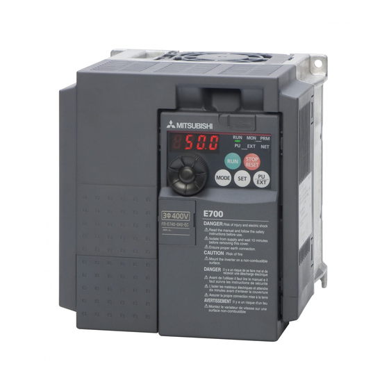
-
Contents
-
Table of Contents
-
Troubleshooting
-
Bookmarks
Quick Links
MITSUBISHI ELECTRIC
FR-E700
Frequency Inverter
Instruction Manual
FR-E740 EC
Art. no. 213994
INDUSTRIAL AUTOMATION
MITSUBISHI ELECTRIC
IB(NA)-0600336ENG
01102008
Version C
Related Manuals for Mitsubishi Electric FR-E700
Summary of Contents for Mitsubishi Electric FR-E700
-
Page 1: Instruction Manual
MITSUBISHI ELECTRIC FR-E700 Frequency Inverter Instruction Manual FR-E740 EC Art. no. 213994 INDUSTRIAL AUTOMATION MITSUBISHI ELECTRIC IB(NA)-0600336ENG 01102008 Version C…
-
Page 2
INVERTER FR-E700 INSTRUCTION MANUAL FR-E740-016 to 300 — EC FR-E720S-008 to 110 — EC OUTLINE WIRING PRECAUTIONS FOR USE OF THE INVERTER PARAMETERS TROUBLESHOOTING PRECAUTIONS FOR MAINTENANCE AND INSPECTION SPECIFICATIONS… -
Page 3
Thank you for choosing this Mitsubishi Inverter. This Instruction Manual provides instructions for advanced use of the FR-E700 series inverters. Incorrect handling might cause an unexpected fault. Before using the inverter, always read this instruction manual and the Installation Guideline [IB-0600335ENG] packed with the product carefully to use the equipment to its optimum performance. -
Page 4
3.Injury Prevention (3) Trial run CAUTION CAUTION Apply only the voltage specified in the instruction manual Before starting operation, confirm and adjust the to each terminal. Otherwise, burst, damage, etc. may parameters. A failure to do so may cause some machines occur. -
Page 5
(5) Emergency stop CAUTION Provide a safety backup such as an emergency brake which will prevent the machine and equipment from hazardous conditions if the inverter fails. When the breaker on the inverter input side trips, check for the wiring fault (short circuit), damage to internal parts of the inverter, etc. -
Page 6: Table Of Contents
CONTENTS OUTLINE Product checking and parts identification……… 2 Inverter and peripheral devices…………3 1.2.1 Peripheral devices …………………….. 4 Removal and reinstallation of the cover ……….5 1.3.1 Front cover……………………….5 1.3.2 Wiring cover………………………. 7 Installation of the inverter and enclosure design ……8 1.4.1 Inverter installation environment…………………
-
Page 7
3.1.1 Leakage currents and countermeasures ………………36 3.1.2 EMC measures ……………………..38 3.1.3 Power supply harmonics ………………….40 Installation of power factor improving reactor ……. 41 Power-OFF and magnetic contactor (MC)……..42 Inverter-driven 400V class motor ………… 43 Precautions for use of the inverter ……….44 Failsafe of the system which uses the inverter …… -
Page 8
4.7.3 Remote setting function (Pr. 59) ………………..98 Setting of acceleration/deceleration time and acceleration/ deceleration pattern …………..101 4.8.1 Setting of the acceleration and deceleration time (Pr. 7, Pr. 8, Pr. 20, Pr. 21, Pr. 44, Pr. 45, Pr. 147) …………..101 4.8.2 Starting frequency and start-time hold function (Pr. -
Page 9
4.14 Operation setting at fault occurrence ………. 161 4.14.1 Retry function (Pr. 65, Pr. 67 to Pr. 69) ………………161 4.14.2 Input/output phase loss protection selection (Pr. 251, Pr. 872) ……….163 4.14.3 Earth (ground) fault detection at start (Pr. 249) …………….. 163 4.15 Energy saving operation………….. -
Page 10
4.22 Useful functions …………….248 4.22.1 Cooling fan operation selection (Pr. 244) ……………… 248 4.22.2 Display of the life of the inverter parts (Pr. 255 to Pr. 259)…………249 4.22.3 Maintenance timer alarm (Pr. 503, Pr. 504)…………….253 4.22.4 Current average value monitor signal (Pr. 555 to Pr. 557) …………254 4.22.5 Free parameter (Pr. -
Page 11
PRECAUTIONS FOR MAINTENANCE AND INSPECTION Inspection items …………….288 6.1.1 Daily inspection …………………….. 288 6.1.2 Periodic inspection ……………………288 6.1.3 Daily and periodic inspection …………………. 289 6.1.4 Display of the life of the inverter parts ………………290 6.1.5 Checking the inverter and converter modules …………….291 6.1.6 Cleaning ……………………….. -
Page 12
MEMO… -
Page 13: Outline
Installation of the inverter and enclosure design …… 8 <Abbreviations> PU ……….Operation panel and parameter unit (FR-PU04 /FR-PU07 Inverter ……….. Mitsubishi inverter FR-E700 series E700 ……..Mitsubishi inverter FR-E700 series Pr………… Parameter number PU operation ……..Operation using the PU (operation panel/FR-PU04/FR-PU07) External operation ……
-
Page 14: Product Checking And Parts Identification
Product checking and parts identification Product checking and parts identification Unpack the inverter and check the capacity plate on the front cover and the rating plate on the inverter side face to ensure that the product agrees with your order and the inverter is intact. Inverter type FR — — EC…
-
Page 15: Inverter And Peripheral Devices
(Refer to page 27) Moulded case circuit breaker (MCCB) or earth leakage circuit breaker (ELB), fuse Inverter (FR-E700) The breaker must be selected carefully The life of the inverter is influenced by since an in-rush current flows in the surrounding temperature.
-
Page 16: Peripheral Devices
Inverter and peripheral devices 1.2.1 Peripheral devices Check the inverter type of the inverter you purchased. Appropriate peripheral devices must be selected according to the capacity. Refer to the following list and prepare appropriate peripheral devices: Moulded Case Circuit Breaker Magnetic Contactor (MC) (MCCB) ∗1 Motor…
-
Page 17: Removal And Reinstallation Of The Cover
Removal and reinstallation of the cover Removal and reinstallation of the cover 1.3.1 Front cover FR-E740-170 or less, FR-E720S Removal (Example of FR-E740-095) Remove the front cover by pulling it toward you in the direction of arrow. Reinstallation (Example of FR-E740-095) To reinstall, match the cover to the inverter front and install it straight.
-
Page 18
Removal and reinstallation of the cover FR-E740-230, 300 Removal (Example of FR-E740-230) 1) Loosen the installation screws of the front cover 1. 2) Remove the front cover 1 by pulling it toward you in the direction of arrow. 3) Remove the front cover 2 by pulling it toward you in the direction of arrow. Front cover 2 Front cover 1 Installation… -
Page 19: Wiring Cover
Removal and reinstallation of the cover 1.3.2 Wiring cover Removal and reinstallation The cover can be removed easily by pulling it toward you. To reinstall, fit the cover to the inverter along the guides. FR-E720S-008 to 030 FR-E740-016 to 095 FR-E720S-050 to 110 Guide Guide…
-
Page 20: Installation Of The Inverter And Enclosure Design
Installation of the inverter and enclosure design Installation of the inverter and enclosure design When an inverter panel is to be designed and manufactured, heat generated by contained equipment, etc., the environment of an operating place, and others must be fully considered to determine the panel structure, size and equipment layout. The inverter unit uses many semiconductor devices.
-
Page 21
Installation of the inverter and enclosure design Dust, dirt, oil mist Dust and dirt will cause such faults as poor contact of contact points, reduced insulation or reduced cooling effect due to moisture absorption of accumulated dust and dirt, and in-panel temperature rise due to clogged filter. In the atmosphere where conductive powder floats, dust and dirt will cause such faults as malfunction, deteriorated insulation and short circuit in a short time. -
Page 22: Cooling System Types For Inverter Panel
Installation of the inverter and enclosure design 1.4.2 Cooling system types for inverter panel From the panel that contains the inverter, the heat of the inverter and other equipment (transformers, lamps, resistors, etc.) and the incoming heat such as direct sunlight must be dissipated to keep the in-panel temperature lower than the permissible temperatures of the in-panel equipment including the inverter.
-
Page 23: Inverter Placement
Installation of the inverter and enclosure design 1.4.3 Inverter placement Installation of the inverter Enclosure surface mounting Remove the front cover and wiring cover to fix the inverter to the surface. FR-E720S-008 to 030 FR-E740-016 or more FR-E720S-050 or more Front cover Front cover Wiring cover…
-
Page 24
Installation of the inverter and enclosure design Above inverter Heat is blown up from inside the inverter by the small fan built in the unit. Any equipment placed above the inverter should be heat resistant. Arrangement of multiple inverters When multiple inverters are placed in the same enclosure, generally arrange them horizontally as shown in the right figure (a). -
Page 25: Wiring
WIRING This chapter describes the basic «WIRING» for use of this product. Always read the instructions before using the equipment Wiring………………… 14 Main circuit terminal specifications ……….15 Control circuit specifications …………20 Connection of stand-alone option unit ……..29…
-
Page 26: Terminal Connection Diagram
Wiring Wiring 2.1.1 Terminal connection diagram Source logic 1. DC reactor (FR-HEL) Main circuit terminal When connecting a DC reactor, remove the Control circuit terminal jumper across P1 and +. Single-phase power input Brake unit *6 A brake transistor is not built-in to the (Option) MCCB FR-E720S-008 and 015.
-
Page 27: Main Circuit Terminal Specifications
Main circuit terminal specifications Main circuit terminal specifications 2.2.1 Specification of main circuit terminal Terminal Terminal Name Description Symbol R/L1, Connect to the commercial power supply. S/L2, AC power input Keep these terminals open when using the high power factor converter (FR-HC) or T/L3 ∗1 power regeneration common converter (FR-CV).
-
Page 28: Terminal Arrangement Of The Main Circuit Terminal, Power Supply And The Motor Wiring
Main circuit terminal specifications 2.2.2 Terminal arrangement of the main circuit terminal, power supply and the motor wiring Three-phase 400V class FR-E740-016 to 095 FR-E740-120, 170 Jumper Screw size (M4) Jumper R/L1 S/L2 T/L3 Screw size (M4) R/L1 S/L2 T/L3 + PR Screw size (M4)
-
Page 29: Cables And Wiring Length
Main circuit terminal specifications 2.2.3 Cables and wiring length Applied wire size Select the recommended cable size to ensure that a voltage drop will be 2% max. If the wiring distance is long between the inverter and motor, a main circuit cable voltage drop will cause the motor torque to decrease especially at the output of a low frequency.
-
Page 30
Main circuit terminal specifications Earthing (Grounding) precautions Always earth (ground) the motor and inverter. 1) Purpose of earthing (grounding) Generally, an electrical apparatus has an earth (ground) terminal, which must be connected to the ground before use. An electrical circuit is usually insulated by an insulating material and encased. However, it is impossible to manufacture an insulating material that can shut off a leakage current completely, and actually, a slight current flow into the case. -
Page 31
Main circuit terminal specifications Total wiring length The overall wiring length for connection of a single motor or multiple motors should be within the value in the table below. 200V class Pr. 72 PWM frequency selection Setting (carrier frequency) 1 (1kHz) or less 200m 200m 300m… -
Page 32: Control Circuit Specifications
Control circuit specifications Control circuit specifications 2.3.1 Standard control circuit terminal indicates that terminal functions can be selected using Pr. 178 to Pr. 184, Pr. 190 to Pr. 192 (I/O terminal function selection). (Refer to page 130). Input signal Terminal Refer to Type Terminal Name…
-
Page 33
Control circuit specifications Terminal Refer to Type Terminal Name Description Rated Specifications Symbol Page 5.2V ± 0.2VDC Used as power supply when connecting potentiometer Frequency setting power for frequency setting (speed setting) from outside of permissible load current supply the inverter. (Refer to Pr. 73 Analog input selection.) 10mA Inputting 0 to 5VDC (or 0 to 10V) provides the Input resistance10kΩ… -
Page 34
Control circuit specifications Output signal Terminal Reference Type Terminal Name Description Rated Specifications Symbol Page 1 changeover contact output indicates that the inverter Contact capacity:230VAC Relay output (fault protective function has activated and the output stopped. 0.3A A, B, C output) Fault: discontinuity across B-C (continuity across A-C), (power factor =0.4) -
Page 35: Changing The Control Logic
Control circuit specifications 2.3.2 Changing the control logic The input signals are set to source logic (SOURCE) when shipped from the factory. To change the control logic, the jumper connector above the control terminal must be moved to the other position. To change to sink logic, change the jumper connector in the source logic (SOURCE) position to sink logic (SINK) position using tweezers, a pair of long-nose pliers etc.
-
Page 36
Control circuit specifications (1) Sink logic type and source logic type In sink logic, a signal switches ON when a current flows from the corresponding signal input terminal. Terminal SD is common to the contact input signals. Terminal SE is common to the open collector output signals. In source logic, a signal switches ON when a current flows into the corresponding signal input terminal. -
Page 37: Wiring Of Control Circuit
Control circuit specifications 2.3.3 Wiring of control circuit Standard control circuit terminal layout Terminal screw size M3: (Terminal A, B, C) M2: (Other than the above) 4 RUN FU SE STF STR Wiring method 1) Strip off the sheath of the wire of the control circuit to wire. Strip off the sheath about the size below.
-
Page 38: Wiring Instructions
Control circuit specifications Signal inputs by contactless switches The contacted input terminals of the inverter (STF, STR, RH, RM, RL, MRS, RES) can be controlled using a Inverter transistor instead of a contacted switch as shown on the right. +24V STF, etc.
-
Page 39: Connection To The Pu Connector
Control circuit specifications 2.3.5 Connection to the PU connector Using the PU connector, you can perform communication operation from the parameter unit (FR-PU07), enclosure surface operation panel (FR-PA07) or a personal computer etc. Refer to the figure below to open the PU connector cover. PU connector To open the cover Place a flathead screwdriver, etc.
-
Page 40
Pins No. 2 and 8 provide power to the parameter unit. Do not use these pins for RS-485 communication. When making RS-485 communication between the FR-E700 series, FR-E500 series and FR-S500 series, incorrect connection of pins No.2 and 8 (parameter unit power supply) of the above PU connector may result in the inverter malfunction or failure. -
Page 41: Connection Of Stand-Alone Option Unit
Connection of stand-alone option unit Connection of stand-alone option unit The inverter accepts a variety of stand-alone option units as required. Incorrect connection will cause inverter damage or accident. Connect and operate the option unit carefully in accordance with the corresponding option unit manual. 2.4.1 Connection of a dedicated external brake resistor (MRS type, FR-ABR) (FR-E740- 016 or more, FR-E720S-030 or more)
-
Page 42
Connection of stand-alone option unit When using the brake resistor (MRS type) and high-duty brake resistor (FR-ABR) It is recommended to configure a sequence, which shuts off power in the input side of the inverter by the external thermal relay as shown below, to prevent overheat and burnout of the brake resistor (MRS type) and high duty brake resistor (FR- ABR) in case the regenerative brake transistor is damaged. -
Page 43: Connection Of The Brake Unit (Fr-Bu2)
Connection of stand-alone option unit 2.4.2 Connection of the brake unit (FR-BU2) Connect the brake unit (FR-BU2(-H)) as shown below to improve the braking capability at deceleration. If the transistors in the brake unit should become faulty, the resistor can be unusually hot. To prevent unusual overheat and fire, install a magnetic contactor on the inverter’s input side to configure a circuit so that a current is shut off in case of fault.
-
Page 44: Connection Of The High Power Factor Converter (Fr-Hc)
Connection of stand-alone option unit Connection example with the FR-BR(-H) type resistor ∗2 FR-BR MCCB Motor ∗4 R/L1 Three-phase AC S/L2 power supply T/L3 ∗3 FR-BU2 Inverter ∗1 ∗1 ∗5 ∗3 5m or less ∗1 Connect the inverter terminals (+ and -) and brake unit (FR-BU2) terminals so that their terminal names match with each other.
-
Page 45: Connection Of The Power Regeneration Common Converter (Fr-Cv)
Connection of stand-alone option unit 2.4.4 Connection of the power regeneration common converter (FR-CV) When connecting the power regeneration common converter (FR-CV), connect the inverter terminals (+, -) and power regeneration common converter (FR-CV) terminals as shown below so that their symbols match with each other. R/L1 S/L2 T/L3…
-
Page 46
MEMO… -
Page 47: Precautions For Use Of The Inverter
PRECAUTIONS FOR USE OF THE INVERTER This chapter explains the «PRECAUTIONS FOR USE OF THE INVERTER» for use of this product. Always read the instructions before using the equipment EMC and leakage currents …………36 Installation of power factor improving reactor ……41 Power-OFF and magnetic contactor (MC) ………
-
Page 48: Emc And Leakage Currents
EMC and leakage currents EMC and leakage currents 3.1.1 Leakage currents and countermeasures Capacitances exist between the inverter I/O cables, other cables and earth and in the motor, through which a leakage current flows. Since its value depends on the static capacitances, carrier frequency, etc., low acoustic noise operation at the increased carrier frequency of the inverter will increase the leakage current.
-
Page 49
EMC and leakage currents Selection of rated sensitivity current of earth (ground) leakage current breaker When using the earth leakage current breaker with the inverter circuit, select its rated sensitivity current as follows, independently of the PWM carrier frequency. Breaker designed for harmonic and Ig1, Ig2: Leakage currents in wire path during commercial surge suppression power supply operation… -
Page 50: Emc Measures
EMC and leakage currents 3.1.2 EMC measures Some electromagnetic noises enter the inverter to malfunction it and others are radiated by the inverter to malfunction peripheral devices. Though the inverter is designed to have high immunity performance, it handles low-level signals, so it requires the following basic techniques.
-
Page 51
EMC and leakage currents Propagation Path Measures When devices that handle low-level signals and are liable to malfunction due to electromagnetic noises, e.g. instruments, receivers and sensors, are contained in the enclosure that contains the inverter or when their signal cables are run near the inverter, the devices may be malfunctioned by air-propagated electromagnetic noises. -
Page 52: Power Supply Harmonics
EMC and leakage currents 3.1.3 Power supply harmonics The inverter may generate power supply harmonics from its converter circuit to affect the power generator, power capacitor etc. Power supply harmonics are different from noise and leakage currents in source, frequency band and transmission path. Take the following countermeasure suppression techniques.
-
Page 53: Installation Of Power Factor Improving Reactor
Installation of power factor improving reactor Installation of power factor improving reactor When the inverter is connected near a large-capacity power transformer (500kVA or more) or when a power capacitor is to be switched over, an excessive peak current may flow in the power input circuit, damaging the converter circuit. To prevent this, always install an optional reactor (FR-HAL, FR-HEL).
-
Page 54: Power-Off And Magnetic Contactor (Mc)
Power-OFF and magnetic contactor (MC) Power-OFF and magnetic contactor (MC) Inverter input side magnetic contactor (MC) On the inverter input side, it is recommended to provide an MC for the following purposes. (Refer to page 4 for selection.) 1) To release the inverter from the power supply when the fault occurs or when the drive is not functioning (e.g. emergency stop operation).
-
Page 55: Inverter-Driven 400V Class Motor
Inverter-driven 400V class motor Inverter-driven 400V class motor In the PWM type inverter, a surge voltage attributable to wiring constants is generated at the motor terminals. Especially for a 400V class motor, the surge voltage may deteriorate the insulation. When the 400V class motor is driven by the inverter, consider the following measures: Measures It is recommended to take either of the following measures:…
-
Page 56: Precautions For Use Of The Inverter
Precautions for use of the inverter Precautions for use of the inverter The FR-E700 series is a highly reliable product, but incorrect peripheral circuit making or operation/handling method may shorten the product life or damage the product. Before starting operation, always recheck the following items.
-
Page 57
Precautions for use of the inverter (12) Do not apply a voltage higher than the permissible voltage to the inverter I/O signal circuits. Application of a voltage higher than the permissible voltage to the inverter I/O signal circuits or opposite polarity may damage the I/O devices. -
Page 58: Failsafe Of The System Which Uses The Inverter
Failsafe of the system which uses the inverter Failsafe of the system which uses the inverter When a fault occurs, the inverter trips to output a fault signal. However, a fault output signal may not be output at an inverter fault occurrence when the detection circuit or output circuit fails, etc.
-
Page 59
Failsafe of the system which uses the inverter 4) Checking the motor operating status by the start signal input to the inverter and inverter output current detection signal. The output current detection signal (Y12 signal) is output when the inverter operates and currents flows in the motor. Check if Y12 signal is output when inputting the start signal to the inverter (forward signal is STF signal and reverse signal is STR signal). -
Page 60
MEMO… -
Page 61: Parameters
PARAMETERS This chapter explains the «PARAMETERS» for use of this product. Always read the instructions before using the equipment The abbreviations in the explanations below are as follows: ..V/F control, ..Advanced magnetic flux vector control, AD MFVC AD MFVC AD MFVC ..General-purpose magnetic-flux vector control GP MFVC GP MFVC…
-
Page 62: Operation Panel
Operation panel Operation panel 4.1.1 Names and functions of the operation panel The operation panel cannot be removed from the inverter. Operating status display Operation mode indication Lit or flicker during inverter operation. ∗ PU: Lit to indicate PU operation mode. EXT: Lit to indicate External operation mode.
-
Page 63: Basic Operation (Factory Setting)
Operation panel 4.1.2 Basic operation (factory setting) Operation mode switchover At powering on (external operation mode) PU Jog operation mode (Example) PU operation mode Value change and frequency flicker. (output frequency monitor) Frequency setting has been written and completed!! STOP Output current monitor Output voltage monitor Display the…
-
Page 64: Easy Operation Mode Setting (Easy Setting Mode)
Operation panel 4.1.3 Easy operation mode setting (easy setting mode) Setting of Pr. 79 Operation mode selection according to combination of the start command and speed command can be easily made. Operation Start command: external (STF/STR), frequency command: operate with example Operation Display…
-
Page 65: Change The Parameter Setting Value
Operation panel 4.1.4 Change the parameter setting value Changing Change the Pr. 1 Maximum frequency setting. example Operation Display Screen at powering ON The monitor display appears. PU indication is lit. Press to choose the PU operation mode. PRM indication is lit. Press to choose the parameter setting mode.
-
Page 66: Parameter List
Parameter list Parameter list Parameter list 4.2.1 Parameter list For simple variable-speed operation of the inverter, the initial setting of the parameters may be used as they are. Set the necessary parameters to meet the load and operational specifications. Parameter setting, change and check can be made Symbols in the table indicate parameters which function when an option is mounted.
-
Page 67
Parameter list Parameter list Control Mode-based Minimum Refer Instruction Code Parameter Func- Initial Customer Correspondence Table Parameter Name Setting Range Setting Parameter Remarks tion Value Setting Increments Page Read Write Extended Copy Clear All clear AD MFVC AD MFVC AD MFVC GP MFVC GP MFVC GP MFVC… -
Page 68
Parameter list Parameter list Control Mode-based Minimum Refer Instruction Code Parameter Func- Initial Customer Correspondence Table Parameter Name Setting Range Setting Parameter Remarks tion Value Setting Increments Page Read Write Extended Copy Clear All clear AD MFVC AD MFVC AD MFVC GP MFVC GP MFVC GP MFVC… -
Page 69
Parameter list Parameter list Control Mode-based Minimum Refer Instruction Code Parameter Func- Initial Customer Correspondence Table Parameter Name Setting Range Setting Parameter Remarks tion Value Setting Increments Page Read Write Extended Copy Clear All clear AD MFVC AD MFVC AD MFVC GP MFVC GP MFVC GP MFVC… -
Page 70
Parameter list Parameter list Control Mode-based Minimum Refer Instruction Code Parameter Func- Initial Customer Correspondence Table Parameter Name Setting Range Setting Parameter Remarks tion Value Setting Increments Page Read Write Extended Copy Clear All clear AD MFVC AD MFVC AD MFVC GP MFVC GP MFVC GP MFVC… -
Page 71
Parameter list Parameter list Control Mode-based Minimum Refer Instruction Code Parameter Func- Initial Customer Correspondence Table Parameter Name Setting Range Setting Parameter Remarks tion Value Setting Increments Page Read Write Extended Copy Clear All clear AD MFVC AD MFVC AD MFVC GP MFVC GP MFVC GP MFVC… -
Page 72
Parameter list Parameter list Control Mode-based Minimum Refer Instruction Code Parameter Func- Initial Customer Correspondence Table Parameter Name Setting Range Setting Parameter Remarks tion Value Setting Increments Page Read Write Extended Copy Clear All clear AD MFVC AD MFVC AD MFVC GP MFVC GP MFVC GP MFVC… -
Page 73
Parameter list Parameter list Control Mode-based Minimum Refer Instruction Code Parameter Func- Initial Customer Correspondence Table Parameter Name Setting Range Setting Parameter Remarks tion Value Setting Increments Page Read Write Extended Copy Clear All clear AD MFVC AD MFVC AD MFVC GP MFVC GP MFVC GP MFVC… -
Page 74
Parameter list Parameter list Control Mode-based Minimum Refer Instruction Code Parameter Func- Initial Customer Correspondence Table Parameter Name Setting Range Setting Parameter Remarks tion Value Setting Increments Page Read Write Extended Copy Clear All clear AD MFVC AD MFVC AD MFVC GP MFVC GP MFVC GP MFVC… -
Page 75: Control Mode
Parameters according to purposes Control mode 4.3.1 Change the control method (Pr. 80, Pr. 81, Pr. 800) …………..76 Adjust the output torque (current) of the motor 4.4.1 Manual torque boost (Pr. 0, Pr. 46) ………………..77 4.4.2 Advanced magnetic flux vector control (Pr. 71, Pr. 80, Pr. 81, Pr.89, Pr. 800) ……78 4.4.3 General-purpose magnetic flux vector control (Pr.
-
Page 76
4.11.3 Condition selection of function validity by second function selection signal (RT) ……. 133 4.11.4 Start signal operation selection (STF, STR, STOP signal, Pr. 250) ……….. 134 4.11.5 Output terminal function selection (Pr. 190 to Pr. 192)…………… 136 4.11.6 Detection of output frequency (SU, FU signal, Pr. 41 to Pr. 43) ……….140 4.11.7 Output current detection function (Y12 signal, Y13 signal, Pr. -
Page 77
4.20 Communication operation and setting 4.20.1 Wiring and configuration of PU connector ……………… 199 4.20.2 Initial settings and specifications of RS-485 communication (Pr. 117 to Pr. 120, Pr. 123, Pr. 124, Pr. 549) …………….202 4.20.3 Operation selection at communication error occurrence (Pr. 121, Pr. 122, Pr. 502) ….203 4.20.4 Communication EEPROM write selection (Pr. -
Page 78
Control mode Control mode V/F control (initial setting), Advanced magnetic flux vector control and General-purpose magnetic flux vector control are available with this inverter. V/F Control It controls frequency and voltage so that the ratio of frequency (F) to voltage (V) is constant when changing frequency. Advanced (General-purpose) magnetic flux vector control This control divides the inverter output current into an excitation current and a torque current by vector calculation and makes voltage compensation to flow a motor current which meets the load torque. -
Page 79: Change The Control Method (Pr. 80, Pr. 81, Pr. 800)
Control mode 4.3.1 Change the control method (Pr. 80, Pr. 81, Pr. 800) Set when selecting the control method for Advanced magnetic flux vector control and General-purpose magnetic flux vector control. The initial value is V/F control. Select a control mode using Pr. 800 Control method selection. Parameter Initial Name…
-
Page 80: Adjust The Output Torque (Current) Of The Motor
Adjust the output torque (current) of the motor Adjust the output torque (current) of the motor Purpose Parameter that should be Set Refer to Page Set starting torque manually Manual torque boost Pr. 0, Pr. 46 Advanced magnetic flux Automatically control output current vector control, Pr.
-
Page 81: Advanced Magnetic Flux Vector Control (Pr. 71, Pr. 80, Pr. 81, Pr.89, Pr. 800)
Adjust the output torque (current) of the motor 4.4.2 Advanced magnetic flux vector control (Pr. 71, Pr. 80, Pr. 81, Pr.89, Pr. 800) AD MFVC AD MFVC AD MFVC Advanced magnetic flux vector control can be selected by setting the capacity, poles and type of the motor used in Pr. 80 and Pr.
-
Page 82
Adjust the output torque (current) of the motor <Selection method of Advanced magnetic flux vector control> Perform secure wiring. (Refer to page 14) Set the motor. (Pr. 71) Pr. 71 Setting ∗1 Motor Remarks Mitsubishi standard SF-JR 0 (initial value) motor SF-HR Mitsubishi high… -
Page 83
The motor speed fluctuation at load fluctuation can be adjusted using Pr. 89. (It is useful when the speed command does not match the motor speed after the FR-E500 series inverter is replaced with the FR-E700 series inverter, etc.) Speed Parameters referred to Pr. -
Page 84: General-Purpose Magnetic Flux Vector Control (Pr. 71, Pr. 80, Pr. 81, Pr. 800)
Adjust the output torque (current) of the motor 4.4.3 General-purpose magnetic flux vector control (Pr. 71, Pr. 80, Pr. 81, Pr. 800) GP MFVC GP MFVC GP MFVC General-purpose magnetic flux vector control is the same function as the FR-E500 series. Select this control when the same operation characteristic is necessary.
-
Page 85
Adjust the output torque (current) of the motor <Selection method of General-purpose magnetic flux vector control> Perform secure wiring. (Refer to page 14) Set the motor.(Pr. 71) Pr. 71 Setting ∗1 Motor Remarks Mitsubishi standard SF-JR 0 (initial value) motor SF-HR Mitsubishi high ∗2… -
Page 86: Slip Compensation (Pr. 245 To Pr. 247)
Adjust the output torque (current) of the motor 4.4.4 Slip compensation (Pr. 245 to Pr. 247) GP MFVC GP MFVC GP MFVC When V/F control or General-purpose magnetic flux vector control is performed, the inverter output current may be used to assume motor slip to keep the motor speed constant. Parameter Name Initial Value…
-
Page 87: Stall Prevention Operation (Pr. 22, Pr. 23, Pr. 48, Pr. 66, Pr. 156, Pr. 157, Pr. 277)
Adjust the output torque (current) of the motor 4.4.5 Stall prevention operation (Pr. 22, Pr. 23, Pr. 48, Pr. 66, Pr. 156, Pr. 157, Pr. 277) This function monitors the output current and automatically changes the output frequency to prevent the inverter from coming to trip due to overcurrent, overvoltage, etc.
-
Page 88
Adjust the output torque (current) of the motor Setting of stall prevention operation level (Pr. 22) Pr. 22 Set in the percentage of the output current to the rated inverter current at which stall prevention operation will be Output current performed. -
Page 89
Adjust the output torque (current) of the motor Setting of stall prevention operation in high frequency range (Pr. 22, Pr. 23, Pr. 66) Setting example Pr. 22 = 150% Pr. 23 = 100% Pr. 22 When Pr. 23 = 9999 Pr. -
Page 90
Adjust the output torque (current) of the motor Limit the stall prevention operation and fast-response current limit operation according to the operating status (Pr. 156) Refer to the following table and select whether stall prevention operation and fast-response current limit operation will be performed or not and the operation to be performed at OL signal output. -
Page 91: Limit The Output Frequency
Limit the output frequency Limit the output frequency Purpose Parameter that should be Set Refer to Page Set upper limit and lower limit of Maximum/minimum Pr. 1, Pr. 2, Pr. 18 output frequency frequency Perform operation by avoiding Frequency jump Pr.
-
Page 92: Avoid Mechanical Resonance Points (Frequency Jumps) (Pr. 31 To Pr. 36)
Limit the output frequency 4.5.2 Avoid mechanical resonance points (frequency jumps) (Pr. 31 to Pr. 36) When it is desired to avoid resonance attributable to the natural frequency of a mechanical system, these parameters allow resonant frequencies to be jumped. Parameter Name Initial Value…
-
Page 93: Set V/F Pattern
Set V/F pattern Set V/F pattern Purpose Parameter that should be Set Refer to Page Base frequency, Set motor ratings Pr. 3, Pr. 19, Pr. 47 Base frequency voltage Select a V/F pattern according to Load pattern selection Pr. 14 applications.
-
Page 94
Set V/F pattern Base frequency voltage setting (Pr. 19) Use Pr. 19 Base frequency voltage to set the base voltage (e.g. rated motor voltage). If the setting is less than the power supply voltage, the maximum output voltage of the inverter is as set in Pr. 19. Pr. -
Page 95: Load Pattern Selection (Pr. 14)
Set V/F pattern 4.6.2 Load pattern selection (Pr. 14) You can select the optimum output characteristic (V/F characteristic) for the application and load characteristics. Parameter Name Initial Value Setting Range Description Number For constant-torque load For variable torque load For constant-torque elevators Load pattern selection (at reverse rotation boost of 0%) For constant-torque elevators…
-
Page 96
Set V/F pattern (3) Constant-torque load application Pr. 14 = 3 Pr. 14 = 2 (setting «2, 3») For vertical lift loads For vertical lift loads Set «2» when a vertical lift load is fixed as power At forward rotation boost…0% At forward rotation boost…Pr. -
Page 97: Frequency Setting By External Terminals
Frequency setting by external terminals Frequency setting by external terminals Purpose Parameter that should be Set Refer to Page Make frequency setting by Pr. 4 to Pr. 6, Pr. 24 to Pr. 27, Multi-speed operation combination of terminals Pr. 232 to Pr. 239 Perform jog operation Jog operation Pr.
-
Page 98
Frequency setting by external terminals Multi-speed setting for 4 or more speeds (Pr. 24 to Pr. 27, Pr. 232 to Pr. 239) Frequency from 4 speed to 15 speed can be set according to the combination of the RH, RM, RL and REX signals. Set the running frequencies in Pr. -
Page 99: Jog Operation (Pr. 15, Pr. 16)
Frequency setting by external terminals 4.7.2 Jog operation (Pr. 15, Pr. 16) You can set the frequency and acceleration/deceleration time for Jog operation. Jog operation can be performed in either of the External and the PU operation mode. This operation can be used for conveyor positioning, test operation, etc. Parameter Initial Name…
-
Page 100
Frequency setting by external terminals Jog operation from PU Selects Jog operation mode from the operation panel and PU (FR-PU04/FR-PU07). Operation is performed only while the start button is pressed. Inverter R/L1 Three-phase AC S/L2 Motor power supply T/L3 Operation panel Operation Display Confirmation of the RUN indication and… -
Page 101: Remote Setting Function (Pr. 59)
Frequency setting by external terminals NOTE When Pr. 29 Acceleration/deceleration pattern selection = «1» (S-pattern acceleration/deceleration A), the acceleration/ deceleration time is the period of time required to reach Pr. 3 Base frequency. The Pr. 15 setting should be equal to or higher than the Pr. 13 Starting frequency. Starting frequency The JOG signal can be assigned to the input terminal using any of Pr.
-
Page 102
Frequency setting by external terminals Remote setting function Use Pr. 59 to select whether the remote setting function is used or not and whether the frequency setting storage function in the remote setting mode is used or not. When Pr. 59 is set to any of «1 to 3» (remote setting function valid), the functions of the RH, RM and RL signals are changed to acceleration (RH), deceleration (RM) and clear (RL). -
Page 103
Frequency setting by external terminals REMARKS During jog operation or PID control operation, the remote setting function is invalid. Setting frequency is «0» Even when remotely-set frequency is cleared by turning ON the RL (clear) signal after turn Remotely-set frequency stored last time OFF (ON) of both the RH and RM Within 1 minute signals, the inverter operates at… -
Page 104: Setting Of Acceleration/Deceleration Time And Acceleration/ Deceleration Pattern
Setting of acceleration/deceleration time and acceleration/ deceleration pattern Setting of acceleration/deceleration time and acceleration/ deceleration pattern Purpose Parameter that should be Set Refer to Page Motor acceleration/deceleration Acceleration/deceleration Pr. 7, Pr. 8, Pr. 20, Pr. 21, Pr. 44, time setting times Pr.
-
Page 105
Setting of acceleration/deceleration time and acceleration/ deceleration pattern Acceleration time setting (Pr. 7, Pr. 20) Use Pr. 7 Acceleration time to set the acceleration time required to reach Pr. 20 Pr. 20 Running Acceleration/deceleration reference frequency from 0Hz. (50Hz) frequency Set the acceleration time according to the following formula. -
Page 106
Setting of acceleration/deceleration time and acceleration/ deceleration pattern Set two kinds of acceleration/deceleration times (RT signal, Pr. 44, Pr. 45, Pr. 147 ) Pr. 44 and Pr. 45 are valid when the RT signal is ON, or the output frequency reaches or exceeds the setting of Pr. 147. When «9999»… -
Page 107: Starting Frequency And Start-Time Hold Function (Pr. 13, Pr. 571)
Setting of acceleration/deceleration time and acceleration/ deceleration pattern 4.8.2 Starting frequency and start-time hold function (Pr. 13, Pr. 571) You can set the starting frequency and hold the set starting frequency for a certain period of time. Set these functions when you need the starting torque or want to smooth motor drive at a start. Parameter Name Initial Value…
-
Page 108: Acceleration/Deceleration Pattern (Pr. 29)
Setting of acceleration/deceleration time and acceleration/ deceleration pattern 4.8.3 Acceleration/deceleration pattern (Pr. 29) You can set the acceleration/deceleration pattern suitable for application. Parameter Name Initial Value Setting Range Description Number Linear acceleration/ deceleration Acceleration/deceleration S-pattern acceleration/deceleration A pattern selection S-pattern acceleration/deceleration B The above parameters can be set when Pr.
-
Page 109: Shortest Acceleration/Deceleration (Automatic Acceleration/Deceleration) (Pr. 61 To Pr. 63, Pr. 292, Pr. 293)
Setting of acceleration/deceleration time and acceleration/ deceleration pattern 4.8.4 Shortest acceleration/deceleration (automatic acceleration/deceleration) (Pr. 61 to Pr. 63, Pr. 292, Pr. 293) The inverter operates in the same conditions as when appropriate values are set in each parameter even if acceleration/deceleration time and V/F pattern are not set.
-
Page 110
Setting of acceleration/deceleration time and acceleration/ deceleration pattern Adjustment of shortest acceleration/deceleration mode (Pr. 61 to Pr. 63) By setting the adjustment parameters Pr. 61 and Pr. 63, the application range can be made wider. Parameter Name Setting Range Description Number For example, when the motor and inverter are different in capacity, set the rated motor current value. -
Page 111: Selection And Protection Of A Motor
Selection and protection of a motor Selection and protection of a motor Purpose Parameter that should be Set Refer to Page Motor protection from overheat Electronic thermal O/L relay Pr. 9, Pr. 51 Use the constant-torque motor Applied motor Pr. 71 The motor performance can be Pr.
-
Page 112
Selection and protection of a motor Set two different electronic thermal O/L relays (Pr. 51) Use this function when running two motors of different rated currents individually by a single inverter. (When running two motors together, use external thermal relays.) Set the rated current of the second motor to Pr. -
Page 113: Applied Motor (Pr. 71, Pr. 450)
Selection and protection of a motor 4.9.2 Applied motor (Pr. 71, Pr. 450) Setting of the used motor selects the thermal characteristic appropriate for the motor. Setting is required to use a constant-torque motor. Thermal characteristic of the electronic thermal relay function suitable for the motor is set.
-
Page 114
Selection and protection of a motor Use two motors (Pr. 450) Set Pr. 450 Second applied motor to use two different motors with one inverter. When «9999» (initial value) is set, no function is selected. When a value other than 9999 is set in Pr. 450, the second motor is valid when the RT signal turns ON. For the RT signal, set «3»… -
Page 115: To Exhibit The Best Performance Of The Motor Performance (Offline Auto Tuning) (Pr. 71, Pr. 80 To Pr. 84, Pr. 90 To Pr. 94, Pr. 96, Pr. 859)
Selection and protection of a motor 4.9.3 To exhibit the best performance of the motor performance (offline auto tuning) (Pr. 71, Pr. 80 to Pr. 84, Pr. 90 to Pr. 94, Pr. 96, Pr. 859) The motor performance can be maximized with offline auto tuning. What is offline auto tuning? When performing Advanced magnetic flux vector control or General-purpose magnetic flux vector control, the motor can be run with the optimum operating characteristics by automatically measuring the motor constants (offline auto…
-
Page 116
Selection and protection of a motor The setting range and increments of Pr. 82, Pr. 90 to Pr. 94 and Pr. 859 changes according to the setting value of Pr. 71 and Pr. 96. Auto Tuning Measured Value Internal Stored Value ∗1 Direct Input Value ∗2 Applied Motor ∗3… -
Page 117
Selection and protection of a motor Setting 1) Select Advanced magnetic flux vector control (Refer to page 78) or General-purpose magnetic flux vector control (Refer to page 81). 2) Set «1» or «11» in Pr. 96 Auto tuning setting/status. When the setting is «1» ..Tune all motor constants without running the motor. When performing Advanced magnetic flux vector control, set «1»… -
Page 118
Selection and protection of a motor Execution of tuning POINT Before performing tuning, check the monitor display of the operation panel or parameter unit (FR-PU04/FR-PU07) if the inverter is in the status for tuning. (Refer to 2) below) When the start command is turned ON under V/F control, the motor starts. -
Page 119
Selection and protection of a motor 3) When offline auto tuning ends, press of the operation panel during PU operation. For external operation, turn OFF the start signal (STF signal or STR signal) once. This operation resets the offline auto tuning and the PU’s monitor display returns to the normal indication. (Without this operation, next operation cannot be started.) REMARKS Do not change the Pr. -
Page 120
Selection and protection of a motor Utilizing or changing offline auto tuning data for use The data measured in the offline auto tuning can be read and utilized or changed. <Operating procedure> 1) Set Pr. 71 according to the motor used. Pr. -
Page 121
Selection and protection of a motor Method to set the motor constants without using the offline auto tuning data The Pr. 90 to Pr. 94 motor constants may either be entered in [Ω] or in [mH]. Before starting operation, confirm which motor constant unit is used. -
Page 122
Selection and protection of a motor To enter the Pr. 90 to Pr. 94 motor constants in [mH] <Operating procedure> 1) Set Pr. 71 according to the motor used. Pr.71 Setting ∗1 Motor Mitsubishi standard motor SF-JR SF-HR Mitsubishi high efficiency motor SF-JRCA 4P Mitsubishi constant-torque motor SF-HRCA… -
Page 123: Motor Brake And Stop Operation
Motor brake and stop operation 4.10 Motor brake and stop operation Purpose Parameter that should be Set Refer to Page Motor braking torque adjustment DC Injection brake Pr. 10 to Pr. 12 Improve the motor braking torque with Selection of a Pr.
-
Page 124: Selection Of A Regenerative Brake (Pr. 30, Pr. 70)
Motor brake and stop operation REMARKS For the FR-E740-120 and 170, when the Pr. 12 setting is the following, changing the Pr. 71 Applied motor setting automatically changes the Pr. 12 setting. Therefore, it is not necessary to change the Pr. 12 setting. (a) When 4% (initial value) is set in Pr.
-
Page 125
Motor brake and stop operation When using the high-duty brake resistor (FR-ABR) (FR-E740-016 or more, FR-E720S-030 or more) Set «1» in Pr. 30. Set Pr. 70 as follows. FR-E740-170 or less, FR-E720S-110 or less, ……………… 10% FR-E740-230 and 300 ……………………6% When a high power factor converter (FR-HC) is used and automatic restart after instantaneous power failure function is made valid. -
Page 126: Stop Selection (Pr. 250)
Motor brake and stop operation 4.10.3 Stop selection (Pr. 250) Used to select the stopping method (deceleration to a stop or coasting) when the start signal turns OFF. Used to stop the motor with a mechanical brake, etc. together with switching OFF of the start signal. You can also select the operations of the start signals (STF/STR).
-
Page 127: Stop-On Contact Control Function (Pr. 6, Pr. 48, Pr. 270, Pr. 275, Pr. 276)
Motor brake and stop operation 4.10.4 Stop-on contact control function (Pr. 6, Pr. 48, Pr. 270, Pr. 275, Pr. 276) AD MFVC AD MFVC AD MFVC GP MFVC GP MFVC GP MFVC To ensure accurate positioning at the upper limit etc. of a <Without stop-on-contact control>…
-
Page 128
Motor brake and stop operation Function switching of stop-on-contact control selection Normal Operation With stop-on-contact Control Main Functions (either RL or RT is OFF or both are OFF) (both RL and RT are ON) Multi-speed Output frequency 0 to 5V, 0 to 10V Pr. -
Page 129: Brake Sequence Function (Pr. 278 To Pr. 283, Pr. 292)
Motor brake and stop operation 4.10.5 Brake sequence function (Pr. 278 to Pr. 283, Pr. 292) AD MFVC AD MFVC AD MFVC GP MFVC GP MFVC GP MFVC This function is used to output from the inverter the mechanical brake operation timing signal in vertical lift and other applications.
-
Page 130
Motor brake and stop operation Set the brake sequence mode Select Advanced magnetic flux vector control or General-purpose magnetic flux vector control. The brake sequence function is valid only when the External operation mode, External/PU combined operation mode 1 or Network operation mode is selected. -
Page 131
Motor brake and stop operation Without brake opening completion signal input (Pr.292 = «8») When the start signal is input to the inverter, the inverter starts running. When the internal speed command reaches the value set in Pr. 278 and the output current is not less than the value set in Pr. 279 , the inverter outputs the brake opening request signal (BOF) after the time set in Pr. -
Page 132
Motor brake and stop operation Protective functions If any of the following errors occurs during the brake sequence operation, the inverter results in a fault, trips, and turns OFF the brake opening request signal (BOF). Fault Display Description Although more than 2s have elapsed after the start command (forward or reverse rotation) is input, the brake opening E.MB4 request signal (BOF) does not turn ON. -
Page 133: Function Assignment Of External Terminal And Control
Function assignment of external terminal and control 4.11 Function assignment of external terminal and control Purpose Parameter that should be Set Refer to Page Input terminal function Assign function to input terminal Pr. 178 to Pr. 184 selection Set MRS signal (output shutoff) to MRS input selection Pr.
-
Page 134
Function assignment of external terminal and control Refer to Setting Signal Function Related Parameters Page Second function selection Pr. 44 to Pr. 51 Pr. 270 = 1 ∗2 Stop-on contact selection 1 Pr. 270, Pr. 275, Pr. 276 Terminal 4 input selection Pr. -
Page 135: Inverter Output Shutoff Signal (Mrs Signal, Pr. 17)
Function assignment of external terminal and control 4.11.2 Inverter output shutoff signal (MRS signal, Pr. 17) The inverter output can be shut off by the MRS signal. Also, logic for the MRS signal can be selected. Parameter Name Initial Value Setting Range Description Number…
-
Page 136: Condition Selection Of Function Validity By Second Function Selection Signal (Rt)
Function assignment of external terminal and control 4.11.3 Condition selection of function validity by second function selection signal (RT) You can select the second function using the RT signal. When the RT signal turns ON, the second function becomes valid. For the RT signal, set «3»…
-
Page 137: Start Signal Operation Selection (Stf, Str, Stop Signal, Pr. 250)
Function assignment of external terminal and control 4.11.4 Start signal operation selection (STF, STR, STOP signal, Pr. 250) You can select the operation of the start signal (STF/STR). Used to select the stopping method (deceleration to a stop or coasting) when the start signal turns OFF. Used to stop the motor with a mechanical brake, etc.
-
Page 138
Function assignment of external terminal and control Three-wire type (STF, STR, STOP signal) The three-wire connection is shown below. Turning the STOP signal ON makes start self-holding function valid. In this case, the forward/reverse rotation signal functions only as a start signal. If the start signal (STF or STR) is turned ON and then OFF, the start signal is held and makes a start. -
Page 139: Output Terminal Function Selection (Pr. 190 To Pr. 192)
Function assignment of external terminal and control 4.11.5 Output terminal function selection (Pr. 190 to Pr. 192) You can change the functions of the open collector output terminal and relay output terminal. Parameter Initial Name Initial Signal Setting Range Number Value RUN terminal RUN (inverter running)
-
Page 140
Function assignment of external terminal and control Setting Refer Related Signal Function Operation Positive Negative Parameter Page logic logic Fault output 3 Output when a fault occurs due to the internal circuit failure — (power-off signal) of the inverter wiring mistake. Average current value and maintenance timer value are Current average value output as pulses. -
Page 141
Function assignment of external terminal and control Inverter operation ready signal (RY signal) and inverter running signal (RUN signal) Power supply DC injection brake operation point DC injection brake operation Pr. 13 Starting frequency Time Reset processing When the inverter is ready to operate, the output of the operation ready signal (RY) is ON. (It is also ON during inverter running.) When the output frequency of the inverter rises to or above Pr. -
Page 142
Function assignment of external terminal and control Fault output signal (ALM signal) Inverter fault occurrence If the inverter comes to trip, the ALM signal is output. (Trip) Output frequency Time ON OFF Reset processing (about 1s) Reset ON REMARKS The ALM signal is assigned to the terminal A, B, C in the default setting. By setting «99 (positive logic) or 199 (negative logic) in Pr.190 to Pr.192 (output terminal function selection), the ALM signal can be assigned to the other terminal. -
Page 143: Detection Of Output Frequency (Su, Fu Signal, Pr. 41 To Pr. 43)
Function assignment of external terminal and control 4.11.6 Detection of output frequency (SU, FU signal, Pr. 41 to Pr. 43) The inverter output frequency is detected and output at the output signals. Parameter Name Initial Value Setting Range Description Number Up-to-frequency 0 to 100% Level where the SU signal turns ON.
-
Page 144: Output Current Detection Function (Y12 Signal, Y13 Signal, Pr. 150 To Pr. 153)
Function assignment of external terminal and control 4.11.7 Output current detection function (Y12 signal, Y13 signal, Pr. 150 to Pr. 153) The output current during inverter running can be detected and output to the output terminal. Parameter Setting Name Initial Value Description Number Range…
-
Page 145
Function assignment of external terminal and control CAUTION The zero current detection level setting should not be too high, and the zero current detection time setting not too long. Otherwise, the detection signal may not be output when torque is not generated at a low output current. -
Page 146: Remote Output Selection (Rem Signal, Pr. 495 To Pr. 497)
Function assignment of external terminal and control 4.11.8 Remote output selection (REM signal, Pr. 495 to Pr. 497) You can utilize the ON/OFF of the inverter’s output signals instead of the remote output terminal of the programmable logic controller. Parameter Initial Setting Name…
-
Page 147: Monitor Display And Monitor Output Signal
Monitor display and monitor output signal 4.12 Monitor display and monitor output signal Refer to Purpose Parameter that should be Set Page Display motor speed Speed display and speed setting Pr. 37 Set speed DU/PU main display data selection Pr. 52, Pr. 54, Pr. 170, Pr. 171, Change PU monitor display data Cumulative monitor clear Pr.
-
Page 148: Monitor Display Selection Of Du/Pu And Terminal Am (Pr. 52, Pr.158, Pr. 170, Pr. 171, Pr. 268, Pr. 563, Pr. 564)
Monitor display and monitor output signal 4.12.2 Monitor display selection of DU/PU and terminal AM (Pr. 52, Pr.158, Pr. 170, Pr. 171, Pr. 268, Pr. 563, Pr. 564) The monitor to be displayed on the main screen of the control panel and parameter unit (FR-PU04/FR-PU07) can be selected.
-
Page 149
Monitor display and monitor output signal Pr. 52 Setting Operation Pr.158 (AM) Terminal AM Types of Monitor Unit Description panel main Setting Full Scale Value monitor Regenerative brake ∗1 0.1% Pr. 70 Brake duty set in Pr. 30, Pr. 70 duty Displays the thermal cumulative value on Electronic thermal… -
Page 150
Monitor display and monitor output signal Pr. 52 Setting Operation Pr.158 (AM) Terminal AM Types of Monitor Unit Description panel main Setting Full Scale Value monitor Thermal relay Transistor thermal heat cumulative value is Inverter thermal load 0.1% operation level displayed. -
Page 151
Monitor display and monitor output signal Operation panel I/O terminal monitor (Pr. 52) When Pr. 52 is set to any of «55 to 57», the I/O terminal status can be monitored on the operation panel. The I/O terminal monitor is displayed on the third monitor. The LED is ON when the terminal is ON, and the LED is OFF when the terminal is OFF. -
Page 152
Monitor display and monitor output signal Cumulative power monitor and clear (Pr. 170) On the cumulative power monitor (Pr. 52 = «25»), the output power monitor value is added up and is updated in 1h increments. The operation panel, parameter unit (FR-PU04/FR-PU07) and communication (RS-485 communication, communication option) display increments and display ranges are as indicated below. -
Page 153: Reference Of The Terminal Am (Analog Voltage Output) (Pr. 55, Pr. 56)
Monitor display and monitor output signal 4.12.3 Reference of the terminal AM (analog voltage output) (Pr. 55, Pr. 56) Analog voltage output from the terminal AM is available. Set the reference of the signal output from terminal AM. Parameter Name Initial Value Setting Range Description…
-
Page 154: Terminal Am Calibration (Calibration Parameter Pr. 645, C1 (Pr.901))
Monitor display and monitor output signal 4.12.4 Terminal AM calibration (calibration parameter Pr. 645, C1 (Pr.901)) By using the operation panel or parameter unit, you can calibrate terminal AM to full scale deflection. Parameter Name Initial Value Setting Range Description Number Calibrates the scale of the meter when AM 0V adjustment…
-
Page 155
Monitor display and monitor output signal How to calibrate the terminal AM when using the operation panel Operation Display (When Pr. 158 = 1) Confirmation of the RUN indication and operation mode indication PRM indication is lit. Press to choose the parameter setting mode. -
Page 156: Operation Selection At Power Failure And Instantaneous Power Failure
Operation selection at power failure and instantaneous power failure 4.13 Operation selection at power failure and instantaneous power failure Purpose Parameter that should be Set Refer to Page At instantaneous power failure Automatic restart operation Pr. 30, Pr. 57, Pr. 58, Pr. 96, occurrence, restart inverter without after instantaneous power Pr.
-
Page 157
Operation selection at power failure and instantaneous power failure When Pr. 162 = 1, 11 (without frequency search) Automatic restart operation selection (Pr. 30, Pr. 162, Pr. 299) Instantaneous (power failure) time Without frequency search Power supply When Pr. 162 = «1» or «11», automatic restart operation is (R/L1, S/L2, T/L3) performed in a reduced voltage system, where the voltage is gradually risen with the output frequency… -
Page 158
Operation selection at power failure and instantaneous power failure Restart operation at every start When Pr. 162 = «10 or 11», automatic restart operation is also performed every start, in addition to the automatic restart after instantaneous power failure. When Pr. 162 = «0», automatic restart operation is performed at the first start after power supply ON, but not performed at the second time or later. -
Page 159
Operation selection at power failure and instantaneous power failure Frequency search gain (Pr. 298), offline auto tuning (Pr. 96) When automatic restart after instantaneous power failure operation (with frequency search) is valid at V/F control, perform offline auto tuning. Perform offline auto tuning during V/F control in the following order to set Pr. 298 Frequency search gain automatically. (Refer to page 112 during Advanced magnetic flux vector control and General-purpose magnetic flux vector control.) Before performing offline auto tuning Check the following before performing offline auto tuning. -
Page 160
Operation selection at power failure and instantaneous power failure Execution of tuning POINT Before performing tuning, check the monitor display of the operation panel or parameter unit (FR-PU04/FR-PU07) if the inverter is in the status for tuning. (Refer to 2) below) 1) When performing PU operation, press of the operation panel. -
Page 161
Operation selection at power failure and instantaneous power failure 4) If offline auto tuning ended in error (see the table below), motor constants are not set. Perform an inverter reset and restart tuning. Error Error Cause Remedy Display Forced end Set «21»… -
Page 162: Power-Failure Deceleration Stop Function (Pr. 261)
Operation selection at power failure and instantaneous power failure 4.13.2 Power-failure deceleration stop function (Pr. 261) When a power failure or undervoltage occurs, the inverter can be decelerated to a stop or can be decelerated and re- accelerated to the set frequency. Parameter Initial Setting…
-
Page 163
Operation selection at power failure and instantaneous power failure Operation continuation at instantaneous power failure function (Pr. 261 = «2») When power is restored during deceleration after a power failure, acceleration is made again up to the set frequency. When this function is used in combination with the automatic restart after instantaneous power failure function(Pr.57 ≠ «9999»), deceleration can be made at a power failure and acceleration can be made again after power restoration. -
Page 164: Operation Setting At Fault Occurrence
Operation setting at fault occurrence 4.14 Operation setting at fault occurrence Purpose Parameter that should be Set Refer to Page Recover by retry operation at fault Retry operation Pr. 65, Pr. 67 to Pr. 69 occurrence Do not output input/output phase Input/output phase failure Pr.
-
Page 165
Operation setting at fault occurrence Using Pr. 65, you can select the fault that will cause a retry to be executed. No retry will be made for the fault not indicated. (Refer to page 270 for the fault description.) indicates the faults selected for retry. Fault for Pr. -
Page 166: Input/Output Phase Loss Protection Selection (Pr. 251, Pr. 872)
Operation setting at fault occurrence 4.14.2 Input/output phase loss protection selection (Pr. 251, Pr. 872) You can choose whether to make Input/output phase loss protection valid or invalid. Output phase loss protection is a function to stop the inverter output if one of the three phases (U, V, W) on the inverter’s output side (load side) is lost.
-
Page 167: Energy Saving Operation
Energy saving operation 4.15 Energy saving operation Purpose Parameter that should be Set Refer to Page Energy saving operation Optimum excitation control Pr. 60 4.15.1 Optimum excitation control (Pr. 60) Without a fine parameter setting, the inverter automatically performs energy saving operation. This operation is optimum for fan and pump applications Parameter Name…
-
Page 168: Motor Noise, Emi Measures, Mechanical Resonance
Motor noise, EMI measures, mechanical resonance 4.16 Motor noise, EMI measures, mechanical resonance Purpose of Use Parameter that should be Set Refer to Page Reduction of the motor noise Carrier frequency and Measures against EMI and leakage Pr. 72, Pr. 240 Soft-PWM selection currents Reduce mechanical resonance…
-
Page 169: Speed Smoothing Control (Pr. 653)
Motor noise, EMI measures, mechanical resonance 4.16.2 Speed smoothing control (Pr. 653) Vibration due to mechanical resonance influences the inverter control, causing the output current (torque) unstable. In this case, the output current (torque) fluctuation can be reduced to ease vibration by changing the output frequency. Parameter Name Initial Value…
-
Page 170: Frequency Setting By Analog Input (Terminal 2, 4)
Frequency setting by analog input (terminal 2, 4) 4.17 Frequency setting by analog input (terminal 2, 4) Purpose Parameter that should be Set Refer to Page Selection of voltage/current input (terminal 2, 4) Analog input selection Pr. 73, Pr. 267 Perform forward/reverse rotation by analog input.
-
Page 171
Frequency setting by analog input (terminal 2, 4) NOTE Set Pr. 267 and a voltage/current input switch correctly, then input an analog signal in accordance with the setting. Incorrect setting as in the table below could cause component damage. Incorrect settings other than below can cause abnormal operation. -
Page 172: Response Level Of Analog Input And Noise Elimination (Pr. 74)
Frequency setting by analog input (terminal 2, 4) Perform operation by analog input selection. Inverter When the pressure or temperature is controlled constant by a fan, Forward rotation pump, etc., automatic operation can be performed by inputting the output signal 4 to 20mADC of the adjuster to across the terminals 4-5. The AU signal must be turned ON to use the terminal 4.
-
Page 173: Bias And Gain Of Frequency Setting Voltage (Current) (Pr. 125, Pr. 126, Pr. 241, C2 (Pr. 902) To C7 (Pr. 905))
Frequency setting by analog input (terminal 2, 4) 4.17.3 Bias and gain of frequency setting voltage (current) (Pr. 125, Pr. 126, Pr. 241, C2 (Pr. 902) to C7 (Pr. 905)) You can set the magnitude (slope) of the output frequency as desired in relation to the frequency setting signal (0 to 5V, 0 to 10V or 4 to 20mADC).
-
Page 174
Frequency setting by analog input (terminal 2, 4) Change frequency maximum analog input (Pr. 125, Pr. 126) Initial value 50Hz Set Pr. 125 (Pr. 126) when changing frequency setting (gain) of the maximum analog input voltage (current) only. (C2 (Pr. 902) to C7 (Pr.905) setting need not be changed) Gain Pr. -
Page 175
Frequency setting by analog input (terminal 2, 4) Frequency setting signal (current) bias/gain adjustment method (a) Method to adjust any point by application of a voltage (current) to across terminals 2-5 (4-5). Operation Display Confirm the RUN indication and operation mode indication The inverter should be at a stop. -
Page 176
Frequency setting by analog input (terminal 2, 4) (b) Method to adjust any point without application of a voltage (current) to across terminals 2-5 (4-5) (To change from 4V (80%) to 5V (100%)) Operation Display Confirm the RUN indication and operation mode indication The inverter should be at a stop. -
Page 177
Frequency setting by analog input (terminal 2, 4) (c) Adjusting only the frequency without adjusting the gain voltage (current). (When changing the gain frequency from 50Hz to 40Hz) Operation Display Turn until (Pr. 125) or Terminal 2 input Terminal 4 input is (Pr. -
Page 178: Misoperation Prevention And Parameter Setting Restriction
Misoperation prevention and parameter setting restriction 4.18 Misoperation prevention and parameter setting restriction Purpose Parameter that should be Set Refer to Page Limits reset function Reset selection/disconnected PU Trips stop when PU is disconnected Pr. 75 detection/PU stop selection Stops from PU Prevention of parameter rewrite Parameter write disable selection Pr.
-
Page 179
Misoperation prevention and parameter setting restriction PU stop selection In any of the PU operation, External operation and Network operation modes, the motor can be stopped by pressing STOP key of the operation panel or parameter unit (FR-PU04/FR-PU07, operation panel for FR-E500 (PA02)). When the inverter is stopped by the PU stop function, «… -
Page 180
Misoperation prevention and parameter setting restriction Restart (PS reset) method when PU stop (PS display) is made during PU operation PU stop (PS display) is made when the motor is stopped from the unit where control command source is not selected (operation panel, parameter unit (FR-PU04/FR-PU07, operation panel for FR-E500 (PA02)) in the PU operation mode. -
Page 181: Parameter Write Disable Selection (Pr. 77)
Misoperation prevention and parameter setting restriction 4.18.2 Parameter write disable selection (Pr. 77) You can select whether write to various parameters can be performed or not. Use this function to prevent parameter values from being rewritten by misoperation. Parameter Name Initial Value Setting Range Description…
-
Page 182: Reverse Rotation Prevention Selection (Pr. 78)
Misoperation prevention and parameter setting restriction 4.18.3 Reverse rotation prevention selection (Pr. 78) This function can prevent reverse rotation fault resulting from the incorrect input of the start signal. Parameter Initial Name Setting Range Description Number Value Both forward and reverse rotations allowed Reverse rotation prevention Reverse rotation disabled selection…
-
Page 183
Misoperation prevention and parameter setting restriction User group function (Pr. 160, Pr. 172 to Pr. 174) The user group function is designed to display only the parameters necessary for setting. From among all parameters, 16 parameters maximum can be registered in the user group. When Pr. 160 is set to «1», only the parameters registered to the user group can be accessed. -
Page 184
Misoperation prevention and parameter setting restriction Deletion of parameter from user group (Pr. 174) When deleting Pr. 3 from user group Operation Display Confirm the operation display and operation mode display. The inverter should be at a stop. The inverter should be in the PU operation mode. -
Page 185: Selection Of Operation Mode And Operation Location
Selection of operation mode and operation location 4.19 Selection of operation mode and operation location Purpose Parameter that should be Set Refer to Page Operation mode selection Operation mode selection Pr. 79 Started in Network operation mode Operation mode at power-ON Pr.
-
Page 186
Selection of operation mode and operation location Operation mode basics The operation mode specifies the souce of the start command and the frequency command for the inverter. Basically, there are following operation modes. External operation mode: For inputting start command and frequency command with an external potentiometer and switches which are connected to the control circuit terminal. -
Page 187
Selection of operation mode and operation location Operation mode switching method External operation When «0 or 1» is set in Pr. 340 Switching from the PU Switching from the network Press Switch to the External the PU to light operation mode from Press the network. -
Page 188
Selection of operation mode and operation location Operation mode selection flow In the following flowchart, select the basic parameter setting and terminal connection related to the operation mode. START Connection Parameter setting Operation Where is the start command source? From outside (STF/STR terminal) Where is the frequency command source? -
Page 189
Selection of operation mode and operation location External operation mode (setting «0» (initial value), «2») Select the Extenal operation mode when the start command and the frequency command are applied from a frequency setting potentiometer, start switch, etc. which are provided externally and connecting them to the control circuit terminals of the inverter. -
Page 190
Selection of operation mode and operation location PU/External combined operation mode 1 (setting «3») Select the PU/External combined operation mode 1 when applying frequency command from operation panel or parameter unit (FR-PU04/FR- PU07) and inputting the start command with the external start switch. -
Page 191
Selection of operation mode and operation location Switch-over mode (setting «6») While continuing operation, you can switch between the PU operation, external operation and network operation (when RS-485 communication with the PU connector or communication option is used). Operation Mode Switching Switching Operation/Operating Status Select the PU operation mode with the operation panel or parameter unit. -
Page 192
Selection of operation mode and operation location NOTE If the X12 (MRS) signal is ON, the operation mode cannot be switched to the PU operation mode when the start signal (STF, STR) is ON. When the MRS signal is used as the PU interlock signal, the MRS signal serves as the normal MRS function (output stop) by turning ON the MRS signal and then changing the Pr. -
Page 193
Selection of operation mode and operation location (11) Switching of operation mode by external signals (X65, X66 signals) When Pr. 79 = any of «0, 2, 6», the operation mode switching signals (X65, X66) can be used to change the PU or External operation mode to the Network operation mode during a stop (during a motor stop or start command OFF). -
Page 194
Selection of operation mode and operation location REMARKS The priorities of Pr. 79 , Pr. 340 and signals are Pr. 79 > X12 > X66 > X65 > X16 > Pr. 340. NOTE Changing the terminal assignment using Pr. 178 to Pr. 184 (input terminal function selection) may affect the other functions. -
Page 195: Operation Mode At Power-On (Pr. 79, Pr. 340)
Selection of operation mode and operation location 4.19.2 Operation mode at power-ON (Pr. 79, Pr. 340) When power is switched ON or when power comes back on after instantaneous power failure, the inverter can be started up in the Network operation mode. After the inverter has started up in the Network operation mode, parameter write and operation can be performed from a program.
-
Page 196: Start Command Source And Frequency Command Source During Communication Operation (Pr. 338, Pr. 339, Pr. 550, Pr. 551)
Selection of operation mode and operation location 4.19.3 Start command source and frequency command source during communication operation (Pr. 338, Pr. 339, Pr. 550, Pr. 551) When the RS-485 communication with the PU connector or communication option is used, the external start command and frequency command can be valid.
-
Page 197
Selection of operation mode and operation location Selects the command source of the PU operation mode (Pr. 551) Any of the operation panel, PU connector, or USB connector can be specified as the command source in the PU operation mode. In the PU operation mode, set Pr. -
Page 198
Selection of operation mode and operation location Controllability through communication Controllability through communcation in each operation mode is shown below. Monitoring and parameter read can be performed from any operation regardless of operation mode. Operation External/PU External/PU NET Operation NET Operation Combined Combined Mode… -
Page 199
Selection of operation mode and operation location Operation at error occurrence External/PU External/PU Operation NET Operation Combined Combined NET Operation Mode External (when used with Error Definition PU Operation Operation Mode Operation Mode (when used with Operation communication Condition PU connector) option) (Pr. -
Page 200
Selection of operation mode and operation location Selection of command source in Network operation mode (Pr. 338, Pr. 339) There are two control sources: operation command source, which controls the signals related to the inverter start command and function selection, and speed command source, which controls signals related to frequency setting. In Network operation mode, the commands from the external terminals and communication (PU connector or communication option) are as listed below. -
Page 201
Selection of operation mode and operation location Switching of command source by external signal (X67) In the Network operation mode, the Command source switchover signal (X67) can be used to switch the start command source and speed command source. Set «67» to any of Pr. 178 to Pr. 184 (input terminal function selection) to assign the X67 signal to the control terminal. When the X67 signal is OFF, the start command source and speed command source are control terminal. -
Page 202: Communication Operation And Setting
Communication operation and setting 4.20 Communication operation and setting Purpose Parameter that should be Set Refer to Page Initial setting of computer link Pr. 117 to Pr. 124 Communication operation from PU communication (PU connector) connector Modbus-RTU communication Pr. 117, Pr. 118, Pr. 120, Pr. specifications 122, Pr.
-
Page 203
Communication operation and setting PU connector communication system configuration Connection of a computer to the inverter (1:1 connection) Station 0 Station 0 Computer Computer Inverter Inverter Inverter RS-232C connector FR-PU07 RS-485 RS-232C Maximum connector connector connector cable interface/terminals RS-232C RS-485 RJ-45 connector converter RJ-45… -
Page 204
Do not use pins No. 2, 8 of the 10BASE-T cable. (Refer to page 199) When making RS-485 communication among the FR-E700 series, FR-E500 series and FR-S500 series, incorrect connection of pins No.2 and 8 (parameter unit power supply) of the above PU connector may result in the inverter malfunction or failure. -
Page 205: Initial Settings And Specifications Of Rs-485 Communication (Pr. 117 To Pr. 120, Pr. 123, Pr. 124, Pr. 549)
Communication operation and setting 4.20.2 Initial settings and specifications of RS-485 communication (Pr. 117 to Pr. 120, Pr. 123, Pr. 124, Pr. 549) Used to perform required settings for RS-485 communication between the inverter and personal computer. Use PU connector of the inverter for communication. You can perform parameter setting, monitoring, etc.
-
Page 206: Operation Selection At Communication Error Occurrence (Pr. 121, Pr. 122, Pr. 502)
Communication operation and setting 4.20.3 Operation selection at communication error occurrence (Pr. 121, Pr. 122, Pr. 502) You can select the inverter operation when a communication line error occurs during RS-485 communication from the PU connector. Parameter Initial Setting Name Description Number Value…
-
Page 207
Communication operation and setting Signal loss detection (Pr.122) If a signal loss (communication stop) is detected between the inverter and master as a result of a signal loss detection, a communication fault (E.PUE) occurs and the inverter trips. (as set in Pr. 502). When the setting is «9999», communication check (signal loss detection) is not made. -
Page 208
Communication operation and setting Stop operation selection at occurrence of communication fault (Pr. 502) Stop operation when retry count excess (Mitsubishi inverter protocol only) or signal loss detection error occurs can be selected. Operation at fault occurrence Pr. 502 Setting Operation Indication Fault Output… -
Page 209: Communication Eeprom Write Selection (Pr. 342)
Communication operation and setting 4.20.4 Communication EEPROM write selection (Pr. 342) When parameter write is performed from the inverter PU connector, USB communication, and communication option, parameters storage device can be changed from EEPROM + RAM to RAM only. Set when a frequent parameter change is necessary.
-
Page 210: Mitsubishi Inverter Protocol (Computer Link Communication)
Communication operation and setting 4.20.5 Mitsubishi inverter protocol (computer link communication) You can perform parameter setting, monitor, etc. from the PU connector of the inverter using the Mitsubishi inverter protocol (computer link communication). Communication The communication specifications are given below. Related Item Description…
-
Page 211
Communication operation and setting Communication operation presence/absence and data format types Data communication between the computer and inverter is made in ASCII code (hexadecimal code). Communication operation presence/absence and data format types are as follows: Operation Parameter Inverter Parameter Operation Monitor Command Frequency… -
Page 212
Communication operation and setting Data reading format 1) Communication request data from the computer to the inverter Number of Characters Format Inverter ∗3 ∗4 station number Instruction code ∗1 check ∗2 3) Reply data from the inverter to the computer (Without data error) Number of Characters Format Inverter… -
Page 213
Communication operation and setting Data definitions 1) Control code Signal ASCII Code Description Start of Text (Start of data) End of Text (End of data) Enquiry (Communication request) Acknowledge (No data error detected) Line Feed Carriage Return Negative Acknowledge (Data error detected) 2) Inverter station number Specify the station number of the inverter which communicates with the computer. -
Page 214
Communication operation and setting 7) Error code If any error is found in the data received by the inverter, its definition is sent back to the computer together with the NAK code. Error Error Item Error Description Inverter Operation Code The number of errors consecutively detected in communication request Computer NAK error data from the computer is greater than allowed number of retries. -
Page 215
Communication operation and setting Instructions for the program 1) When data from the computer has any error, the inverter does not accept that data. Hence, in the user program, always insert a retry program for data error. 2) All data communication, e.g. run command or monitoring, are started when the computer gives a communication request. The inverter does not return any data without the computer’s request. -
Page 216
Communication operation and setting General flowchart Port open Communication setting Time out setting Send data processing Data setting Sum code calculation Data transmission Receive data waiting Receive data processing Data retrieval Screen display CAUTION Always set the communication check time interval before starting operation to prevent hazardous conditions. Data communication is not started automatically but is made only once when the computer provides a communication request. -
Page 217
Communication operation and setting Setting items and set data After completion of parameter settings, set the instruction codes and data then start communication from the computer to allow various types of operation control and monitoring. Number of Instruction Read/ Item Data Definition Data Digits Write… -
Page 218
Communication operation and setting Number of Instruction Read/ Item Data Definition Data Digits Write Code (Format) H9696: Inverter reset As the inverter is reset at start of communication by the 4 digits computer, the inverter cannot send reply data back to the (A, C/D) computer. -
Page 219
Communication operation and setting List of calibration parameters Instruction Code Parameter Name C2 (902) Terminal 2 frequency setting bias frequency 5E DE C3 (902) Terminal 2 frequency setting bias 5E DE Terminal 2 frequency setting gain 125 (903) frequency C4 (903) Terminal 2 frequency setting gain C5 (904) Terminal 4 frequency setting bias frequency C6 (904) Terminal 4 frequency setting bias Terminal 4 frequency setting gain… -
Page 220: Run Command
Communication operation and setting [Run command] Instruction Item Description Example Code Length b0: AU (current input selection) ∗3 b1: forward rotation command b2: reverse rotation command [Example 1] H02… Forward rotation b3: RL (low speed operation command) ∗1∗3 8bit b4: RM (middle speed operation command command) ∗1∗3 [Example 2] H00…
-
Page 221: Modbus Rtu Communication Specifications (Pr. 117, Pr. 118, Pr. 120, Pr. 122, Pr. 343, Pr. 502, Pr. 549)
Communication operation and setting 4.20.6 Modbus RTU communication specifications (Pr. 117, Pr. 118, Pr. 120, Pr. 122, Pr. 343, Pr. 502, Pr. 549) Using the Modbus RTU communication protocol, communication operation or parameter setting can be performed from the PU connector of the inverter. Parameter Setting Name…
-
Page 222
Communication operation and setting Communication The communication specifications are given below. Related Item Description Parameter Communication protocol Modbus-RTU protocol Pr. 549 Conforming standard EIA-485(RS-485) — Number of connectable 1:N (maximum 32 units), setting is 0 to 247 stations Pr. 117 devices Communication speed Selected from among 4800/9600/19200 and 38400bps… -
Page 223
Communication operation and setting Message format Inverter response time Query communication (Refer to the following table for the data check time) Query message Programmable controller (master) Response message Inverter (slave) Data absence time (3.5 bytes or more) Broadcast communication Query message Programmable controller (master) No Response Inverter (slave) -
Page 224
Communication operation and setting Message frame (protocol) Communication method Basically, the master sends a query message (question) and the slave returns a response message (response). When communication is normal, Device Address and Function Code are copied as they are, and when communication is abnormal (function code or data code is illegal), bit 7 (= 80h) of Function Code is turned ON and the error code is set to Data Bytes. -
Page 225
Communication operation and setting Message format types The message formats corresponding to the function codes in Table 1 on page 221 will be explained. Read holding register data (H03 or 03) Can read the description of 1) system environment variables, 2) real-time monitor, 3) faults history, and 4) inverter parameters assigned to the holding register area (refer to the register list (page 227)) Query message 1) Slave… -
Page 226
Communication operation and setting Write holding register data (H06 or 06) Can write the description of 1) system environment variabls and 4) inverter parameters assigned to the holding register area (refer to the register list ( page 227)). Query message 1) Slave Address 2) Function 3) Register Address… -
Page 227
Communication operation and setting Function diagnosis (H08 or 08) A communication check can be made since the query message sent is returned unchanged as a response message (function of sub function code H00). Sub function code H00 (Return Query Data) Query message 1) Slave Address 2) Function… -
Page 228
Communication operation and setting Description of normal response 1) to 4) (including CRC check) of the normal response are the same as those of the query message. Example: To write 0.5s (H05) to 41007 (Pr. 7) at the slave address 25 (H19) and 1s (H0A) to 41008 (Pr.8). Query message Slave Starting… -
Page 229
Communication operation and setting Error response An error response is returned if the query message received from the master has an illegal function, address or data. No response is returned for a parity, CRC, overrun, framing or busy error. NOTE No response message is sent in the case of broadcast communication also. -
Page 230
Communication operation and setting Modbus registers System environment variable Register Definition Read/write Remarks 40002 Inverter reset Write Any value can be written 40003 Parameter clear Write Set H965A as a written value. 40004 All Parameter clear Write Set H99AA as a written value. Parameter clear ∗1 40006 Write… -
Page 231
Communication operation and setting ∗1 When Pr.37 = «0.01 to 9998», displayed in integral number. ∗2 Input terminal monitor details — — — — — — — — — ∗3 Output terminal monitor details — — — — — — —… -
Page 232
Communication operation and setting Parameter Read/ Parameter Register Parameter Name Remarks Write 41000 to Refer to the parameter list (page The parameter number + 41000 is the register 0 to 999 Read/write 41999 54) for the parameter names. number. Terminal 2 frequency setting C2(902) 41902 Read/write… -
Page 233
Communication operation and setting Pr. 343 Communication error count You can check the cumulative number of communication errors. Minimum Parameter Setting Range Initial Value Setting Range (Reading only) NOTE The number of communication errors is temporarily stored into the RAM. As it is not stored into the EEPROM performing a power supply reset or inverter reset clears the value to 0. -
Page 234: Usb Communication (Pr. 547, Pr. 548)
Communication operation and setting 4.20.7 USB communication (Pr. 547, Pr. 548) Inverter setup can be easily performed using the FR Configurator by connecting the inverter and personal computer with a USB cable. A personal computer and inverter can be easily connected with one USB cable. Parameter Name Initial Value…
-
Page 235: Special Operation And Frequency Control
Special operation and frequency control 4.21 Special operation and frequency control Purpose Parameter that should be Set Refer to Page Perform process control such as PID control Pr. 127 to Pr. 134 pump and air volume. PID control (dancer control Dancer control Pr.
-
Page 236
Special operation and frequency control PID control basic configuration Pr. 128 = «20, 21» (measured value input) Inverter circuit Motor Pr. 133 Manipulated PID operation or terminal 2 variable Kp 1+ Set point 0 to 5VDC (0 to 10VDC) Terminal 4 Feedback signal (measured value) 4 to 20mADC (0 to 5V, 0 to 10V) Kp: Proportionality constant Ti: Integral time S: Operator Td: Differential time… -
Page 237
Special operation and frequency control 4)Reverse operation Increases the manipulated variable (output frequency) if deviation X = (set point — measured value) is positive, and decreases the manipulated variable if deviation is negative. Deviation Set point [Heating] X>0 Cold Increase Set point X<0 Decrease… -
Page 238
Special operation and frequency control I/O signals and parameter setting Set «20, 21, 50, 51, 60 or 61» in Pr. 128 to perform PID operation. Set «14» in any of Pr. 178 to Pr. 184 (input terminal function selection) to assign PID control selection signal (X14) to turn the X14 signal ON. -
Page 239
Special operation and frequency control PID automatic switchover control (Pr. 127) The system can be started up without PID control only at a start. When the frequency is set to Pr. 127 PID control automatic switchover frequency within the range 0 to 400Hz, the inverter starts up without PID control from a start until output frequency is reached to the set frequency of Pr. -
Page 240
Special operation and frequency control Adjustment procedure Parameter setting Adjust the PID control parameters, Pr.127 to Pr.134. Set the I/O terminals for PID control (Pr.178 to Pr.184 (input terminal Terminal setting function selection), Pr.190 to Pr.192 (output terminal function selection)) When X14 signal is not assigned, setting a value other than «0»… -
Page 241
Special operation and frequency control <Set point input calibration> 1. Apply the input voltage of 0% set point setting (e.g. 0V) across terminals 2-5. 2. Enter in C2 (Pr. 902) the frequency which should be output by the inverter at the deviation of 0% (e.g. 0Hz). 3. -
Page 242: Dancer Control (Pr. 44, Pr. 45, Pr. 128 To Pr. 134)
Special operation and frequency control 4.21.2 Dancer control (Pr. 44, Pr. 45, Pr. 128 to Pr. 134) Performs PID control by feedbacking the position detection of the dancer roller, controlling the dancer roller is in the specified position. Parameter Setting Name Initial Value Description…
-
Page 243
Special operation and frequency control Parameter Setting Name Initial Value Description Number Range PID action set 0 to 100% Used to set the set point for PID control. 133 ∗1 9999 point 9999 Always 50% For deviation ramp input, time (Td) required for providing only the manipulated variable for the PID differential 0.01 to 10.00s… -
Page 244
Special operation and frequency control Dancer control overview Performs dancer control by setting 40 to 43 in Pr. 128 PID action selection.The main speed command is the speed command of each operation mode (External, PU, Network). Performs PID control by the position detection signal of the dancer roller, then the result is added to the main speed command. -
Page 245
Special operation and frequency control I/O signals and parameter setting Set «40 to 43» in Pr. 128 to perform dancer control. Set «14» in any of Pr. 178 to Pr. 184 (input terminal function selection) to assign PID control selection signal (X14) to turn the X14 signal ON. -
Page 246
Special operation and frequency control Parameter details When ratio (Pr. 128 = «42, 43») is selected for addition method, PID Initial value 50Hz control × (ratio of main speed) is added to the main speed. The ratio is determined by the Pr. 125 Terminal 2 frequency setting gain frequency and C2 (Pr. -
Page 247
Special operation and frequency control Adjustment procedure Dancer roller position detection signal adjustment When terminal 4 input is voltage input, 0V is minimum position and 5V(10V) is maximum position. When current is input, 4mA is minimum position and 20mA is maximum position. (initial value) When 0 to 7V is output from the potentiometer, it is necessary to calibrate C7 (Pr .905) at 7V. -
Page 248: Droop Control (Pr. 286 To Pr. 287)
Special operation and frequency control 4.21.3 Droop control (Pr. 286 to Pr. 287) AD MFVC AD MFVC AD MFVC This function is designed to balance the load in proportion to the load torque to provide the speed drooping characteristic under Avanced magnetic flux vector control. This function is effective for balancing the load when using multiple inverters.
-
Page 249: Regeneration Avoidance Function (Pr. 665, Pr. 882, Pr. 883, Pr. 885, Pr. 886)
Special operation and frequency control 4.21.4 Regeneration avoidance function (Pr. 665, Pr. 882, Pr. 883, Pr. 885, Pr. 886) This function detects a regeneration status and increases the frequency to avoid the regenerative status. Possible to avoid regeneration by automatically increasing the frequency and continue operation if the fan happens to rotate faster than the set speed due to the effect of another fan in the same duct.
-
Page 250
Special operation and frequency control REMARKS The acceleration/deceleration ramp while the regeneration avoidance function is operating changes depending on the regeneration load. The DC bus voltage of the inverter is about times as input voltage. When the input voltage is 220VAC, bus voltage is approximately 311VDC. When the input voltage is 440VAC, bus voltage is approximately 622VDC. -
Page 251: Useful Functions
Useful functions 4.22 Useful functions Purpose Parameter that should be Set Refer to Page Cooling fan operation Increase cooling fan life Pr. 244 selection Inverter part life display Pr. 255 to Pr. 259 Maintenance output To determine the maintenance time Pr.
-
Page 252: Display Of The Life Of The Inverter Parts (Pr. 255 To Pr. 259)
Useful functions 4.22.2 Display of the life of the inverter parts (Pr. 255 to Pr. 259) Degrees of deterioration of main circuit capacitor, control circuit capacitor, cooling fan and inrush current limit circuit can be diagnosed by monitor. When any part has approached the end of its life, an alarm can be output by self diagnosis to prevent a fault. (Use the life check of this function as a guideline since the life except the main circuit capacitor is calculated theoretically.) For the life check of the main circuit capacitor, the alarm signal (Y90) will not be output if a measuring method of (4) is…
-
Page 253
Useful functions Life alarm display and signal output (Y90 signal, Pr. 255) Whether any of the control circuit capacitor, main circuit capacitor, cooling fan and inrush current limit circuit has reached the life alarm output level or not can be checked by Pr. 255 Life alarm status display and life alarm signal (Y90). 0 0 0 0 0 0 0 0 0 0 0 0 1 0 0 Pr. -
Page 254
Useful functions Main circuit capacitor life display (Pr. 258, Pr. 259) The deterioration degree of the control circuit capacitor is displayed in Pr. 258 as a life. On the assumption that the main circuit capacitor capacitance at factory shipment is 100%, the capacitor life is displayed in Pr. -
Page 255
Useful functions Cooling fan life display The cooling fan speed of 50% or less is detected and «FN» is dislayed on the operation panel and parameter unit (FR- PU04/FR-PU07). As an alarm display, Pr. 255 bit2 is turned on and also an alarm is output to the Y90 signal. REMARKS When the inverter is mounted with two or more cooling fans, «FN»… -
Page 256: Maintenance Timer Alarm (Pr. 503, Pr. 504)
Useful functions 4.22.3 Maintenance timer alarm (Pr. 503, Pr. 504) When the cumulative energization time of the inverter reaches the parameter set time, the maintenance timer output signal (Y95) is output. (MT) is displayed on the operation panel. This can be used as a guideline for the maintenance time of peripheral devices. Parameter Name Initial Value…
-
Page 257: Current Average Value Monitor Signal (Pr. 555 To Pr. 557)
Useful functions 4.22.4 Current average value monitor signal (Pr. 555 to Pr. 557) The average value of the output current during Programmable controller constant speed operation and the maintenance timer Output unit Input unit Inverter value are output as a pulse to the current average value monitor signal (Y93).
-
Page 258
Useful functions 2) Setting of Pr. 555 Current average time The average output current is calculated during Hi output of start pulse (1s). Set the time taken to average the current during start bit output in Pr. 555. 3) Setting of Pr. 557 Current average value monitor signal output reference current Set the reference (100%) for outputting the signal of the current average value. -
Page 259: Free Parameter (Pr. 888, Pr. 889)
Useful functions 4.22.5 Free parameter (Pr. 888, Pr. 889) You can input any number within the setting range 0 to 9999. For example, the number can be used: As a unit number when multiple units are used. As a pattern number for each operation application when multiple units are used. As the year and month of introduction or inspection.
-
Page 260: Setting From The Parameter Unit And Operation Panel
Setting from the parameter unit and operation panel 4.23 Setting from the parameter unit and operation panel Purpose Parameter that should be Set Refer to Page Selection of rotation direction by RUN key rotation Pr. 40 direction selection of the operation panel Switch the display language of the PU display language Pr.
-
Page 261: Operation Panel Frequency Setting/Key Lock Operation Selection (Pr. 161)
Setting from the parameter unit and operation panel 4.23.3 Operation panel frequency setting/key lock operation selection (Pr. 161) The setting dial of the operation panel can be used for setting like a potentiometer. The key operation of the operation panel can be disabled. Parameter Setting Name…
-
Page 262
Setting from the parameter unit and operation panel Disable the setting dial and key operation of the operation panel (Press [MODE] long (2s)) Operation using the setting dial and key of the operation panel can be invalid to prevent parameter change, and unexpected start or frequency setting. -
Page 263: Magnitude Of Frequency Change Setting (Pr. 295)
Setting from the parameter unit and operation panel 4.23.4 Magnitude of frequency change setting (Pr. 295) When setting the set frequency with the setting dial, frequency changes in 0.01Hz increments in the initial status. Setting this parameter increases the magnitude of frequency which changes according to the rotated amount of the setting dial, improving operability.
-
Page 264: Buzzer Control (Pr. 990)
Setting from the parameter unit and operation panel 4.23.5 Buzzer control (Pr. 990) You can make the buzzer «beep» when you press the key of the parameter unit (FR-PU04/FR-PU07). Parameter Name Initial Value Setting Range Description Number Without buzzer PU buzzer control With buzzer The above parameters can be set when Pr.
-
Page 265: Parameter Clear/ All Parameter Clear
Parameter clear/ All parameter clear 4.24 Parameter clear/ All parameter clear POINT Set «1» in Pr.CL Parameter clear, ALLC all parameter clear to initialize all parameters. (Parameters are not cleared when «1» is set in Pr. 77Parameter write selection.) Refer to the extended parameter list on page 54 for parameters cleared with this operation. Operation Display Screen at powering ON…
-
Page 266: Initial Value Change List
Initial value change list 4.25 Initial value change list Displays and sets the parameters changed from the initial value. Operation Display Screen at powering ON The monitor display appears. PU indication is lit. Press to choose the PU operation mode. PRM indication is lit.
-
Page 267: Check And Clear Of The Faults History
Check and clear of the faults history 4.26 Check and clear of the faults history Check for the faults history Monitor/frequency setting Parameter setting [Operation panel is [Parameter setting change] used for operation] Faults history [Operation for displaying the faults history] Eight past faults can be displayed with the setting dial.
-
Page 268
Check and clear of the faults history Clearing procedure POINT Set «1» in Er.CL Fault history clear to clear the faults history. Operation Display Screen at powering ON The monitor display appears. PRM indication is lit. Press to choose the parameter setting mode. (The parameter number read previously appears.) Turn… -
Page 269
MEMO… -
Page 270: Troubleshooting
TROUBLESHOOTING This chapter provides the «TROUBLESHOOTING» of this product. Always read the instructions before using the equipment Reset method of protective function ……… 268 List of fault or alarm indications ……….269 Causes and corrective actions ……….. 270 Correspondences between digital and actual characters ..278 Check first when you have some troubles ……..
-
Page 271: Reset Method Of Protective Function
Reset method of protective function When a fault occurs in the inverter, the inverter trips and the PU display automatically changes to any of the following fault or alarm indications. If the fault does not correspond to any of the following faults or if you have any other problem, please contact your sales representative.
-
Page 272: List Of Fault Or Alarm Indications
List of fault or alarm indications List of fault or alarm indications Refer Refer Operation Panel Operation Panel Name Name Indication Indication Page Page E.ILF ∗ Input phase loss E— Faults history E.OLT Stall prevention HOLD Operation panel lock Brake transistor alarm E.
-
Page 273: Causes And Corrective Actions
Causes and corrective actions Causes and corrective actions (1) Error message A message regarding operational troubles is displayed. Output is not shutoff. Operation panel HOLD indication Name Operation panel lock Description Operation lock mode is set. Operation other than is invalid. (Refer to page 259) Check point — ——- —— Corrective action…
-
Page 274
Causes and corrective actions (2) Warnings When a warning occurs, the output is not shut off. Operation panel FR-PU04 indication FR-PU07 Name Stall prevention (overcurrent) When the output current (output torque when Pr. 277 Stall prevention current switchover = «1») of the inverter exceeds the stall prevention operation level (Pr. -
Page 275
Causes and corrective actions Operation panel FR-PU04 indication FR-PU07 Name Regenerative brake prealarm Appears if the regenerative brake duty reaches or exceeds 85% of the Pr. 70 Special regenerative brake duty value. When the setting of Pr. 70 Special regenerative brake duty is the initial value (Pr. 70 = «0»), this warning does not occur. If the regenerative brake duty reaches 100%, a regenerative overvoltage (E. -
Page 276
Causes and corrective actions (4) Fault When a fault occurs, the inverter trips and a fault signal is output. Operation panel FR-PU04 E.OC1 OC During Acc indication FR-PU07 Name Overcurrent trip during acceleration When the inverter output current reaches or exceeds approximately 230% of the rated current during acceleration, the Description protective circuit is activated and the inverter trips. -
Page 277
Causes and corrective actions Operation panel FR-PU04 E.OV2 Stedy Spd OV indication FR-PU07 Name Regenerative overvoltage trip during constant speed If regenerative energy causes the inverter’s internal main circuit DC voltage to reach or exceed the specified value, Description the protective circuit is activated to stop the inverter output. The circuit may also be activated by a surge voltage produced in the power supply system. -
Page 278
Causes and corrective actions Operation panel FR-PU04 E.FIN H/Sink O/Temp indication FR-PU07 Name Fin overheat If the heatsink overheats, the temperature sensor is actuated and the inverter trips. The FIN signal can be output when the temperature becomes approximately 85% of the heatsink overheat protection Description operation temperature. -
Page 279
Causes and corrective actions Operation panel FR-PU04 E.LF E.LF indication FR-PU07 Name Output phase loss If one of the three phases (U, V, W) on the inverter’s output side (load side) is lost during inverter operation (except Description during DC injection brake operation and when output frequency is under 1Hz), inverter stops the output. Whether the protective function is used or not is set with Pr. -
Page 280
Causes and corrective actions Operation Panel FR-PU04 Fault 14 E.PE2 FR-PU07 PR storage alarm Indication Name Internal board fault Description When a combination of control board and main circuit board is wrong, the inverter is tripped. Check point — Please contact your sales representative. Corrective action (For parts replacement, consult the nearest Mitsubishi FA Center.) Operation panel… -
Page 281: Correspondences Between Digital And Actual Characters
Correspondences between digital and actual characters Operation panel FR-PU04 Fault 14 E.AIE FR-PU07 Analog in error indication Name Analog input fault Appears if voltage(current) is input to terminal 4 when the setting in Pr.267 Terminal 4 input selection and the setting of Description voltage/current input switch are different.
-
Page 282: Check First When You Have Some Troubles
Check first when you have some troubles Check first when you have some troubles POINT If the cause is still unknown after every check, it is recommended to initialize the parameters (initial value) then set the required parameter values and check again. 5.5.1 Motor does not start.
-
Page 283
Check first when you have some troubles Refer Check Possible Cause Countermeasures points page Increase Pr. 0 setting by 0.5% increments while Pr. 0 Torque boost setting is improper when V/F control is observing the rotation of a motor. used. If that makes no difference, decrease the setting. -
Page 284: Motor Or Machine Is Making Abnormal Acoustic Noise
Check first when you have some troubles 5.5.2 Motor or machine is making abnormal acoustic noise Refer Check Possible Cause Countermeasures points page Input Take countermeasures against EMI. signal Disturbance due to EMI when frequency command is Parameter given from analog input (terminal 2, 4). Increase the Pr.
-
Page 285: Motor Rotates In The Opposite Direction
Check first when you have some troubles 5.5.5 Motor rotates in the opposite direction Refer Check Possible Cause Countermeasures points page Main Phase sequence of output terminals U, V and W is Connect phase sequence of the output cables (terminal Circuit incorrect.
-
Page 286: Speed Varies During Operation
Check first when you have some troubles 5.5.8 Speed varies during operation When Advanced magnetic flux vector control or the slip compensation is selected, the output frequency varies between 0 and 2Hz as with load fluctuates. Refer Check Possible Cause Countermeasures points page…
-
Page 287: Operation Panel Display Is Not Operating
Check first when you have some troubles 5.5.10 Operation panel display is not operating Refer Check Possible Cause Countermeasures points page Check for the wiring and the installation. Main Wiring or installation is improper. Make sure that the connector is fitted securely across Circuit terminal + and P1.
-
Page 288: Speed Does Not Accelerate
Check first when you have some troubles 5.5.12 Speed does not accelerate Refer Check Possible Cause Countermeasures points page Check if the start command and the frequency Start command and frequency command are chattering. — command are correct. Input The wiring length used for analog frequency command Perform analog input bias/gain calibration.
-
Page 289
MEMO… -
Page 290
PRECAUTIONS FOR MAINTENANCE AND INSPECTION This chapter provides the «PRECAUTIONS FOR MAINTENANCE AND INSPECTION» of this product. Always read the instructions before using the equipment Inspection items…………….288 Measurement of main circuit voltages, currents and powers .. 296… -
Page 291: Precautions For Maintenance And Inspection
Inspection items The inverter is a static unit mainly consisting of semiconductor devices. Daily inspection must be performed to prevent any fault from occurring due to the adverse effects of the operating environment, such as temperature, humidity, dust, dirt and vibration, changes in the parts with time, service life, and other factors.
-
Page 292: Daily And Periodic Inspection
Inspection items 6.1.3 Daily and periodic inspection Interval Area of Corrective Action at Customer’s Inspection Item Description Periodic Inspection Daily Alarm Occurrence Check ∗2 Surrounding Check the surrounding air temperature, Improve environment environment humidity, dirt, corrosive gas, oil mist, etc. Check alarm location and General Overall unit…
-
Page 293: Display Of The Life Of The Inverter Parts
Inspection items 6.1.4 Display of the life of the inverter parts The self-diagnostic alarm is output when the life span of the control circuit capacitor, cooling fan and each parts of the inrush current limit circuit is near its end. It gives an indication of replacement time. The life alarm output can be used as a guideline for life judgement.
-
Page 294: Checking The Inverter And Converter Modules
Inspection items 6.1.5 Checking the inverter and converter modules <Preparation> (1) Disconnect the external power supply cables (R/L1, S/L2, T/L3) and motor cables (U, V, W). (2) Prepare a tester. (Use 100Ω range.) <Checking method> Change the polarity of the tester alternately at the inverter terminals R/L1, S/L2, T/L3, U, V, W, + and -, and check for continuity.
-
Page 295: Cleaning
Inspection items 6.1.6 Cleaning Always run the inverter in a clean status. When cleaning the inverter, gently wipe dirty areas with a soft cloth immersed in neutral detergent or ethanol. NOTE Do not use solvent, such as acetone, benzene, toluene and alcohol, as they will cause the inverter surface paint to peel off. The display, etc.
-
Page 296
Inspection items Removal 1) Push the hooks from above and remove the fan cover. FR-E740-095 or less FR-E740-120 or more FR-E720S-050 to 110 2) Disconnect the fan connectors. 3) Remove the fan. FR-E740-095 or less FR-E740-120 or more FR-E720S-050 to 110 Fan cover Fan cover Fan connection… -
Page 297
Inspection items Reinstallation 1) After confirming the orientation of the fan, reinstall the fan so that the arrow on the left of «AIR FLOW» faces up. AIR FLOW <Fan side face> 2) Reconnect the fan connectors. 3) When wiring, avoid the cables being caught by the fan. FR-E740-095 or less FR-E740-120 or more FR-E720S-050 to 110… -
Page 298: Inverter Replacement
Inspection items Smoothing capacitors A large-capacity aluminum electrolytic capacitor is used for smoothing in the main circuit DC section, and an aluminum electrolytic capacitor is used for stabilizing the control power in the control circuit. Their characteristics are deteriorated by the adverse effects of ripple currents, etc.
-
Page 299: Measurement Of Main Circuit Voltages, Currents And Powers
Measurement of main circuit voltages, currents and powers Measurement of main circuit voltages, currents and powers Since the voltages and currents on the inverter power supply and output sides include harmonics, measurement data depends on the instruments used and circuits measured. When instruments for commercial frequency are used for measurement, measure the following circuits with the instruments given on the next page.
-
Page 300
Measurement of main circuit voltages, currents and powers Measuring Points and Instruments Item Measuring Point Measuring Instrument Remarks (Reference Measured Value) R/L1 and S/L2 Commercial power supply Power supply voltage Moving-iron type AC S/L2 and T/L3 Within permissible AC voltage fluctuation (Refer to voltmeter T/L3 and R/L1 ∗4 page 302) -
Page 301: Measurement Of Powers
Measurement of main circuit voltages, currents and powers 6.2.1 Measurement of powers Using an electro-dynamometer type meter, measure the power in both the input and output sides of the inverter using the two- or three-wattmeter method. As the current is liable to be imbalanced especially in the input side, it is recommended to use the three-wattmeter method.
-
Page 302: Measurement Of Currents
Measurement of main circuit voltages, currents and powers 6.2.3 Measurement of currents Use a moving-iron type meter on both the input and output sides of the inverter. However, if the carrier frequency exceeds 5kHz, do not use that meter since an overcurrent losses produced in the internal metal parts of the meter will increase and the meter may burn out.
-
Page 303: Insulation Resistance Test Using Megger
Measurement of main circuit voltages, currents and powers 6.2.7 Insulation resistance test using megger For the inverter, conduct the insulation resistance test on the main circuit only as shown below and do not perform the test on the control circuit. (Use a 500VDC megger.) Motor R/L1 Power…
-
Page 304: Specifications
SPECIFICATIONS This chapter provides the «SPECIFICATIONS» of this product. Always read the instructions before using the equipment Rating………………… 302 Common specifications …………… 304 Outline dimension drawings…………305…
-
Page 305: Rating
Rating Rating 7.1.1 Inverter rating Three-phase 400V power supply Type FR-E740- -EC Applicable motor capacity (kW) 0.75 ∗1 Rated capacity (kVA) 13.0 17.5 23.0 ∗2 Rated current (A) ∗6 (1.4) (2.2) (3.8) (5.4) (8.7) Overload current rating 150% 60s, 200% 3s (inverse-time characteristics) ∗3 Voltage Three-phase 380 to 480V…
-
Page 306
Rating Single-phase 200V power supply Type FR-E720S- -EC Applicable motor capacity (kW) 0.75 ∗1 Rated capacity (kVA) ∗2 11.0 Rated current (A) ∗6 (0.8) (1.4) (2.5) (4.1) (7.0) (10.0) Overload current rating 150% 60s, 200% 3s (inverse-time characteristics) ∗3 Rated output voltage Three-phase 200 to 240V ∗4 Rated input AC voltage/frequency… -
Page 307: Common Specifications
Common specifications Common specifications Soft-PWM control/high carrier frequency PWM control (V/F control, Advanced magnetic flux vector control, Control method General-purpose magnetic flux vector control, Optimum excitation control can be selected) Output frequency range 0.2 to 400Hz 0.06Hz/60Hz (terminal2, 4: 0 to 10V/10bit) Analog input Frequency setting 0.12Hz/60Hz (terminal2, 4: 0 to 5V/9bit)
-
Page 308: Outline Dimension Drawings
Outline dimension drawings Outline dimension drawings FR-E720S-008 to 030 When used with the plug-in option φ5 hole Capacity plate D2 ∗ * When the FR-A7NC E kit is mounted, a terminal block protrudes making the depth approx. 2mm greater. Inverter Type FR-E720S-008, 015 80.5 95.6…
-
Page 309
Outline dimension drawings FR-E740-016 to 095 FR-E720S-110 When used with the plug-in option 2- φ 5 hole Rating Rating plate plate Capacity plate D2 *2 ∗1 FR-E740-016, 026 are not provided with the cooling fan. ∗2 When the FR-A7NC E kit is mounted, a terminal block protrudes making the depth approx. -
Page 310
Outline dimension drawings FR-E740-230, 300 When used with the plug-in option 2- φ 6 hole Rating Rating plate plate 10.5 10.5 84.5 84.5 Capacity 205.1 * plate * When the FR-A7NC E kit is mounted, a terminal block protrudes making the depth approx. 2mm greater. (Unit: mm) -
Page 311
Outline dimension drawings Parameter unit (option) (FR-PU07) Outline drawing > Panel cut dimension drawing < < > 25.05 (14.2) (11.45) Air-bleeding hole 4-R1 4-φ4 hole 26.5 26.5 Effective depth of the installation screw hole 5.0) M3 screw *2 80.3 ∗1 When installing the FR-PU07 on the enclosure, etc., remove screws or fix the screws to the FR-PU07 with M3 nuts. -
Page 312: Appendix
APPENDIX This chapter provides the «APPENDIX» of this product. Always read the instructions before using the equipment.
-
Page 313: Appendix1 For Customers Who Have Replaced The Conventional Model With This Inverter
4) Setup software (FR-SW0-SETUP, FR-SW1-SETUP, FR-SW2-SETUP) can not be used. Instructions for continuous use of the FR-PU04 (parameter unit) For the FR-E700 series, many functions (parameters) have been added. User initial value list and user clear of the HELP function can not be used.
-
Page 314
Main differences and compatibilities with the FR-E500 Series Item FR-E500 FR-E700 V/F control V/F control General-purpose magnetic flux vector control Control method General-purpose magnetic flux vector control Advanced magnetic flux vector control Optimum excitation control Torque boost (Pr. 0) initial value FR-E540-1.5K to 3.7K: 6%… -
Page 315: Appendix2 Index
Appendix2 Index Numerics Display of the life of the inverter parts (Pr. 255 to Pr. 259) …………249, 290 15-speed selection (combination with three speeds RL, RM, Droop control (Pr. 286 to Pr. 287) ……… 245 RH)(REX signal) ………….94, 130 During PID control activated (PID signal)…..
-
Page 316
Overcurrent trip during acceleration (E.OC1) ……273 Overcurrent trip during constant speed (E.OC2)….273 Jog operation (Pr. 15, Pr. 16)……….. 96 Overcurrent trip during deceleration or stop (E.OC3)..273 JOG operation selection (JOG signal)……96, 130 Overload alarm (OL signal)……….84, 136 Leakage currents and countermeasures ……. 36 Parameter list …………….54 Life alarm (Y90 signal) ………… -
Page 317
Second function selection (RT signal)……130, 133 Selection of a regenerative brake (Pr. 30, Pr. 70)….121 Setting dial push ……………..53 Shortest acceleration/deceleration (automatic acceleration/ deceleration) (Pr. 61 to Pr. 63, Pr. 292, Pr. 293)…..106 Slip compensation (Pr. 245 to Pr. 247) ……..83 Specification of main circuit terminal ……..15 Speed display and speed setting (Pr. -
Page 318
REVISIONS *The manual number is given on the bottom left of the back cover. ∗Manual Number Print Date Revision Oct., 2007 IB(NA)-0600336ENG-A First edition Dec., 2007 IB(NA)-0600336ENG-B Additions • FR-E740-230, 300 Oct., 2008 IB(NA)-0600336ENG-C Additions • FR-E720S-008 to 110 Modification •… -
Page 320
Phone: +370 (0)5 / 232 3101 Fax: +370 (0)5 / 232 2980 MITSUBISHI ELECTRIC Mitsubishi Electric Europe B.V. /// FA — European Business Group /// Gothaer Straße 8 /// D-40880 Ratingen /// Germany Tel.: +49(0)2102-4860 /// Fax: +49(0)2102-4861120 /// info@mitsubishi-automation.com /// www.mitsubishi-automation.com FACTORY AUTOMATION…
В процессе эксплуатации преобразователя частоты (ПЧ) рано или поздно возникают проблемы, связанные с его корректной работой. Ошибки и сбои могут происходить как при включении (настройке) частотника, так и при его эксплуатации.
При возникновении большинства ошибок преобразователь прекращает работу. Реакцию на некоторые ошибки можно программировать. Например, при возникновении сбоя ПЧ может останавливаться либо продолжать работать, выдав сообщение о неисправности. В некоторых частотных преобразователях существует так называемый «пожарный режим», когда ПЧ работает, несмотря на проблемы, вплоть до поломки и возгорания.
Для начала рассмотрим типичные сообщения об авариях и ошибках ПЧ, которые отображаются на экране пользователя. Отметим, что большинство этих сообщений передаются по каналу связи (если он присутствует) в контроллер и соответствующим образом обрабатываются.
1. Перегрузка по току
Код на дисплее: OC (Over Current). Это сообщение говорит о том, что выходной ток преобразователя частоты превысил допустимое значение. Если данная ошибка появилась при первом пуске ПЧ, необходимо проверить соответствие номинального тока частотника номинальному и реальному току двигателя – возможно, произошло замыкание внутри двигателя. В некоторых типах ПЧ перегрузка OC может разделяться на 3 разных ошибки – перегрузка по току при разгоне, при торможении, при работе на постоянной скорости.
2. Перегрузка
Код на дисплее: OL (Over Load). Данное сообщение связано с предыдущим и в некоторой степени дублирует его. Сообщение OL может высвечиваться из-за срабатывания внутренней электронной тепловой защиты двигателя, либо из-за превышения механической нагрузки на двигатель (превышения момента). Уровень перегрузки устанавливается при настройке частотного преобразователя, причем задаются как уровень тока (в амперах или процентах), так и время реакции в секундах.
3. Превышение напряжения
Код на дисплее: OV (Over Voltage). Это сообщение появляется, когда напряжение на звене постоянного тока превышает допустимый порог. В первую очередь данная ошибка возникает во время торможения, когда электродвигатель входит в режим генерации электроэнергии. Эту проблему можно решить несколькими способами – увеличить время торможения, применить тормозной резистор, отключить торможение (остановка двигателя на свободном выбеге), поднять предельный уровень ограничения перенапряжения при наличии соответствующей возможности.
4. Низкое напряжение
Код на дисплее: LV (Low Voltage). Данное сообщение может появиться, когда напряжение на звене постоянного тока падает ниже установленного порога. Возможные причины: пониженное напряжение в сети, пропадание одной из фаз. К слову, частотный преобразователь может продолжать работать без одной или даже двух фаз, если подключенный двигатель допускает работу на пониженной мощности и отключено обнаружение пропадания фазы.
5. Перегрев ПЧ
Код на дисплее: OH (Over Heat). Это сообщение говорит о том, что температура ПЧ слишком высока. В первую очередь следует проверить исправность внутренних вентиляторов преобразователя и прочистить его сжатым воздухом. Также необходимо проверить отвод тепла от ПЧ, температуру и циркуляцию воздуха внутри электрошкафа. Возможно, потребуется установить дополнительное охлаждение или уменьшить нагрузку.
Мы перечислили лишь основные сообщения о неисправностях. Их число может доходить до нескольких десятков, что позволяет точнее настраивать работу преобразователя и диагностировать неисправности. В различных моделях ПЧ эти сообщения могут индицироваться по-разному, например, в частотнике ProStar PR6000 они выглядят как Er01, Er02, и т. д., но смысл имеют аналогичный.
При ряде неисправностей преобразователей частоты сообщения на экране не выводятся. В основном, это связано с проблемами питания или с фатальными сбоями в работе ПЧ. Кроме того, если существуют проблемы с первоначальным запуском, то есть вероятность ошибки в подключении цепей управления (запуска). Рассмотрим подробнее такие неисправности.
6. Двигатель не запускается
Шаг 1. Проверяем подключение питания и электродвигателя. Шаг 2. Проверяем цепи запуска. В некоторых моделях ПЧ для запуска двигателя необходимо активировать более одного входа, например, «Пуск» и «Вперед», а также вход разрешения работы. Шаг 3. Проверяем способ задания частоты. Проще всего активировать и задать скорость вращения в панели управления, а затем, после устранения проблем, переключиться на задание скорости с внешнего источника.
7. Двигатель вращается в неправильном направлении
Чаще всего в приводах используется «правое» вращение двигателя. Изменить направление вращения можно двумя способами.
8. Двигатель не вращается с нужной скоростью
Причиной может быть неверное задание частоты, либо слишком большая нагрузка на двигатель (при неправильной уставке защиты). Также существует вероятность неверной установки значений верхней и нижней границ выходной частоты.
9. Проблемы с разгоном и торможением
Если двигатель слишком медленно разгоняется, и время разгона существенно превышает установленное, есть вероятность, что срабатывает функция токоограничения при разгоне. Если же двигатель слишком долго тормозит, то необходимо проверить в меню преобразователя настройки такого параметра, как ограничение перенапряжения, и убедиться в правильности подключения тормозного резистора.
Перегрев электродвигателя является следствием чрезмерной нагрузки на его валу. Следует принять меры по защите двигателя и частотного преобразователя путем настройки соответствующих параметров через меню.
В общем случае при возникновении неисправностей в работе преобразователя частоты следует обратить внимание на температуру двигателя и сообщения на экране, а также обратиться к руководству по эксплуатации.
Митсубиси электрик коды ошибок
Mitsubishi ошибки – расшифровка кодов неисправностей ПЧ
При работе промышленной электроники Mitsubishi в системах вентиляции, теплоснабжения или автоматизированном производственном оборудовании часто возникают неисправности, распознать которые можно считав коды ошибок и произведя расшифровку этих кодов по инструкции на конкретную модель электронного оборудования. Наиболее частое использование в промышленном оборудовании получили следующие частотные преобразователи фирмы Mitsubishi: Mitsubishi FR-D700, Mitsubishi FR-E500, Mitsubishi FR-F700, Mitsubishi FR-A500. В свою очередь серия Mitsubishi FR-D700 включает в себя следующие модели: FR-D720-0.1K, FR-D720-0.2K, FR-D720-0.4K, FR-D720-0.75K, FR-D720-1.5K, FR-D720-2.2K, FR-D720-3.7K, FR-D720-5.5K, FR-D720-7.5K, FR-D720-11K, FR-D720-15K, FR-D740-0.4K, FR-D740-0.75K, FR-D740-1.5K, FR-D740-2.2K, FR-D740-3.7K, FR-D740-5.5K, FR-D740-7.5K, FR-D740-11K, FR-D740-15K, FR-D720S-0.1K, FR-D720S-0.2K, FR-D720S-0.4K, FR-D720S-0.75K, FR-D720S-1.5K, FR-D720S-2.2K, FR-D710W-0.1K, FR-D710W-0.2K, FR-D710W-0.4K, FR-D710W-0.75K.
Частотные преобразователи Mitsubishi имеют следующие распространенные ошибки:
Наиболее частые ошибки преобразователей Mitsubishi D700 :
Ошибка Er1 (error Er1) – ошибка записи параметров;
Ошибка Er2 (error Er2) – ошибка записи параметров;
Ошибка Er3 (error Er3) – ошибка записи параметров;
Ошибка Er4 (error Er4) – ошибка записи параметров;
Ошибка OL (error OL)(отображается на дисплее, как “0L”) – перегрузка по току;
Ошибка oL (error oL) – перенапряжение;
Ошибка rb (error rb) – ошибка торможения;
Ошибка TH (error TH)(отображается на дисплее, как “ГН”) – перегрев ПЧ;
Ошибка PS (error PS)(отображается на дисплее, как “P5”) – функция PU Stop;
Ошибка MT (error MT)(отображается на дисплее, как “ПГ”) – таймер сервисного обслуживания;
Ошибка Uv (error Uv)(отображается на дисплее, как “Uu”) – пониженное напряжение сети;
Ошибка SA (error SA)(отображается на дисплее, как “5A”) – безопасная остановка;
Ошибка Fn (error Fn) – неисправность вентилятора охлаждения;
Ошибка E. OC1 (error E. OC1)(отображается на дисплее, как “E.0C1”, “E.0Cl”, “E. OCl”) – перегрузка во время разгона;
Ошибка E. OC2 (error E. OC2)(отображается на дисплее, как “E.0C2”) – перегрузка во время постоянной скорости;
Ошибка E. OC3 (error E. OC3)(отображается на дисплее, как “E.0C3”) – перегрузка во время торможения;
Ошибка E. Ov1 (error E. Ov1)(отображается на дисплее, как “E.0u1”, “E. Ou1”) – перенапряжение во время разгона;
Ошибка E. Ov2 (error E. Ov2)(отображается на дисплее, как “E.0u2”, “E. Ou2”) – перенапряжение во время постоянной скорости;
Ошибка E. Ov3 (error E. Ov3)(отображается на дисплее, как “E.0u3”, “E. Ou3”) – перенапряжение во время торможения;
Ошибка E. THT (error E. THT)(отображается на дисплее, как “Е. ГНГ”) – перегрев инвертора;
Ошибка E. THM (error E. THM)(отображается на дисплее, как “E. ГНП”) – перегрев двигателя;
Ошибка E. FIn (error E. FIn)(отображается на дисплее, как “E. F1n”, “E. Fln”) – перегрев радиатора;
Ошибка E. ILF (error E. ILF)(отображается на дисплее, как “E.1LF”, “E. lLF”) – обрыв фазы на входе ПЧ;
Ошибка E. OLT (error E. OLT)(отображается на дисплее, как “E. OLГ”, “E.0LT”) – пониженная нагрузка, возможен обрыв фазы на выходе;
Ошибка E. bE (error E. bE) – ошибка тормозного транзистора;
Ошибка E. GF (error E. GF)(отображается на дисплее, как “E. CF”, “E.6F”) – короткое замыкание на землю на выходе ПЧ;
Ошибка E. LF (error E. LF) – обрыв фазы на выходе инвертора;
Ошибка E. OHT (error E. OHT)(отображается на дисплее, как “Е. ОНГ”) – внешний перегрев;
Ошибка E. PTC (error E. PTC)(отображается на дисплее, как “Е. РГС”) – срабатывание термистора PTC;
Ошибка E. PE (error E. PE) – неисправна схема сохранения параметров;
Ошибка E. PUE (error E. PUE) – пульт не подключен;
Ошибка E. rET (error E. rET)(отображается на дисплее, как “Е. гЕГ”) – превышено количество попыток автоматического повторного включения – АПВ;
Ошибка E.5 (error E.5)(отображается на дисплее, как “Е. S”) – ошибка микропроцессора;
Ошибка E. CPU (error E. CPU) – ошибка микропроцессора;
Ошибка E. CdO (error E. CdO) – перегрузка инвертора по уставкам Pr.150, 151, 166, 167;
Ошибка E. IOH (error E. IOH)(отображается на дисплее, как “E. lOH”, “E.1OH”, “E. l0H”, “E.10H”) – перегрев;
Ошибка E. AIE (error E. AIE)(отображается на дисплее, как “Е. A1E”, “E. AlE”) – ошибка аналогового входа;
Ошибка E. SAF (error E. SAF) – ошибка схемы безопасности;
Ошибка 14 (error 14, fault 14) – обрыв фазы на входе / перегрев термистора PTC / перегрузка / ошибка аналогового сигнала / ошибка схемы безопасности.
Узнайте условия проведения диагностики и ремонта электроники Mitsubishi, отправив запрос на [email protected]
Время выполнения запроса: 0,00292110443115 секунд.
Коды ошибок кондиционера Mitsubishi Electric
Представить современную жизнь без бытовой техники сложно. Поэтому, в каждой квартире есть техника, облегчающая жизнь. Когда она выходит из строя, это не может не огорчать нас. Диагностика кодов ошибок Mitsubishi Electric поможет определить неисправность, если у вас сломался кондиционер.
Самодиагностика кондиционера Mitsubishi Electric заключается в том, чтобы рассмотреть код ошибки и попробовать ее исправить. В некоторых случаях коды неисправности Mitsubishi Electric позволяют сориентироваться и устранить неполадку до прибытия мастера и проведения диагностики. Однако во многих случаях ошибки неисправности Mitsubishi Electric надо устранять с помощью специалистов обслуживающего сервиса.
Коды ошибок Mitsubishi Electric позволяют нам узнать, что же случилось с техникой. Желательно сразу обратиться в сервисный центр, а не пытаться самостоятельно все настраивать. Ведь, вероятно, что вы сделаете только хуже. Доверяйте ремонт кондиционера только профессиональным мастерам!
Означает, что монтаж внутреннего или наружного блока был неправильным
Необходимо срочно проверить электрическое состояние цепи и соединение
Свидетельствует о неправильном монтаже
Необходимо обратиться в сервисный центр
Отсутствие сигнала между блоками
Надо обратиться к мастеру
Датчик приема перестал работать
Не поступает сигнал с пульта управления
Рекомендуется заменить батарейку в пульте ДУ
Отсутствие или сбои в электрической сети
Надо осмотреть провода или вызвать мастера
Не работает температурный датчик
Надо осмотреть датчик, высушить его в случае необходимости. Если это не помогло, то стоит позвонить в сервисный центр
Сток перестал работать
Прочистить трубки или вызвать мастера
Рекомендуется обратиться в сервисный центр
Москва, ул. Шмидта, 12
Москва, ул. Совхозная, 43
Москва, Русаковская улица, 31
Москва, ул. Маршала Чуйкова, 1
Москва, ул. Международная, 13
Москва, Востряковский пр-д, 17а
Москва, Профсоюзная улица, 104
Москва, бул. Ореховый, 14, корп.3
Москва, Булатниковский пр-д, 6, корп.3
Москва, Ленинградский проспект 78 корп.1
Московская обл., Котельники г., 1-й Покровский пр-д, 5
Многоканальный: 8 (499) 343-62-49
Справочный: 8 (929) 576-06-30
13 список кодов неисправностей, Список кодов неисправностей – Инструкция по эксплуатации MITSUBISHI ELECTRIC GB-50ADA
Страница 31
Ниже приведен список кодов неисправностей с описанием их значений. (A) служит для обозначения блоков управления A
13 Список кодов неисправностей
В приведенном ниже списке перечислены все коды неисправностей. Некоторые коды могут быть
неприменимы для системы, к которой подключен пульт GB-50ADA.
“Ошибка блока теплового занавеса”
“Отклонение от нормы оборудования *”
“Нарушение последовательной передачи”
Ошибка ЭСППЗУ внутреннего блока (A)
Отклонение контура сгорания от нормы (A)
Защита от перегрева теплообменника со сжиганием топлива (A)
Случайное возгорание (A)
Отклонение нагревателя от нормы (A)
Неисправность сейсмоскопа (A)
Отклонение датчика пламени от нормы (A)
Проблема воспламенения (A)
Отклонение скорости вращения двигателя воздуходувки от нормы (A)
Отклонение контура масляного насоса от нормы (A)
“Отклонение холодильной системы от нормы”
“Отклонение холодильной системы от нормы в линии *”
Отклонение температуры на выходе от нормы (TH4) (A)
Срабатывание внутреннего термостата (49C) (A)
“Отклонение температуры холодильной системы от нормы – Общий операнд: **”
“Выход температуры холодильной системы за пределы допуска – Общий операнд: **”
Пониженное давление (отключение 63L) (A)
“Отклонение давления холодильной системы от нормы – Общий операнд: **”
“Выход давления холодильной системы за пределы допуска – Общий операнд: **”
“Холодильная система не функционирует из-за избыточного количества хладагента”
“Холодильная система не функционирует из-за недостаточного количества хладагента” (/ отклонение температуры корпуса компрессора от нормы)
“Холодильная система не функционирует из-за возврата жидкости” / Отклонение давления от нормы (отключение 63L) (A)
“Холодильная система не функционирует из-за образования льда на змеевике”
“Холодильная система не функционирует из-за срабатывания защиты от перегрева”
“Холодильная система не функционирует из-за срабатывания защиты от создания вакуума на всасывании компрессора / пониженной температуры хладагента”
“Холодильная система не функционирует из-за отклонения работы насоса хладагента от нормы”
“Холодильная система не функционирует из-за отклонения определения состава хладагента от нормы”
“Холодильная система не функционирует из-за отказа регулирующего клапана”
“Холодильная система не функционирует из-за повышения давления (шаровой клапан закрыт)”
“Утечка газа холодильной системы”
“Холодильная система не функционирует из-за образования масляной пленки”
“Холодильная система не функционирует из-за отказа функции защиты от замерзания”
“Замерзание рассола в холодильной системе”
“Отклонения от нормы контура уравновешивания давления масла”
“Холодильная система – Предварительная ошибка избытка хладагента”
“Холодильная система – Предварительная ошибка недостатка хладагента”
“Холодильная система – Предварительное срабатывание функции защиты всасывания”
“Холодильная система – Предварительное отклонение в работе газового насоса”
“Холодильная система – Предварительное отклонение от нормы обнаружения закрытия цепи определения состава хладагента”
“Холодильная система – Предварительное отклонение в работе регулирующего клапана”
“Холодильная система – Предварительное отклонение от нормы контура уравновешивания давления масла”
“Отклонение системы водоснабжения от нормы” (отклонения блокировки насоса от нормы)
“Отклонение системы водоснабжения от нормы в линии *”
“Отклонение температуры воды в системе водоснабжения от нормы – Общий операнд: **”
“Выход температуры воды в системе водоснабжения за пределы допуска – Общий операнд: **”
“Отклонение давления воды в системе водоснабжения от нормы – Общий операнд: **”
“Выход давления воды в системе водоснабжения за пределы допуска – Общий операнд: **”
Mitsubishi Diamante F27A 3.0 4WD 30R-S › Бортжурнал › Диагностика и коды неисправностей
На Mitsubishi Daimantе первого поколения как и на всех моделях Mitsubishi 1989-1994 г. Устанавливается один 12-контактный диагностический разъем, также на некоторых моделях присутствует дополнительный такой же 12-контактный разъем, но в нем задействовано только три вывода. Основной разъем белого цвета, дополнительный черного.
Основной разъем
1 — MPI
2 — EPS
3 — ECS
4 — ABS
5 — ASC
6 — ELC A/T
7 — A/С
8 — SRS
9 — ETACS
10 — DCT
11 — VSS
12 — GND «масса»
Дополнительный разъем
1 — TCL
2 — 4WS
6 — MPI (дополнительный)
Для считования кодов подключаем стрелочный вольтметр к выводу 12 (GND «масса») и выводу той системы с которой хотим считать коды, и включаем зажигание. Для двигателя 12 (GND «масса») — 1(MPI), для АКПП 12 (GND «масса») — 6(ELC A/Т), и т. д.
Код неисправности состоит из 2 цифр, первая цифра определяется по первоначальной серии колебаний стрелки вольтметра, затем после паузы 2 секунды следует вторая серия колебаний, которая соответствует второй цифре кода. Коды идут в порядки возрастания повторяясь по кругу, между кодами пауза 3 секунды. Если неисправность отсутствует, стрелка колеблется непрерывно с интервалом 0,5 секунд.
Коды неисправностей ДВС
11 — Кислородный датчик
12 — Датчик расхода воздуха
13 — Датчик температуры воздуха во впускном коллекторе
14 — Датчик положения дроссельной заслонки
21 — Датчик температуры охлаждающей жидкости
22 — Датчик положения коленчатого вала
23 — Датчик положения распредвала
24 — Датчик скорости автомобиля
25 — Датчик барометрического давления
31 — Датчик детонации
32 — Датчик абсолютного давления во впускном коллекторе
36 — Сигнал регулировки базового угла опережения зажигания
41 — Форсунки
42 — Топливный насос
43 — Система рециркуляции EGR
51 — Катушка зажигания и соловой транзистор (для 1-4 цилиндра)
52 — Катушка зажигания и соловой транзистор (для 2-5 цилиндра)
53 — Катушка зажигания и соловой транзистор (для 3-6 цилиндра)
54 — Иммобилайзер
59 — Задний кислородный датчик
61 — Шина данных
62 — Датчик положения клапана сервопривода регулируемой впускной системы
64 — Вывод «FR» генератора
65 — Клапан «В» управления подачей масла (MIVIC-MD)
71 — Электромагнитный вакуумный клапан (TCL)
72 — Электромагнитный атмосферный клапан (TCL)
Коды неисправности АКПП W4А33
11 — Высокий уровень сигнала TPS
12 — Низкий уровень сигнала TPS
13 — Неправильная регулировка TPS, неисправен датчик TPS
15 — Обрыв в цепи датчика температуры рабочей жидкости АКПП (при низкой температуре)
16 — Короткое замыкание в цепи датчика температуры рабочей жидкости АКПП (при высокой температуре)
17 — Обрыв в цепи датчика температуры рабочей жидкости (при высокой температуре) или короткое замыкание (при низкой температуре)
21 — Обрыв в цепи датчика сервопривода тормоза принудительного понижения передачи
22 — Короткое замыкание в цепи датчика сервопривода тормоза принудительного понижения передачи
23 — Обрыв в цепи подачи сигнала на замок зажигания
24 — Обрыв цепи или неправильная регулировка датчика-выключателя педали акселератора
31 — Обрыв в цепи датчика частоты вращения «А»
32 — Обрыв в цепи датчика частоты вращения «В»
41 — Обрыв в цепи электромагнитного клапана «А»
42 — Короткое замыкание в цепи электромагнитного клапана «А»
43 — Обрыв в цепи электромагнитного клапана «B»
44 — Короткое замыкание в цепи электромагнитного клапана «В»
45 — Обрыв в цепи электромагнитного клапана управления давлением в основной магистрали
46 — Короткое замыкание в цепи электромагнитного клапана управления давлением в основной магистрали
47 — Обрыв в цепи электромагнитного клапана блокировки гидротрансформатора
48 — Короткое замыкание в цепи электромагнитного клапана блокировки гидротрансформатора
49 — Неисправность системы блокировка гидротрансформатора
51 — Неправильное передаточное число первой передачи
52 — Неправильное передаточное число второй передачи
53 — Неправильное передаточное число третей передачи
54 — Неправильное передаточное число четвертой передачи
61 — Короткой замыкание в цепи требуемых сигналов или обрыв в цепи реальных сигналов
62 — Обрыв в цепи требуемых сигналов
63 — Короткое замыкание в цепи реальных сигналов
Аварийный режим АКПП
81 — Обрыв цепи датчика частоты вращения «А»
82 — Обрыв цепи датчика частоты вращения «В»
83 — Обрыв или короткое замыкание в цепи электромагнитного клапана «А»
84 — Обрыв или короткое замыкание в цепи электромагнитного клапана «В»
85 — Обрыв или короткое замыкание в цепи электромагнитного клапана управления давлением в основной магистрали
86 — Запаздывание включения передач
Коды ABS
11 — Обрыв цепи датчика частоты вращения переднего правого колеса
12 — Обрыв цепи датчика частоты вращения переднего левого колеса
13 — Обрыв цепи датчика частоты вращения заднего правого колеса
14 — Обрыв цепи датчика частоты вращения заднего левого колеса
15 — Неправильный сигнал с датчика скорости
21 — Обрыв цепи или короткое замыкание цепи датчика замедления 4WD
22 — Обрыв цепи или короткое замыкание выключателя стоп-сигналов
41 — Обрыв цепи или короткое замыкание электромагнитного клапана переднего правого колеса
42 — Обрыв цепи или короткое замыкание электромагнитного клапана переднего левого колеса
43 — Различные значения состояния электромагнитных клапанов при одинаковом положение
51 — Обрыв цепи или короткое замыкание цепи реле электромагнитных клапанов
52 — Обрыв цепи или короткое замыкание цепи электродвигателя насоса и реле электродвигателя насоса
55 — неисправность электронного блока управления
Источники:
https://tehprivod. su/poleznaya-informatsiya/10-tipichnykh-problem-s-chastotnikami. html
https://paradiz-nt. ru/stati/mitsubisi-elektrik-kody-oshibok. html