It said it has mutiple libraries were found for «nRF24L01.h»
but i check the Ardurino libraries I can only found one.
And it work fine if I compile it to Arduino uno.
//Include Libraries
#include <SPI.h>
#include <nRF24L01.h>
#include <RF24.h>

//create an RF24 object
RF24 radio(8,9 );  // CE, CSN

//address through which two modules communicate.
const byte address[6] = "00001";

void setup() {
  // put your setup code here, to run once:

  while (!Serial);
    Serial.begin(9600);

  radio.begin();

  //set the address
  radio.openReadingPipe(0, address);

  //Set module as receiver
  radio.startListening();
}

void loop() {
  // put your main code here, to run repeatedly:

  if (radio.available())
  {
    char text[32] = {0};
    radio.read(&text, sizeof(text));

    Serial.println(text);


  }

}
Here is the error message
Arduino: 1.8.10 (Windows 8.1), Board: "STM8S103F3 Breakout Board"

Multiple libraries were found for "nRF24L01.h"
bash.exe: warning: could not find /tmp, please create!
 Used:
C:UsersUserNameDocumentsArduinolibrariesRF24
C:UsersUserNameAppDataLocalArduino15packagessduinotoolssdccbuild.10738/bin/sdcc sketchreceiver.ino.cpp

nul re12 -c -Ddouble=float -DUSE_STDINT -D__PROG_TYPES_COMPAT__ -E -MC -mstm8 -DSTM8S103 -DF_CPU=16000000L
-DARDUINO=10810 -DARDUINO_STM8S_BLUE -DARDUINO_ARCH_STM8
-IC:UsersUserNameAppDataLocalArduino15packagessduinohardwarestm8.4.0coressduino
-IC:UsersUserNameAppDataLocalArduino15packagessduinohardwarestm8.4.0variantsstandard
-IC:UsersUserNameDocumentsArduinolibrariesRF24
-IC:UsersUserNameAppDataLocalArduino15packagessduinohardwarestm8.4.0/STM8S_StdPeriph_Driver/inc
-IC:UsersUserNameAppDataLocalArduino15packagessduinotoolssdccbuild.10738/include
Mark re12:C:UsersUserNameAppDataLocalArduino15packagessduinotoolssdccbuild.10738/bin/sdcc -c -Ddouble=float -DUSE_STDINT -D__PROG_TYPES_COMPAT__ -E -MC -mstm8 -DSTM8S103 -DF_CPU=16000000L -DARDUINO=10810 -DARDUINO_STM8S_BLUE -DARDUINO_ARCH_STM8 -IC:UsersUserNameAppDataLocalArduino15packagessduinohardwarestm8.4.0coressduino -IC:UsersUserNameAppDataLocalArduino15packagessduinohardwarestm8.4.0variantsstandard -IC:UsersUserNameDocumentsArduinolibrariesRF24 -IC:UsersUserNameAppDataLocalArduino15packagessduinohardwarestm8.4.0/STM8S_StdPeriph_Driver/inc -IC:UsersUserNameAppDataLocalArduino15packagessduinotoolssdccbuild.10738/include sketchreceiver.ino.cpp -o nul
cpp gefunden
In file included from C:/Users/UserName/Documents/Arduino/libraries/RF24/RF24.h:18,
                 from C:UsersUserNameDesktopmadreceiverreceiver.ino:4:

C:/Users/UserName/Documents/Arduino/libraries/RF24/RF24_config.h:143:30:
fatal error: avr/pgmspace.h: No such file or directory

compilation terminated.

exit status 1
Error compiling for board STM8S103F3 Breakout Board.

This report would have more information with
"Show verbose output during compilation"
option enabled in File -> Preferences.
Страница 3 из 3
-
Аналагиична.Не впечатлило.Ничем.
-
Это все фигня. Вот когда вы научитесь считать, сколько стоит время, потраченное на освоение нового контроллера, вы поймете, что по сравнению с ним цена самого чипа пренебрежимо мала, и что между чипом за 10р и за 1000р в этом смысле практически нет разницы. Цена штуки играет только в большой серии. У нового чипа должно быть какое-то неоспоримое техническое преимущество, которое бы обосновывало его применение.
-
Не будет никакого технического преимущества между МК за 2 зеленых рубля и МК за 2 зеленых рубля. Будет другая периферия, другой набор возможностей, но вычислительная способность будет той же.
-
Есть интересные проекты на примете?
У меня валяются разные MSP-шки случайные из разных серий, было бы любопытно их приткнуть куда-нибудь с пользой… -
Есть две оттрасированные платы. Скоро нарисую ещё одну и зашлю китайцам. Но у меня сейчас на халтуре другие проекты, поэтому на электронику времени мало остаётся.
Последнее редактирование: 10 дек 2019
-
Чеза халтура?Мешки ворочаешь?
Последнее редактирование: 10 дек 2019
-
подскажите как залить скеч в стм8 в IDE через нано
я беру +5в и минус с неё и соответственно на стм8
а рх на рд6 а тх на рд5но при заливке выскакивает ошибка
Arduino: 1.8.11 (Windows 10), Плата:«STM8S103F3 Breakout Board»
d:dokumentPortableFLProg_6—3—1_Win64ideV5portablepackagessduinotoolssdccbuild.11242/bin/sdcc sketchBlink.ino.cpp preprocctags_target_for_gcc_minus_e.cpp re12 —c —Ddouble=float —DUSE_STDINT —D__PROG_TYPES_COMPAT__ —E —MC —mstm8 —DSTM8S103 —DF_CPU=16000000L —DARDUINO=10811 —DARDUINO_STM8S_BLUE —DARDUINO_ARCH_STM8 —ID:dokumentPortableFLProg_6—3—1_Win64ideV5portablepackagessduinohardwarestm8.5.0coressduino —ID:dokumentPortableFLProg_6—3—1_Win64ideV5portablepackagessduinohardwarestm8.5.0variantsstandard —ID:dokumentPortableFLProg_6—3—1_Win64ideV5portablepackagessduinohardwarestm8.5.0/STM8S_StdPeriph_Driver/inc —Id:dokumentPortableFLProg_6—3—1_Win64ideV5portablepackagessduinotoolssdccbuild.11242/include
Mark re12:d:dokumentPortableFLProg_6—3—1_Win64ideV5portablepackagessduinotoolssdccbuild.11242/bin/sdcc —c —Ddouble=float —DUSE_STDINT —D__PROG_TYPES_COMPAT__ —E —MC —mstm8 —DSTM8S103 —DF_CPU=16000000L —DARDUINO=10811 —DARDUINO_STM8S_BLUE —DARDUINO_ARCH_STM8 —ID:dokumentPortableFLProg_6—3—1_Win64ideV5portablepackagessduinohardwarestm8.5.0coressduino —ID:dokumentPortableFLProg_6—3—1_Win64ideV5portablepackagessduinohardwarestm8.5.0variantsstandard —ID:dokumentPortableFLProg_6—3—1_Win64ideV5portablepackagessduinohardwarestm8.5.0/STM8S_StdPeriph_Driver/inc —Id:dokumentPortableFLProg_6—3—1_Win64ideV5portablepackagessduinotoolssdccbuild.11242/include sketchBlink.ino.cpp —o preprocctags_target_for_gcc_minus_e.cpp
cpp gefunden
d:dokumentPortableFLProg_6—3—1_Win64ideV5portablepackagessduinotoolssdccbuild.11242/bin/sdcc sketchBlink.ino.cpp sketchBlink.ino.cpp.o re2 —MMD —c —Ddouble=float —DUSE_STDINT —D__PROG_TYPES_COMPAT__ —less—pedantic —mstm8 —DSTM8S103 —DF_CPU=16000000L —DARDUINO=10811 —DARDUINO_STM8S_BLUE —DARDUINO_ARCH_STM8 —ID:dokumentPortableFLProg_6—3—1_Win64ideV5portablepackagessduinohardwarestm8.5.0coressduino —ID:dokumentPortableFLProg_6—3—1_Win64ideV5portablepackagessduinohardwarestm8.5.0variantsstandard —ID:dokumentPortableFLProg_6—3—1_Win64ideV5portablepackagessduinohardwarestm8.5.0/STM8S_StdPeriph_Driver/inc —Id:dokumentPortableFLProg_6—3—1_Win64ideV5portablepackagessduinotoolssdccbuild.11242/include
Mark re2:d:dokumentPortableFLProg_6—3—1_Win64ideV5portablepackagessduinotoolssdccbuild.11242/bin/sdcc —MMD —c —Ddouble=float —DUSE_STDINT —D__PROG_TYPES_COMPAT__ —less—pedantic —mstm8 —DSTM8S103 —DF_CPU=16000000L —DARDUINO=10811 —DARDUINO_STM8S_BLUE —DARDUINO_ARCH_STM8 —ID:dokumentPortableFLProg_6—3—1_Win64ideV5portablepackagessduinohardwarestm8.5.0coressduino —ID:dokumentPortableFLProg_6—3—1_Win64ideV5portablepackagessduinohardwarestm8.5.0variantsstandard —ID:dokumentPortableFLProg_6—3—1_Win64ideV5portablepackagessduinohardwarestm8.5.0/STM8S_StdPeriph_Driver/inc —Id:dokumentPortableFLProg_6—3—1_Win64ideV5portablepackagessduinotoolssdccbuild.11242/include sketchBlink.ino.cpp —o sketchBlink.ino.cpp.o
cpp gefunden
Скетч использует 1703 байт (20%) памяти устройства. Всего доступно 8192 байт.
Глобальные переменные используют 72 байт (7%) динамической памяти, оставляя 952 байт для локальных переменных. Максимум: 1024 байт.
Determine FLASH areaCould not open USB device.
Произошла ошибка при загрузке скетчаЭтот отчёт будет иметь больше информации с
включенной опцией Файл —> Настройки —>
«Показать подробный вывод во время компиляции» -
а загрузчик в СТМ8 установлен?
куда катится мир… СТМ8 уже в ФЛПроге программируют
") Блинк — 1700 байт
Блинк — 1700 байт -
так а как его устанавливать ?
я нашол сылку для иде через которую я скачал библиотеку на стм8
далее она определилась у меня в иде и я пробовал залить в неё блинк для начала но она не хочет -
а вот то, что надо подключаться к рд6 рд5 — это вы откуда взяли?
и что такое «рд5» вообще?
Что за плата СТМ8 у вас? -
я ознакомился с распиновкой платы и подключил к ней согласно её пинов
STM8S103F3P6 -
блин, это вы называете «эр-дэ-пять»?
Вообще-то это латиница По подключению — вы подключаетесь к RX TX СТМ8. С чего вы взяли, что СТМ8 можно так прошивать?
Вообще-то для прошивки СТМ8 используется SWIM интерфейс — видите с торца на плате есть 4 пина:
![[IMG]](https://img.gkbcdn.com/p/2015-05-21/micro-usb-high-quality-stm8s103f3-stm8-core-board-development-board-w-swim-socket-1571989636547._w500_.jpg)
И для прошивки нужен программатор St-LINK
-
видел как на ютубе прошивали таким способом стм32
проблема что у меня нету програматора такого
но видимо прийдётся заказывать и его раз никак по другому -
ну так то стм32 — а у вас стм8. Это совсем не одно и тоже.. В СТМ32 изначально есть загрузчик, в СТМ8 ничего нет.
Поэтому, если вы хотите прошивать СТМ8 через RX TX — в плату сначала надо прошить загрузчик, а чтобы это сделать — все равно нужен программатор.
Так что круг замкнулся… имея программатор, нет никакого смысла заливаться через RX TX — через ст-линк удобнее.Последнее редактирование: 16 окт 2020
-
спасибо
теперь мне всё понятно
Страница 3 из 3
I have the same problem on win10 x64
Processing stm8sblue (platform: ststm8; board: stm8sblue; framework: arduino)
Verbose mode can be enabled via -v, --verbose option
CONFIGURATION: https://docs.platformio.org/page/boards/ststm8/stm8sblue.html
PLATFORM: ST STM8 > ST STM8S103F3 Breakout Board
HARDWARE: STM8S103F3P6 16MHz 1KB RAM (8KB Flash)
Library Dependency Finder -> http://bit.ly/configure-pio-ldf
LDF MODES: FINDER(chain) COMPATIBILITY(soft)
Collected 15 compatible libraries
Scanning dependencies…
No dependencies
Archiving .pioenvsstm8sbluelibFrameworkArduinoVariant.lib
Compiling .pioenvsstm8sblueFrameworkArduinoweak_atexit.c.rel
Compiling .pioenvsstm8sblueFrameworkArduinoweak_initVariant.c.rel
Compiling .pioenvsstm8sblueFrameworkArduinoweak_serialEvent.c.rel
Compiling .pioenvsstm8sblueFrameworkArduinowiring.c.rel
Compiling .pioenvsstm8sblueFrameworkArduinowiring_analog.c.rel
Compiling .pioenvsstm8sblueFrameworkArduinowiring_digital.c.rel
*** [.pioenvsstm8sbluelibFrameworkArduinoVariant.lib] Error 309Compiling .pioenvsstm8sblueFrameworkArduinowiring_pulse.c.rel
C:usersxfdr0.platformiopackagesframework-arduinoststm8coressduinoweak_atexit.c:13: warning 85: in function atexit unreferenced function argument : ‘func’
C:/users/xfdr0/.platformio/packages/framework-arduinoststm8/variants/standard/pins_arduino.h:260: warning 158: overflow in implicit constant conversion
While full-time embedded firmware developers like me may always have one thing or the other against the Arduino IDE, the truth is, the IDE remains one of the most versatile and widely used embedded development platforms in the world today. The success of the Arduino boards and related microcontrollers like the Atmega328p can be attributed to the versatility and ease of programming it brings, and one can easily link the success of more than 70% of microcontrollers/dev boards that have attained a level of popularity similar to the Arduino, to their compatibility with the Arduino IDE.
To benefit from the ease of programming offered by the Arduino IDE, communities around different microcontrollers build compatibility tools and one of the latest is the Sduino tool developed by Michael Mayor to facilitate programming of STM8 microcontrollers using the Arduino IDE.
The STM8 family of microcontrollers comprises the STM8S, STM8L, and STM8AF series of microcontrollers which are implemented around a high-performance 8-bit core and come with a state-of-the-art set of peripherals. They are manufactured using ST-proprietary 130 nm embedded non-volatile memory technology and support fast and safe development through enhanced stack pointer operations, advanced addressing modes, and new instructions.
The Sduino tool allows these microcontrollers to be programmed using the Arduino-C while and also supports the Standard Peripheral Library (SPL) which means the same code written on the Arduino IDE can be compiled with little or no modification on the official ST Visual Develop IDE.
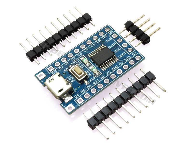
Sduino is still under development and does not currently support a good number of popular Arduino libraries, but it supports enough to be useful. So for today’s tutorial, I will examine the process involved in setting up your Arduino IDE to program an STM8 based microcontroller. For demonstration purposes, we will use the STM8S103F Development Board, and our goal will be to upload the blink example to the board.
Ready? let’s go
Required Components
The following components are required to follow this tutorial:
- The STM8S103F Development Board
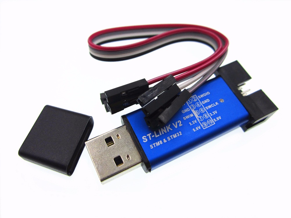
- The ST link V2 programmer
- A breadboard
- Jumper wires
All of these components can be bought from your favorite electronics component store. We will use the LED onboard the STM8S103F development board, but if you will like to use a normal LED, you can add a LED and a 220 ohms current limiting resistor to the list of components.
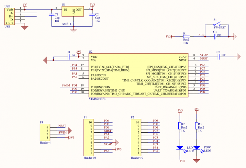
Schematics
Since we will implement the blink example using the LED onboard the STM8S103F, there is not much to do in terms of schematics. However, for those who may not be familiar with the process of connecting the ST link programmer to the STM8S103F board, the connection is described in the schematics below:
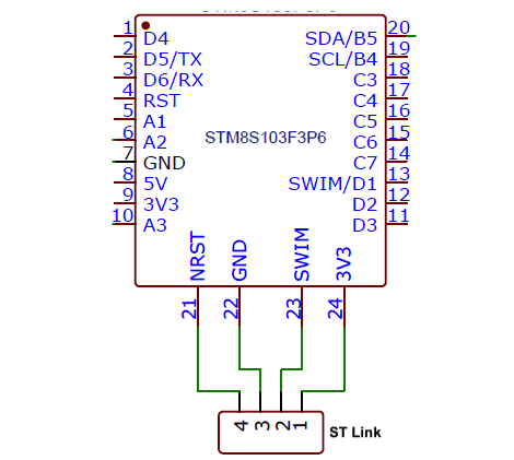
For clarity, a pin map showing how the components are connected is provided below;
ST-Link V2 –STM8S103F3
1(3.3v) - 3v3
2(SWIM) - SWIM
3(GND) - GND
4(RST) - NRST
Go over the connections again to ensure everything is as it should be. If you are using the ST-Link for the first time, you will be required to install the driver and set things up. In most situations, driver installations will start automatically immediately you connect the ST-Link programmer to your computer.
Arduino IDE Setup
To make the process of integrating open-source boards with the Arduino IDE easier, the IDE comes with a feature called “board manager“. Through the board manager, new boards (essentially software-based components required for the Arduino IDE to be able to upload code to a particular MCU) can be added to the IDE. These software-based components, often called cores, are usually developed by manufacturers of the board (like Sparkfun does for its boards) or a group of users with the desire to see their board work with the Arduino IDE. The Sduino represents the core for the STM8s boards and we will be installing it on the Arduino IDE using the board manager. Follow the steps below to do this:
1. Open the preferences window from the Arduino IDE. Go to File > Preferences
2. On the preferences window, locate the “Additional Board Manager URLs” text box and enter this link; https://github.com/tenbaht/sduino/raw/master/package_sduino_stm8_index.json into the field as shown below. As you may have other URLs there already, separate the URLs from each other using a comma (“,”) and click OK when done.
3. Next, open the Arduino board manager. Go to tools>Boards>Boards manager
4. When the board manager opens up, enter Sduino into the search bar. You should see the Sduino core come up as shown in the image below. Click on the install button to install the core.
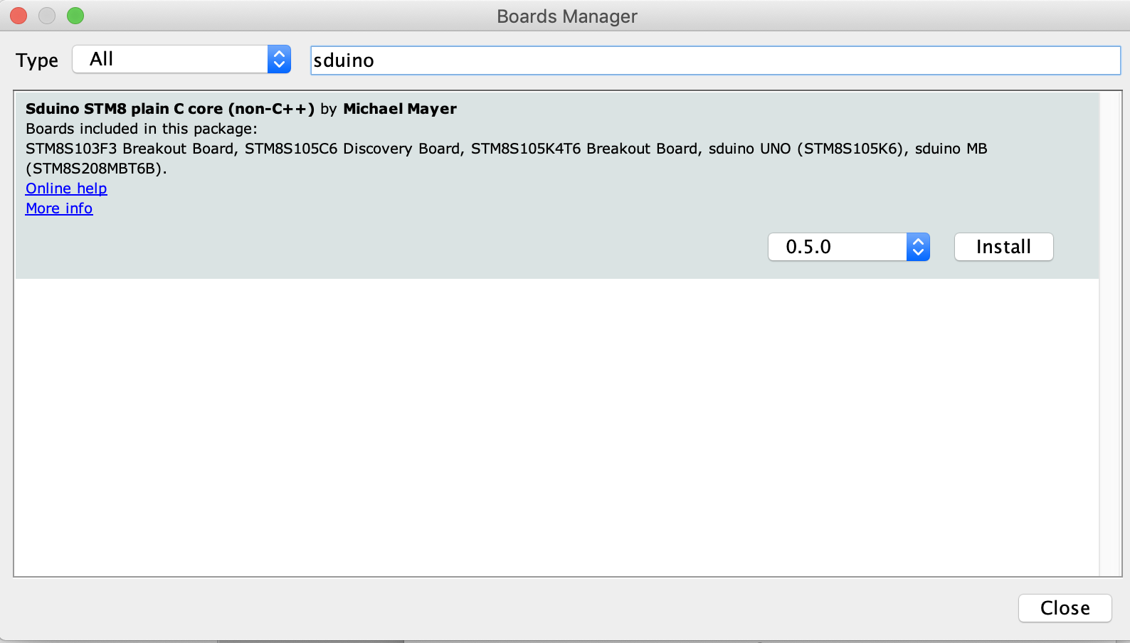
5. With the installation complete, close the board manager. The STM8s boards should now be available under the list of boards as shown in the image below.
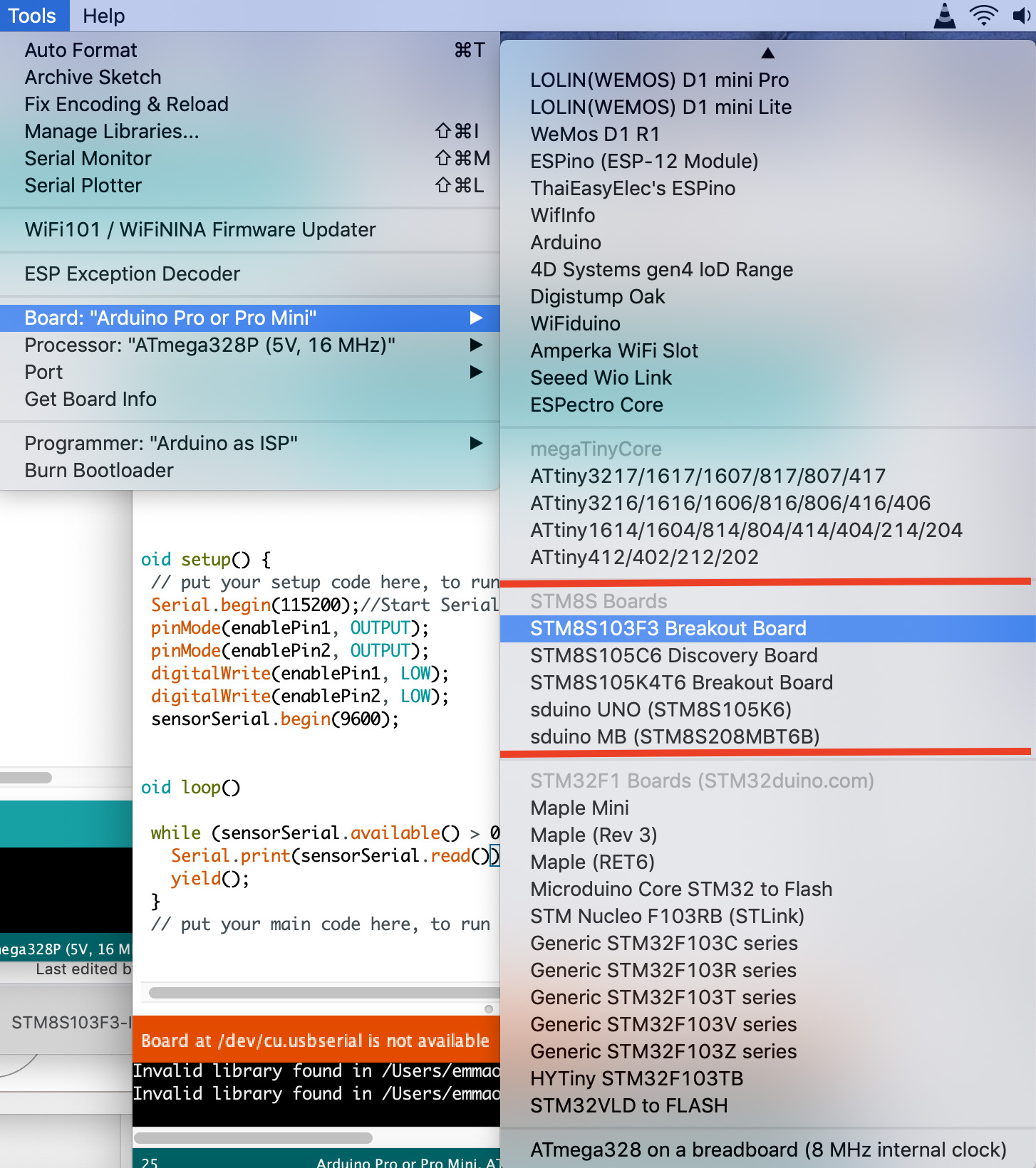
6. Installing the Sduino core will automatically install some Arduino libraries that have been modified to work with STM8s boards. Set your board type (by going to tools -> boards) to one of the STM8s boards, and go to examples (File -> examples). You will see a list of examples for the newly installed libraries.
With this done, you now have all you need to upload code to the STM8s boards.
Code
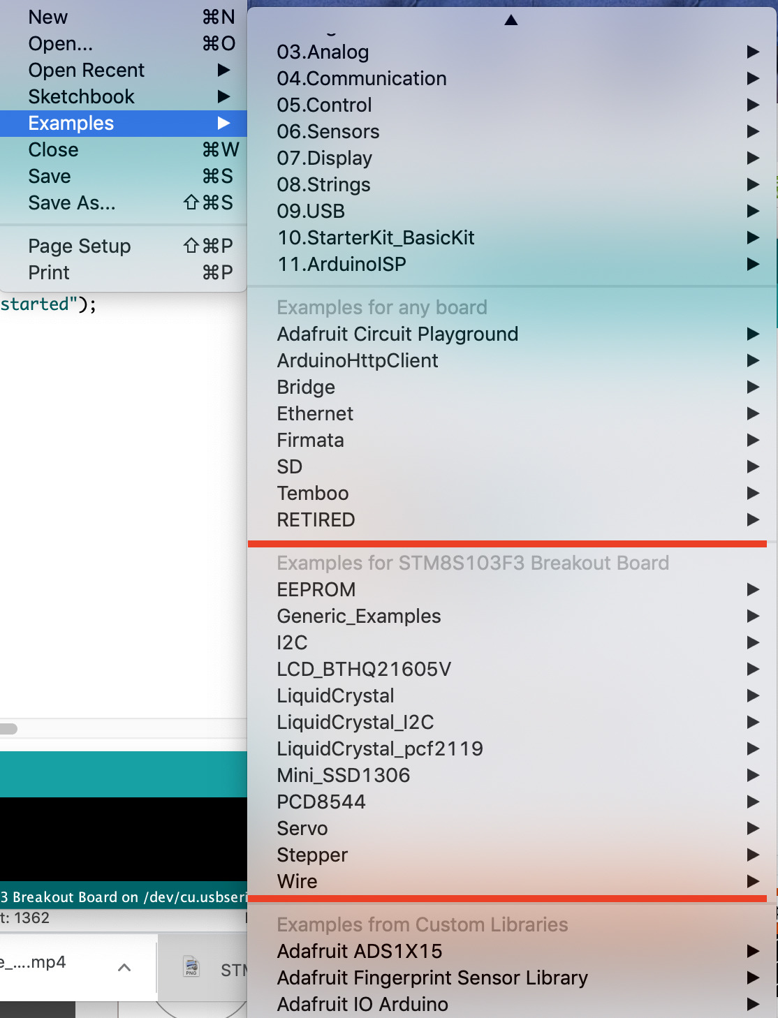
As mentioned during the introduction, for demonstration purposes, we will upload the blink example to the STM8S103F Development Board. You can use the generic blink example (File -> Example -> Basics -> Blink) or use the blink example among the STM8s Specific libraries (File -> Example -> Generic_Example -> Basics -> Blink).
I believe the code for the blink example needs no explanation and if you compare the two sketches you will see that they are exactly the same.
void setup() {
  // initialize digital pin LED_BUILTIN as an output.
  pinMode(LED_BUILTIN, OUTPUT);
}
// the loop function runs over and over again forever
void loop() {
  digitalWrite(LED_BUILTIN, HIGH);   // turn the LED on (HIGH is the voltage level)
  delay(1000);                       // wait for a second
  digitalWrite(LED_BUILTIN, LOW);    // turn the LED off by making the voltage LOW
  delay(1000);                       // wait for a second
}
Code Upload
Ensure your board is connected to the computer via the ST-link as described in the schematics. On the Arduino IDE, ensure the right board type is selected, and for set the programmer to ST-Link/V2 as shown in the image below:
With this done, hit the upload button, you should see the onboard LED begin to blink.
That’s it!
The Arduino IDE and Sduino provides a pathway to help you jumpstart development with STM8S. However, the platform is still under development and many Arduino libraries are yet to be supported.
That’s it for this tutorial! feel free to reach out to me via the comment section with questions or any clarifications you require.
Introduction: STM8s Breakout Board/ ST-Link V2 Connection Failure in Arduino Environment
A 16Mhz, 8bit microcontroller with 16 GPI’s and 5 AD 10 bits converter by ~1.5USD sure catch my attention. Its cost is less then a naked ATM328 chip.
But I find get it connect to Arduino IDE environment has its own trick.
Lt’s take a look in STM8S103F3P prototype module and understand why some of then get problems upload sketch.
Supplies
— STM8S103P3 module (https://www.aliexpress.com/item/1005001906773540.h…
-ST-Link V2 Debug Tool (https://www.aliexpress.com/item/32887775852.html?s…
-Arduino IDE
-ST Visual Programmer * (https://my.st.com/content/my_st_com/en/products/de…
* needs site login
Step 1: Preparing Computer Host
I will not get in to Arduino IDE installation details. There are a full hand of sites out there explain it. But after install it, It would be necessary get libs to work with STM8S.
- Install Arduino IDE
- Select File > Preferences and at «Additional Boards URLs:», add:
- https://github.com/tenbaht/sduino/raw/master/package_sduino_stm8_index.json
Note: If you already have other URL, click in little «window» icon next text box. It will open a multi-line text box window. EACH line is a URL. just add above link as new line in it.
- Go Tools Menu > Boards and select «Boards Manager». It will open a Window of Arduino IDE available boards library. In text box type STM8.
- «Sduino STM8 Plain C core (non C++)» option will appear. Click «Install». Close window after install.
- Go back to «Tools» Menu >»Boards Manager» and looking for «STM8S103F3 Breakout board». Ports will not matter, BUT you must go Tools > Programmer and select «ST-Link/V2».
Step 2: Hardware Description and Connection
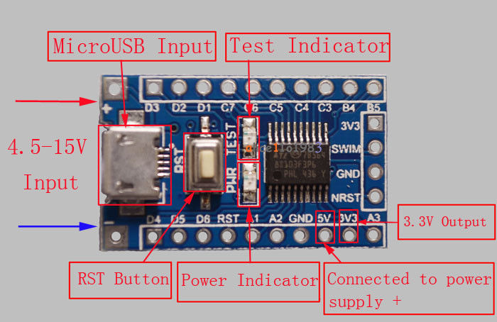
First things first: Despite AliExpress point USB connector as «input», it is just for power purpose. If you take a look in board diagram, notice only Vusb and GND are connect. So, how upload sketch to this fellow?
Basically, will be necessary ST-Link V2 connected to P3 4 pin header.
It is quite strait forward:
ST-Link V2 ———————————————STM8S modules P3
SWIM (5)————————————————P3 SWIM (2)
GND (3)—————————————————P3 GND (3)
RST (1)—————————————————P3 NRST (4)
I do not recommend power module via ST-Link. May work or may not, depend on Chinese manufacture you acquire it from.
Breakout Board has power LED indicator and LED for test purpose, connected to PB5, which correspond to Arduino D3 pin.
Pinout picture show AD inputs are shared to some of GPIO and perhaps has a special access code (like SRTM32 Blue pill).
Something is very important: Lib is plain C NOT C++ like regular Arduino libs. It will impact how write some instructions in sketch, but I will deal with it in future….
Step 3: Problems Loading Sketch
All sites described load first sketch as strait process, just select «Blink» example under File > Examples > Exemples for STM8S103F3… Generic_Examples > Basics > Blink and press and press «Upload» button….
Guess what? Did not work.
Arduino IDE raise «missing ‘program.params.quiet’ configuration parameter» error while upload.
I could not get any specific information about it, but I was pretty sure it was not tiny board problem, once it was originally «blinking» test LED in 1/2 Sec frequency, and after it I check cabling connection to be sure it was right, I start test ST-Link.
- Cross my mind use ST-Link Utility test ST-Link, but it returns a target (the board) connection error, so it was not conclusive.
- Then I remember ST-Link Menu > Firmware Update get connection only to ST-Link an can tell me ST-Link connection to computer was ok. So click in «Device Connect» will bring firmware version and device type. Close everything and go to next item.
If nothing pops up, you may have a bad ST-Link.
I double check cabling connection and now I am sure now it is something related to STM8S breakout board, but what? So, I found an article in internet, describing a similar problem and recommended use «ST Visual Programmer» to check STM8S memory and status.
- Running it, be sure to configure «Hardware» as ST-LINK, «Port» as USB, «Programming Mode» as SWIM and «Device» as STM8S103F3. This guy is able to reading what ever is inside STM8S memory and more important the option byte. In my case, any time I try read or write garbage to STM8S I get a access protection message….
- So, looking in «Option Byte» table I found «Read Out Protection was ON», so I change it to OFF, click in «Program Current Tab» and all good now.
NOTE: Looks Option Byte is same thing as fuses in ATM328, so take care change other itens..
Step 4: Conclusion
There is not much article out there about this board, so I hot it help one are starting working with it. This is just first step.
I hope issue more articles covering other experiences with this module.
Be the First to Share
Recommendations
Contents
-
ST STM8S103F3 Breakout Board
-
Hardware
-
Configuration
-
Uploading
-
Debugging
-
Frameworks
-
Hardware
Platform ST STM8: The STM8 is an 8-bit microcontroller family by STMicroelectronics an extended variant of the ST7 microcontroller architecture. STM8 microcontrollers are particularly low cost for a full-featured 8-bit microcontroller.
|
Microcontroller |
STM8S103F3P6 |
|
Frequency |
16MHz |
|
Flash |
8KB |
|
RAM |
1KB |
|
Vendor |
ST |
Configuration
Please use stm8sblue ID for board option in “platformio.ini” (Project Configuration File):
[env:stm8sblue]
platform = ststm8
board = stm8sblue
You can override default ST STM8S103F3 Breakout Board settings per build environment using
board_*** option, where *** is a JSON object path from
board manifest stm8sblue.json. For example,
board_build.mcu, board_build.f_cpu, etc.
[env:stm8sblue]
platform = ststm8
board = stm8sblue

; change microcontroller
board_build.mcu = stm8s103f3p6

; change MCU frequency
board_build.f_cpu = 16000000L
Uploading
ST STM8S103F3 Breakout Board supports the following uploading protocols:
-
serial -
stlinkv2
Default protocol is serial
You can change upload protocol using upload_protocol option:
[env:stm8sblue]
platform = ststm8
board = stm8sblue

upload_protocol = serial
Debugging
Debugging — “1-click” solution for debugging with a zero configuration.
Warning
You will need to install debug tool drivers depending on your system.
Please click on compatible debug tool below for the further
instructions and configuration information.
You can switch between debugging Tools & Debug Probes using
debug_tool option in “platformio.ini” (Project Configuration File).
ST STM8S103F3 Breakout Board does not have on-board debug probe and IS NOT READY for debugging. You will need to use/buy one of external probe listed below.
|
Compatible Tools |
On-board |
Default |
|---|---|---|
|
ST-LINK |
Yes |
Frameworks
|
Name |
Description |
|---|---|
|
Arduino |
Arduino Wiring-based Framework allows writing cross-platform software to control devices attached to a wide range of Arduino boards to create all kinds of creative coding, interactive objects, spaces or physical experiences |
|
Standard Peripheral Library |
The ST Standard Peripheral Library provides a set of functions for handling the peripherals on the STM32 family of microcontrollers. |
Generic STM8S103 breakout board
These simple breakout boards are available on aliexpress for well under one
Dollar (I got mine for 67 cent each, including shipping from China). These
boards are my main development platform.
Features
The hardware features are quite similar to an ATmega8:
| Boardname | stm8blue |
|---|---|
| CPU | STM8S103F3P6 |
| Clock | 16MHz, internal oscillator |
| Flash | 8kB |
| RAM | 1kB |
| EEPROM | 640 byte |
| I/O voltage | 3.3V |
| GPIO | 14 |
| serial connections | UART, SPI, I2C |
| PWM | 4 (up to 7 via alternate mapping) |
| ADC | 5 channel, 10 bit |
| LED | PB5 (Arduino D3), active low, shared with I2C, red |
| programming interface | SWIM, no serial bootloader |
| USB connector | mini, power only (data lines not connected) |
One (red) LED is connected to GPIO PB5 (CPU pin 11). This LED is low active.
Please keep in mind that this is one of the I2C signals and using the LED
blocks the I2C bus. The push button is for reset. The CPU runs on 3.3V, a
linear regulator is integrated on the board. The micro USB connector is only
for (5V) power supply, the data lines are not connected.
All CPU pins are easily accessible on (optional) pin headers (pitch 2.54mm,
perfect for breadboards).
They are very similar to the ESP14 Wifi-boards and
most programs will work fine on those chinese gems as well.
I am using the ST-Link V2 compatible flash tool in the green plastic
housing. The one in the metal housing uses a different pinout.
Connection to the flashtool:
| Signal name | P3 on CPU board | Green flash tool | Metal flash tool |
|---|---|---|---|
| 3V3 | 1 | 2 | 7 |
| SWIM | 2 | 5 | 5 |
| GND | 3 | 7 | 3 |
| NRST | 4 | 9 | 1 |
Crap alert
Due to bad PCB production quality, some more recent lots (as of 2020) of the
stm8blue boards seem to have either no working connection to GND on the SWIM
connector or a short circuit from the SWIM pin to GND.
 The SWIM pin is shortend to GND
Try connecting GND to the other GND board pin or power the board via USB.
Most boards ship with a pre-programmed blinky. If the LED blinks when the
board is powered via USB but doesn’t when it is only connected to the flash
tool, your board is probably missing the GND connection.
Unlocking a write protected MCU
My breakout boards came preprogrammed with a blink program and with active
write protection bits. For unlocking before first use using the command
line:
stm8flash -cstlinkv2 -pstm8s103?3 -u
The same can be done from the Arduino IDE by clicking on Tools->Burn
Bootloader after selecting an STM8 based board and choosing the correct
programmer type (ST-Link V2). The name of this menu entry is not
self-explanatory, but I couldn’t find any way to change it or to add another
entry with a better name. (If you know how, please open an issue)
The required binary for stm8flash is included in the download of the
automatic install. On Windows systems it can be found in the directory
AppDataLocalArduino15packagessduinotoolsSTM8Tools2019.02.05win.
A GUI alternative is the STVP tool by ST, but this involves installing
another software package (see
issue#85).
Pin number mappings
The Arduino environment uses its own pin numbering scheme independent from
the physical CPU pin numbers. Many Arduino sketches and libraries contain
hard-coded assumptions about the number of pins with special functions.
Ideally, all these numbers would be the same and all programs could be
compiled without changes.
Here I discuss some possible pin mapping
schemes and check how close we could get to the ideal mapping.
Unfortunatly, it turns out that a perfect mapping is not possible.
In the end I chose a simple geometric numbering for the square UFQFPN20
package starting with port pin PA1 and counting up from 0. This results in
this mapping:
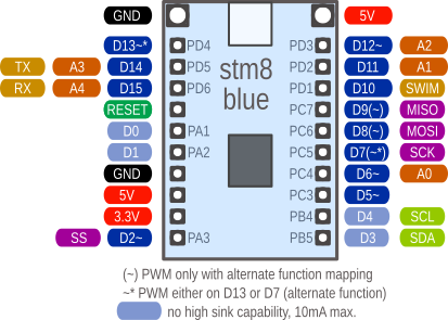
| sduino pin | STM8S103 CPU port pin |
|---|---|
| 0-2 | PA1-PA3 (PA1 and PA2 only weak output drivers) |
| 3-4 | PB5-PB4 (reverse order) |
| 5-9 | PC3-PC7 |
| 10-15 | PD1-PD6 |
- serial: 14,15
- SPI: 2,7,8,9
- I2C: 3,4 (true open drain. can’t drive a high signal without an external
pull-up resistor) - Analog: 6,11,12,14,15
- PWM: 2,5,6,12 plus either only 13 or 7-9 but not 13 (via alternate mapping)
pros of this approach:
- Easy and logical for use on a breadboard
- Very clear and logical port pin ordering
- TX and RX would be the rarely used analog pin numbers A3/A4 at
the end of the analog pin number list - At least the analog pins are in data sheet order
cons of this approach:
- Analog pins are still scattered around
- All functions use totally different pin numbers than Arduino
I am still not really happy with this mapping. Instead of simplifing things
it only adds another layer of abstraction and confusion. To avoid this I
added definitions for the regular CPU pin names like PA1 and PD2. In the
end, this notation seems to be a lot easier to me. I am open for suggestions
for a better pin number mapping.
The chosen pin mapping for the STM8S103 (possible alternate function in
paratheses):
| Phys. STM8 pin | Name | Functions | Geometrical mapping | special funcion |
|---|---|---|---|---|
| 1 | PD4 | UART_CLK/T2-1/beep | 13 | PWM |
| 2 | PD5 | TX/Ain5 | 14 | Analog A3 |
| 3 | PD6 | RX/Ain6 | 15 | Analog A4 |
| 5 | PA1 | (OscIn, no HS) | 0 | |
| 6 | PA2 | (OscIn, no HS) | 1 | |
| 10 | PA3 | SS/T2-3 | 2 | PWM |
| 11 | PB5 | SDA LED | 3 | |
| 12 | PB4 | SCL | 4 | |
| 13 | PC3 | T1-3/[T1-n1] | 5 | PWM, (n~) |
| 14 | PC4 | T1-4/Ain2/[T1-n2] | 6 | PWM, Analog A0, (n~) |
| 15 | PC5 | SCK/[T2-1] | 7 | (~) |
| 16 | PC6 | MOSI/[T1-1] | 8 | (~) |
| 17 | PC7 | MISO/[T1-2] | 9 | (~) |
| 18 | PD1 | (SWIM) | 10 | |
| 19 | PD2 | Ain3/[T2-3] | 11 | Analog A1, (~~) |
| 20 | PD3 | Ain4/T2-2 | 12 | PWM, Analog A2 |
Special pins
The pins D3/D4 (SDA/SCL, PB5/PB4) are different from the others as they are
true open drain pins. That means, they only can drive the output low or
open. To drive it high, they require an external pull-up resistor. This is
the reason why the LED on this breakout board is connected between +3.3V and
the pins and not between the pin and GND as usual. This way it is possible
to drive the LED by writing a zero to the output register.
D5/D6 (PA1/PA2, OscIn/OscOut) are weaker than the other pins. Try avoiding
these pins for LEDs and other higher current applications.
Schematic
Did a board manager install of Sduino per the instructions (running Arduino 1.8.19):
Start the Arduino-IDE. In File->Preferences, Settings tab, enter
https://github.com/tenbaht/sduino/raw/master/package_sduino_stm8_index.json
as an Additional Boards Manager URL.
Open Tools->Board:…->Boards Manager
Find Sduino by typing ‘sd’ into the search line
Click on the list entry
Click on Install.
blink LED program is working but some program gives error for example serial communication code and ultrasonic code
after that getting this error
«Error compiling for board STM8S103F3 Breakout Board».
complete error is below.
:UserstanveAppDataLocalArduino15packagessduinotoolssdccbuild.11242/bin/sdcc sketchHCSR04.ino.cpp preprocctags_target_for_gcc_minus_e.cpp re12 -c -Ddouble=float -DUSE_STDINT -D__PROG_TYPES_COMPAT__ -E -MC -mstm8 -DSTM8S103 -DF_CPU=16000000L -DARDUINO=10819 -DARDUINO_STM8S_BLUE -DARDUINO_ARCH_STM8 -IC:UserstanveAppDataLocalArduino15packagessduinohardwarestm8.5.0coressduino -IC:UserstanveAppDataLocalArduino15packagessduinohardwarestm8.5.0variantsstandard -IC:UserstanveDocumentsArduinolibrariesHCSR04_ultrasonic_sensorsrc -IC:UserstanveAppDataLocalArduino15packagessduinohardwarestm8.5.0/STM8S_StdPeriph_Driver/inc -IC:UserstanveAppDataLocalArduino15packagessduinotoolssdccbuild.11242/include
Mark re12:C:UserstanveAppDataLocalArduino15packagessduinotoolssdccbuild.11242/bin/sdcc -c -Ddouble=float -DUSE_STDINT -D__PROG_TYPES_COMPAT__ -E -MC -mstm8 -DSTM8S103 -DF_CPU=16000000L -DARDUINO=10819 -DARDUINO_STM8S_BLUE -DARDUINO_ARCH_STM8 -IC:UserstanveAppDataLocalArduino15packagessduinohardwarestm8.5.0coressduino -IC:UserstanveAppDataLocalArduino15packagessduinohardwarestm8.5.0variantsstandard -IC:UserstanveDocumentsArduinolibrariesHCSR04_ultrasonic_sensorsrc -IC:UserstanveAppDataLocalArduino15packagessduinohardwarestm8.5.0/STM8S_StdPeriph_Driver/inc -IC:UserstanveAppDataLocalArduino15packagessduinotoolssdccbuild.11242/include sketchHCSR04.ino.cpp -o preprocctags_target_for_gcc_minus_e.cpp
cpp gefunden
C:UserstanveAppDataLocalArduino15packagessduinotoolssdccbuild.11242/bin/sdcc sketchHCSR04.ino.cpp sketchHCSR04.ino.cpp.o re2 -MMD -c -Ddouble=float -DUSE_STDINT -D__PROG_TYPES_COMPAT__ —less-pedantic -mstm8 -DSTM8S103 -DF_CPU=16000000L -DARDUINO=10819 -DARDUINO_STM8S_BLUE -DARDUINO_ARCH_STM8 -IC:UserstanveAppDataLocalArduino15packagessduinohardwarestm8.5.0coressduino -IC:UserstanveAppDataLocalArduino15packagessduinohardwarestm8.5.0variantsstandard -IC:UserstanveDocumentsArduinolibrariesHCSR04_ultrasonic_sensorsrc -IC:UserstanveAppDataLocalArduino15packagessduinohardwarestm8.5.0/STM8S_StdPeriph_Driver/inc -IC:UserstanveAppDataLocalArduino15packagessduinotoolssdccbuild.11242/include
Mark re2:C:UserstanveAppDataLocalArduino15packagessduinotoolssdccbuild.11242/bin/sdcc -MMD -c -Ddouble=float -DUSE_STDINT -D__PROG_TYPES_COMPAT__ —less-pedantic -mstm8 -DSTM8S103 -DF_CPU=16000000L -DARDUINO=10819 -DARDUINO_STM8S_BLUE -DARDUINO_ARCH_STM8 -IC:UserstanveAppDataLocalArduino15packagessduinohardwarestm8.5.0coressduino -IC:UserstanveAppDataLocalArduino15packagessduinohardwarestm8.5.0variantsstandard -IC:UserstanveDocumentsArduinolibrariesHCSR04_ultrasonic_sensorsrc -IC:UserstanveAppDataLocalArduino15packagessduinohardwarestm8.5.0/STM8S_StdPeriph_Driver/inc -IC:UserstanveAppDataLocalArduino15packagessduinotoolssdccbuild.11242/include sketchHCSR04.ino.cpp -o sketchHCSR04.ino.cpp.o
cpp gefunden
C:/Users/tanve/Documents/Arduino/libraries/HCSR04_ultrasonic_sensor/src/HCSR04.h:4: syntax error: token -> ‘HCSR04’ ; column 12
exit status 1
Error compiling for board STM8S103F3 Breakout Board.
It said it has mutiple libraries were found for «nRF24L01.h»
but i check the Ardurino libraries I can only found one.
And it work fine if I compile it to Arduino uno.
//Include Libraries
#include <SPI.h>
#include <nRF24L01.h>
#include <RF24.h>

//create an RF24 object
RF24 radio(8,9 );  // CE, CSN

//address through which two modules communicate.
const byte address[6] = "00001";

void setup() {
  // put your setup code here, to run once:

  while (!Serial);
    Serial.begin(9600);

  radio.begin();

  //set the address
  radio.openReadingPipe(0, address);

  //Set module as receiver
  radio.startListening();
}

void loop() {
  // put your main code here, to run repeatedly:

  if (radio.available())
  {
    char text[32] = {0};
    radio.read(&text, sizeof(text));

    Serial.println(text);


  }

}
Here is the error message
Arduino: 1.8.10 (Windows 8.1), Board: "STM8S103F3 Breakout Board"

Multiple libraries were found for "nRF24L01.h"
bash.exe: warning: could not find /tmp, please create!
 Used:
C:UsersUserNameDocumentsArduinolibrariesRF24
C:UsersUserNameAppDataLocalArduino15packagessduinotoolssdccbuild.10738/bin/sdcc sketchreceiver.ino.cpp

nul re12 -c -Ddouble=float -DUSE_STDINT -D__PROG_TYPES_COMPAT__ -E -MC -mstm8 -DSTM8S103 -DF_CPU=16000000L
-DARDUINO=10810 -DARDUINO_STM8S_BLUE -DARDUINO_ARCH_STM8
-IC:UsersUserNameAppDataLocalArduino15packagessduinohardwarestm8.4.0coressduino
-IC:UsersUserNameAppDataLocalArduino15packagessduinohardwarestm8.4.0variantsstandard
-IC:UsersUserNameDocumentsArduinolibrariesRF24
-IC:UsersUserNameAppDataLocalArduino15packagessduinohardwarestm8.4.0/STM8S_StdPeriph_Driver/inc
-IC:UsersUserNameAppDataLocalArduino15packagessduinotoolssdccbuild.10738/include
Mark re12:C:UsersUserNameAppDataLocalArduino15packagessduinotoolssdccbuild.10738/bin/sdcc -c -Ddouble=float -DUSE_STDINT -D__PROG_TYPES_COMPAT__ -E -MC -mstm8 -DSTM8S103 -DF_CPU=16000000L -DARDUINO=10810 -DARDUINO_STM8S_BLUE -DARDUINO_ARCH_STM8 -IC:UsersUserNameAppDataLocalArduino15packagessduinohardwarestm8.4.0coressduino -IC:UsersUserNameAppDataLocalArduino15packagessduinohardwarestm8.4.0variantsstandard -IC:UsersUserNameDocumentsArduinolibrariesRF24 -IC:UsersUserNameAppDataLocalArduino15packagessduinohardwarestm8.4.0/STM8S_StdPeriph_Driver/inc -IC:UsersUserNameAppDataLocalArduino15packagessduinotoolssdccbuild.10738/include sketchreceiver.ino.cpp -o nul
cpp gefunden
In file included from C:/Users/UserName/Documents/Arduino/libraries/RF24/RF24.h:18,
                 from C:UsersUserNameDesktopmadreceiverreceiver.ino:4:

C:/Users/UserName/Documents/Arduino/libraries/RF24/RF24_config.h:143:30:
fatal error: avr/pgmspace.h: No such file or directory

compilation terminated.

exit status 1
Error compiling for board STM8S103F3 Breakout Board.

This report would have more information with
"Show verbose output during compilation"
option enabled in File -> Preferences.
Страница 3 из 3
-
Аналагиична.Не впечатлило.Ничем.
-
Это все фигня. Вот когда вы научитесь считать, сколько стоит время, потраченное на освоение нового контроллера, вы поймете, что по сравнению с ним цена самого чипа пренебрежимо мала, и что между чипом за 10р и за 1000р в этом смысле практически нет разницы. Цена штуки играет только в большой серии. У нового чипа должно быть какое-то неоспоримое техническое преимущество, которое бы обосновывало его применение.
-
Не будет никакого технического преимущества между МК за 2 зеленых рубля и МК за 2 зеленых рубля. Будет другая периферия, другой набор возможностей, но вычислительная способность будет той же.
-
Есть интересные проекты на примете?
У меня валяются разные MSP-шки случайные из разных серий, было бы любопытно их приткнуть куда-нибудь с пользой… -
Есть две оттрасированные платы. Скоро нарисую ещё одну и зашлю китайцам. Но у меня сейчас на халтуре другие проекты, поэтому на электронику времени мало остаётся.
Последнее редактирование: 10 дек 2019
-
Чеза халтура?Мешки ворочаешь?
Последнее редактирование: 10 дек 2019
-
подскажите как залить скеч в стм8 в IDE через нано
я беру +5в и минус с неё и соответственно на стм8
а рх на рд6 а тх на рд5но при заливке выскакивает ошибка
Arduino: 1.8.11 (Windows 10), Плата:«STM8S103F3 Breakout Board»d:dokumentPortableFLProg_6—3—1_Win64ideV5portablepackagessduinotoolssdccbuild.11242/bin/sdcc sketchBlink.ino.cpp preprocctags_target_for_gcc_minus_e.cpp re12 —c —Ddouble=float —DUSE_STDINT —D__PROG_TYPES_COMPAT__ —E —MC —mstm8 —DSTM8S103 —DF_CPU=16000000L —DARDUINO=10811 —DARDUINO_STM8S_BLUE —DARDUINO_ARCH_STM8 —ID:dokumentPortableFLProg_6—3—1_Win64ideV5portablepackagessduinohardwarestm8.5.0coressduino —ID:dokumentPortableFLProg_6—3—1_Win64ideV5portablepackagessduinohardwarestm8.5.0variantsstandard —ID:dokumentPortableFLProg_6—3—1_Win64ideV5portablepackagessduinohardwarestm8.5.0/STM8S_StdPeriph_Driver/inc —Id:dokumentPortableFLProg_6—3—1_Win64ideV5portablepackagessduinotoolssdccbuild.11242/include
Mark re12:d:dokumentPortableFLProg_6—3—1_Win64ideV5portablepackagessduinotoolssdccbuild.11242/bin/sdcc —c —Ddouble=float —DUSE_STDINT —D__PROG_TYPES_COMPAT__ —E —MC —mstm8 —DSTM8S103 —DF_CPU=16000000L —DARDUINO=10811 —DARDUINO_STM8S_BLUE —DARDUINO_ARCH_STM8 —ID:dokumentPortableFLProg_6—3—1_Win64ideV5portablepackagessduinohardwarestm8.5.0coressduino —ID:dokumentPortableFLProg_6—3—1_Win64ideV5portablepackagessduinohardwarestm8.5.0variantsstandard —ID:dokumentPortableFLProg_6—3—1_Win64ideV5portablepackagessduinohardwarestm8.5.0/STM8S_StdPeriph_Driver/inc —Id:dokumentPortableFLProg_6—3—1_Win64ideV5portablepackagessduinotoolssdccbuild.11242/include sketchBlink.ino.cpp —o preprocctags_target_for_gcc_minus_e.cpp
cpp gefunden
d:dokumentPortableFLProg_6—3—1_Win64ideV5portablepackagessduinotoolssdccbuild.11242/bin/sdcc sketchBlink.ino.cpp sketchBlink.ino.cpp.o re2 —MMD —c —Ddouble=float —DUSE_STDINT —D__PROG_TYPES_COMPAT__ —less—pedantic —mstm8 —DSTM8S103 —DF_CPU=16000000L —DARDUINO=10811 —DARDUINO_STM8S_BLUE —DARDUINO_ARCH_STM8 —ID:dokumentPortableFLProg_6—3—1_Win64ideV5portablepackagessduinohardwarestm8.5.0coressduino —ID:dokumentPortableFLProg_6—3—1_Win64ideV5portablepackagessduinohardwarestm8.5.0variantsstandard —ID:dokumentPortableFLProg_6—3—1_Win64ideV5portablepackagessduinohardwarestm8.5.0/STM8S_StdPeriph_Driver/inc —Id:dokumentPortableFLProg_6—3—1_Win64ideV5portablepackagessduinotoolssdccbuild.11242/include
Mark re2:d:dokumentPortableFLProg_6—3—1_Win64ideV5portablepackagessduinotoolssdccbuild.11242/bin/sdcc —MMD —c —Ddouble=float —DUSE_STDINT —D__PROG_TYPES_COMPAT__ —less—pedantic —mstm8 —DSTM8S103 —DF_CPU=16000000L —DARDUINO=10811 —DARDUINO_STM8S_BLUE —DARDUINO_ARCH_STM8 —ID:dokumentPortableFLProg_6—3—1_Win64ideV5portablepackagessduinohardwarestm8.5.0coressduino —ID:dokumentPortableFLProg_6—3—1_Win64ideV5portablepackagessduinohardwarestm8.5.0variantsstandard —ID:dokumentPortableFLProg_6—3—1_Win64ideV5portablepackagessduinohardwarestm8.5.0/STM8S_StdPeriph_Driver/inc —Id:dokumentPortableFLProg_6—3—1_Win64ideV5portablepackagessduinotoolssdccbuild.11242/include sketchBlink.ino.cpp —o sketchBlink.ino.cpp.o
cpp gefunden
Скетч использует 1703 байт (20%) памяти устройства. Всего доступно 8192 байт.
Глобальные переменные используют 72 байт (7%) динамической памяти, оставляя 952 байт для локальных переменных. Максимум: 1024 байт.
Determine FLASH areaCould not open USB device.
Произошла ошибка при загрузке скетчаЭтот отчёт будет иметь больше информации с
включенной опцией Файл —> Настройки —>
«Показать подробный вывод во время компиляции» -
а загрузчик в СТМ8 установлен?
куда катится мир… СТМ8 уже в ФЛПроге программируют
Блинк — 1700 байт -
так а как его устанавливать ?
я нашол сылку для иде через которую я скачал библиотеку на стм8
далее она определилась у меня в иде и я пробовал залить в неё блинк для начала но она не хочет -
а вот то, что надо подключаться к рд6 рд5 — это вы откуда взяли?
и что такое «рд5» вообще?
Что за плата СТМ8 у вас? -
я ознакомился с распиновкой платы и подключил к ней согласно её пинов
STM8S103F3P6 -
блин, это вы называете «эр-дэ-пять»?
Вообще-то это латиница По подключению — вы подключаетесь к RX TX СТМ8. С чего вы взяли, что СТМ8 можно так прошивать?
Вообще-то для прошивки СТМ8 используется SWIM интерфейс — видите с торца на плате есть 4 пина:
И для прошивки нужен программатор St-LINK
-
видел как на ютубе прошивали таким способом стм32
проблема что у меня нету програматора такого
но видимо прийдётся заказывать и его раз никак по другому -
ну так то стм32 — а у вас стм8. Это совсем не одно и тоже.. В СТМ32 изначально есть загрузчик, в СТМ8 ничего нет.
Поэтому, если вы хотите прошивать СТМ8 через RX TX — в плату сначала надо прошить загрузчик, а чтобы это сделать — все равно нужен программатор.
Так что круг замкнулся… имея программатор, нет никакого смысла заливаться через RX TX — через ст-линк удобнее.Последнее редактирование: 16 окт 2020
-
спасибо
теперь мне всё понятно
Страница 3 из 3
Loading